

Page 1

VIP-176A SIP Door Intercom
INTRODUCTION
The VIP-176A SIP Talkback Door Intercom
allows communication to SIP-based telephone
systems or Valcom Enhanced Station Port
adapters via an IP-based network.
SPECIFICATIONS
Access Methods
SIP – enabled telephone system
PBX, FXO Port w/Valcom Enhanced Station
Port
POTS telephone set w/Valcom Enhanced
Station Port
Valcom M Cast Page Group
Features
RJ-45 for network connection
1 Form C Smart Relay (optional)
Network activity LEDs
Power over Ethernet (PoE) 802.3af
compatible
Dimensions/Weight:
4.88” H x 4.88" W x 2.5" D (including button)
(12.4cm H x 12.4cm W x 6.4cm D)
Weight: 0.82 lbs. (0.37 kg)
Nominal Power Requirements
Via 802.3af PoE Ethernet Switch: Class 3
Environment
Network Interface:
Temperature: 0 to +40° C
Humidity: 0 to 85% non-precipitating
Suitable for indoor or outdoor installation,
protected from direct precipitation.
Precautionary Designations
FCC Information
This equipment has been tested and found to
comply with the limits for a Class A digital
device, pursuant to Part 15 of the FCC Rules.
These limits are designed to provide
reasonable protection against harmful
interference when the equipment is operated
in a commercial environment. This
equipment generates uses and can radiate
radio frequency energy and if not installed
and used in accordance with the instruction
manual, may cause harmful interference to
radio communications. Operation of this
equipment in a residential area may cause
harmful interference in which case the user
will be required to correct the interference at
his own expense.
CAUTION
RISK OF ELECTRIC SHOCK
DO NOT OPEN
CAUTION: To reduce the risk of electric shock,
Refer servicing to qualified service personnel.
Do not remove cover.
No user serviceable parts inside.
This symbol indicates that dangerous
voltage constituting a risk of electric
shock is present within this unit.
This symbol indicates that there are
important operating and maintenance
instructions in the literature accompanying
this unit.
ISSUE 1
1 947550
Page 2
INSTALLATION
Operation:
The VIP-176A provides door intercom access via
network connection to customer telephone
system or stand-alone telephone set. Interface to
customer telephone system can be via SIP
registration to a voice over IP (VoIP) telephone
system, or FXO port (when used with a Valcom
Enhanced Station Port). Pressing the call button
on the door plate initiates a call to a userspecified telephone number and the call
assurance LED on the door plate begins to flash.
When the call is answered, a hands-free
communications path is established to the door
plate, and the call assurance LED on the door
plate remains lit. An optional Smart Relay
module, VM-SRLY is available separately, which
provides one form C relay for uses such as
activating door entry equipment.
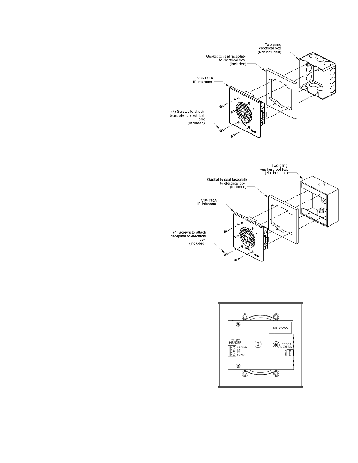
Mounting
For enhanced protection against static
electrical discharge, it is recommended the
VIP-176A be installed into a grounded
electrical box.
The VIP-176A Doorplate is designed for double
gang FD electrical box mounting. Verify depth of
electrical box is adequate for mounting the VIP176A. (See Figure 1)
When purchasing weatherproof box, the ground
screw should be off-center. For example, Bell
part number 5333-0 could be used.
(See Figure 2)
Power Connections
The only method of powering the VIP-176A is via
a Power over Ethernet (PoE) switch or power
injector meeting the 802.3af specification.
Make all required signal connections before
connecting to Ethernet switch or power injector
meeting the 802.3af specification.
Network Connection
The VIP-176A has one RJ-45 Network connector.
Green LED: (Link) Indicates Ethernet connection
when illuminated.
Yellow LED: (Activity) Indicator flashes to
indicate network activity.
Use a standard Ethernet patch cable to connect
the NETWORK connector to an Ethernet switch.
(See Figure 3).
Figure 1.
Figure 2.
Figure 3.
2 947550
Page 3

Status Indicator Lights
The VIP-176A Door plate is equipped with a
status indicator
LED. LED flashes when the call
button is pressed and steady when the call is
connected.
Relay Connections
An optional Smart Relay module, VM-SRLY, may
be ordered separately. Installation instructions to
connect with the VIP-176A Relay Header are
included with the VM-SRLY.
SETUP
Information specific to your application will need
to be programmed into the VIP-176A using a
computer. The PC used for programming should
be connected to the same subnet as the
VIP-176A. Setup will be done using the IP
Solution Setup Tool. Download the latest version
of the free IP Solutions Setup Tool from the
Valcom web site at
www.valcom.com/vipsetuptool
TECHNICAL ASSISTANCE
Assistance in troubleshooting is available from
the factory. Call (540) 563-2000 and press 1 for
Technical Support or via email at
support@valcom.com.
When requesting assistance, you should include
all available information. General information and
troubleshooting procedures are available on the
Valcom website at www.valcom.com.Valcom
equipment is not field repairable. Valcom, Inc.
maintains service facilities in Roanoke, VA.
Should repairs be necessary, attach a tag to the
unit clearly stating your company name, address,
phone number, contact person and the nature of
the problem.
Send the unit to:
Valcom, Inc.
Repair & Return Dept.
5614 Hollins Road
Roanoke, Va. 24019-5056
WARRANTY
Warranty information may be found on our
website at www.valcom.com/warranty
3 947550
 Loading...