

Page 1
ISSUE 3
VIP-130AL-IC InformaCast® Compliant
IP Paging Horn
INTRODUCTION
The VIP-130AL consists of a high efficiency horn
and a Network Interface compatible with
Singlewire InformaCast broadcasts.
The VIP-130AL is available in three colors,
Beige (-BGE), Gray (-GY) and Marine White
(-W).
The Marine version features additional weather
protection, including an O-ring seal on the bell
housing and stainless steel hardware.
IMPORTANT SAFETY INFORMATION
CONSIGNES DE SÉCURITÉ IMPORTANTES
1. Read these instructions.
Lisez ces instructions.
2. Keep these instructions.
Conservez ces instructions.
3. Heed all warnings.
Respectez tous les avertissements.
4. Follow all instructions.
Suivez toutes les instructions.
5. Do not use this apparatus near water.
Ne pas utiliser cet appareil près de l'eau.
6. Clean only with dry cloth.
Nettoyer avec un chiffon sec.
7. Do not block any ventilation openings. Install in accordance with the manufacturer’s
instructions.
Ne pas bloquer les ouvertures de ventilation. Installer formément aux instructions du
fabricant.
8. Do not install near any heat sources such as radiators, heat registers, stoves or other
apparatus (including amplifiers) that produce heat.
Ne pas installer à proximité de sources de chaleur telles que radiateurs, registres de
chaleur, poêles ou autres appareils (y compris les amplificateurs) produisant de la chaleur.
9. Do not defeat the safety purpose of the polarized or grounding-type plug. A polarized plug
has two blades with one wider than the other. A grounding type plug has two blades and a
third grounding prong. The wide blade and the third prong are provided for your safety. If
the provided plug does not fit into your outlet consult an electrician for replacement of the
obsolete outlet.
Ne pas contourner le dispositif de sécurité de la fiche polarisée ou de mise à la terre. Une
fiche polarisée possède deux lames dont une plus large que l'autre. Une fiche de terre a
deux lames et une troisième broche de mise à la terre. La lame large et la troisième
broche sont fournies pour votre sécurité. Si la fiche fournie ne rentre pas dans votre prise,
veuillez consulter un électricien pour le remplacement de la prise obsolète.
10.Protect the power cord from being walked on or pinched particularly at plugs, convenience
receptacles and the point where they exit from the apparatus.
11.Only use attachments/accessories specified by the manufacturer.
N'utilisez que des fixations / accessoires spécifiés par le fabricant.
12. Use only with the cart, stand, tripod, bracket or table specified
by the manufacturer or sold with the apparatus. When a cart is
used, use caution when moving the cart/apparatus combination
to avoid injury from tip-over.
Utilisez uniquement avec le chariot, stand, trépied, support ou table spécifié par le
fabricant ou vendu avec l'appareil. Quand un chariot est utilisé, Soyez prudent lorsque
vous déplacez l'ensemble chariot / appareil pour éviter des blessures dues au
renversement.
13. Unplug this apparatus during lightning storms or when unused for a long period of time.
Débranchez cet appareil pendant les orages ou lorsqu'il n'est pas utilisé pendant une
longue période de temps.
14. Refer all servicing to qualified service personnel. Servicing is required when the
apparatus has been damaged in any way. Such as when the power supply cord or plug is
damaged, liquid has been spilled, objects have fallen into the apparatus or the
apparatus has been exposed to rain or moisture and does not operate normally or has
been dropped.
Confiez toute réparation à un personnel qualifié. Une réparation est nécessaire lorsque
l'appareil a été endommagé de quelque façon. Par exemple lorsque le cordon
d'alimentation ou la fiche est endommagé, du liquide a été renversé, si des objets sont
tombés dans l'appareil ou le appareil a été exposé à la pluie ou à l'humidité et ne
fonctionne pas normalement ou s'il est tombé.
Installation
Mounting (Network Interface)
The Network Interface is designed for wall or
shelf mounting and must be within 300 feet of
the network switch.
Shelf: Provided with the Network Interface are
four rubber pads. Peel the pads from the carrier
backing and place at the four corners of the
bottom of the unit.
Wall: Using the brackets and wood screws
provided, secure the Network Interface to the
wall.
Mounting (Horn)
The VIP-130AL-IC Horn is designed for most FD
electrical box or wall mounting and must be
within 350 feet of the VIP-130AL Network
Interface. See NEMA OS 3-2002 sec.1.2.3.5 for
FD box specifications.
Attaching Speaker to Base
NOTE: For ease of installation, the base can be
attached to the speaker before or after the base
is mounted.
Loosen position adjustment knob
Insert the ball of the base into the socket of
the speaker
Tighten the position adjustment knob
These horns should be mounted 15 to 20 feet
above the floor to allow for best sound
distribution. The units can be mounted to a wall,
a beam or an electrical box.
A “C” clamp is provided with the horns to
allow mounting to a beam. When using the
“C” clamp for mounting, remove the signal
cable from the ball mount. Reinstall an
RJ45 connector on the signal cable after
mounting, using the T568B pinout scheme.
See Figure 1.
1 947819
Page 2
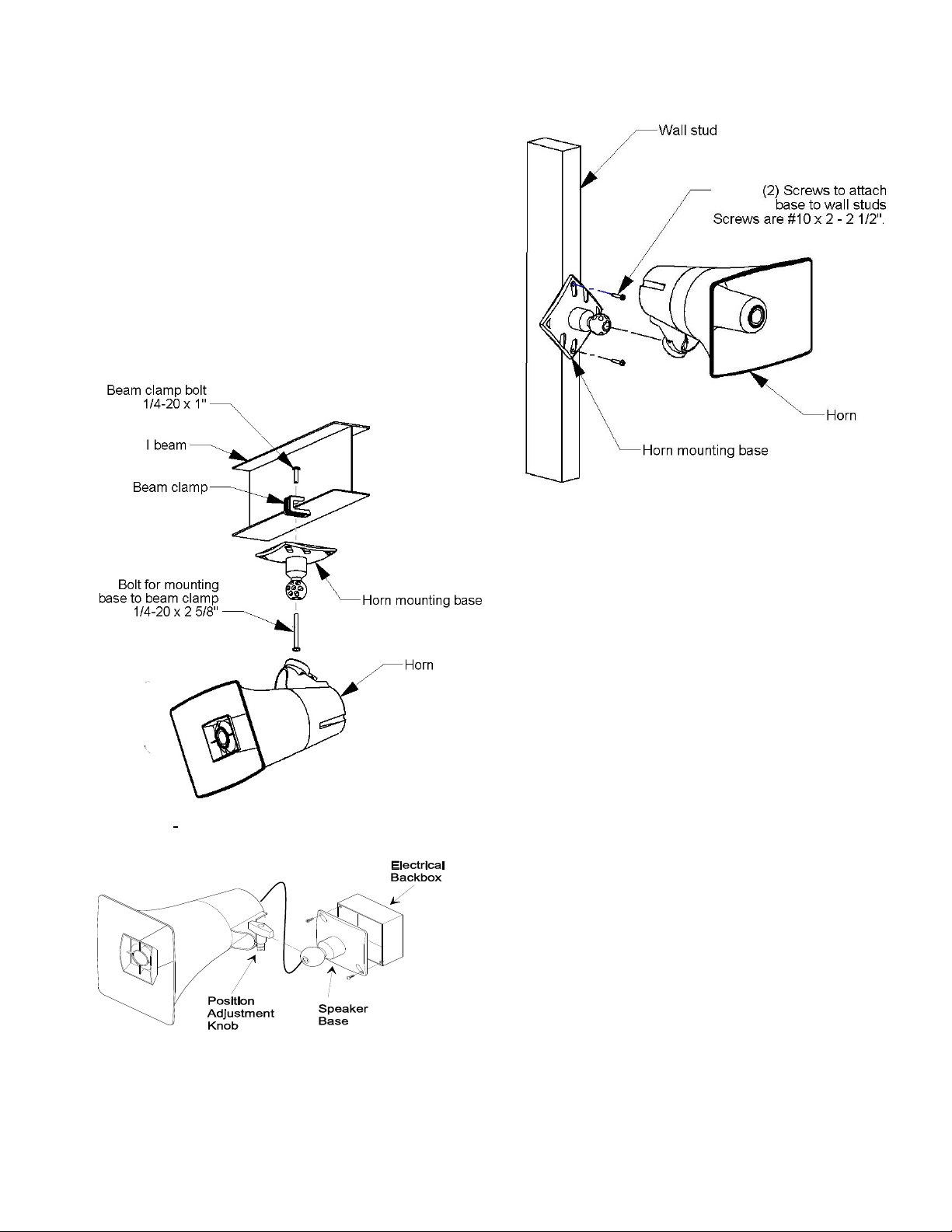
The base has holes punched for a
double-gang square box, but by punching
out additional knockout holes, the base can
be mounted to a single-gang or octagon box
See Figure 2.
Mount the base to wall studs using the two
holes provided. Knockout holes are
provided for punch out should additional
holes be desired. See Figure 3.
The horn may be rotated or moved up and down
to obtain the desired position by loosening the
position adjustment knob at the bottom of the
unit approximately one turn. Make required
adjustments and re-tighten knob.
Figure 1. Mounting to a Beam with a “C” Clamp
Figure 2. Mounting to an Electrical Backbox
Figure 3. Mounting to a Wall Stud
Interconnections
The only method of powering the VIP-130AL-IC
IP Paging Horn is via a Power over Ethernet
(PoE) switch or power injector meeting the
802.3af specification.
Make all required signal connections before
connecting to Ethernet switch or power injector
meeting the 802.3af specification. Power is
supplied to the horn assembly via the Network
Interface
Signal Connections
Audio output connection is made from the Signal
Output. The RJ-45 connector on the horn is
connected directly to the RJ-45 Signal Output
socket on the IP Link. If additional length is
required, any standard T568B extension may be
used. See Figure 4.
Network Connection
The Network Interface has one RJ-45 network
connector. Use a standard Ethernet patch cable
to connect the Network Interface to an Ethernet
switch.
2 947819
Page 3

Status Indicator Lights
The VIP-130AL-IC has 2 status indication lights
located on network jack.
Green LED: (Link) Indicates Ethernet
connection when illuminated.
Yellow LED: (Activity) Indicator flashes to
indicate network activity.
Setup
The VIP-130AL-IC will automatically acquire an
IP address (using DHCP) and connect to the
InformaCast server when connected to the
network and powered up. Information specific to
your application will need to be programmed into
the InformaCast server. Refer to the
InformaCast documentation for further
information.
TECHNICAL ASSISTANCE
Assistance in troubleshooting is available from
the factory. Call (540) 563-2000 and press 1 for
Technical Support or via email at
support@valcom.com.
When requesting assistance, you should include
all available information. It is strongly suggested
that you go to the website and review the
information at www.valcom.com/informacast.
Valcom equipment is not field repairable.
Valcom, Inc. maintains service facilities in
Roanoke, VA.
Should repairs be necessary, attach a tag to the
unit clearly stating your company name,
address, phone number, contact person and the
nature of the problem. Send the unit to:
Valcom, Inc.
Repair & Return Dept.
5614 Hollins Road
Roanoke VA. 24019
Valcom, Inc. warrants its products only to the original purchaser, for its own use, to be free from defects in materials and workmanship
under conditions of normal use and service for a period of one year from the date of shipment. This Limited Warranty obligation shall be
limited to the replacement, repair or refund of any such defective device within the warranty period, provided that:
1. inspection by Valcom, Inc. indicates the validity of the claim;
2. the defect is not the result of damage, misuse or negligence after the original shipment;
3. the product has not been altered in any way or repaired by others and that factory sealed units are unopened (a service charge plus
parts
and labor will be applied to units defaced or physically damaged);
4. freight charges for the return of products to Valcom are prepaid;
5. all units 'out of warranty' are subject to a service charge. The service charge will cover minor repairs (major repairs will be subject to
additional charges for parts and labor).
This Limited Warranty is in lieu of and excludes all other warranties, expressed or implied and in no event shall Valcom, Inc. be
liable for any anticipated profits, consequential damages, loss of time or other losses incurred by the buyer in connection with
the purchase, operation, maintenance, installation, removal or use of the product. The maximum liability of Valcom under this
warranty is limited to the purchase price of the specific Product covered by the warranty.
Disclaimer. Except for the Limited Warranty provided herein, the product is provided “as-is” without any warranty of any kind whatsoever
including, without limitation, any WARRANTY OF MERCHANTABILITY, FITNESS FOR A PARTICULAR PURPOSE OR NONINFRINGEMENT.
This warranty specifically excludes damage incurred in shipment. In the event a product is received in damaged condition, the carrier
VALCOM LIMITED WARRANTY
3 947819
Page 4

SIDE
RJ45 NETWORK
CONNECTION
HORN
HORN SIGNAL CONNECTION
SIDE
RJ45 NETWORK
CONNECTION
RJ-45
Typical 568B
RJ-45 Jack
CAT 3/5/6
RJ45
BROWN
WHITE/BROWN
GREEN
WHITE/GREEN
ORANGE
WHITE/ORANGE
BLUE
WHITE/BLUE
VM-186
BROWN
BLUE
BROWN
WHITE/BROWN
GREEN
WHITE/GREEN
ORANGE
WHITE/ORANGE
BLUE
WHITE/BLUE
HORN
STANDARD
RJ45 PATCH CABLE
(T568B)
*The Maximum Recommended Distance
From the IP Link to the Horn is 350’.
Figure 4. Audio Connections
4 947819
 Loading...