

Page 1
Installation Manual V14.8
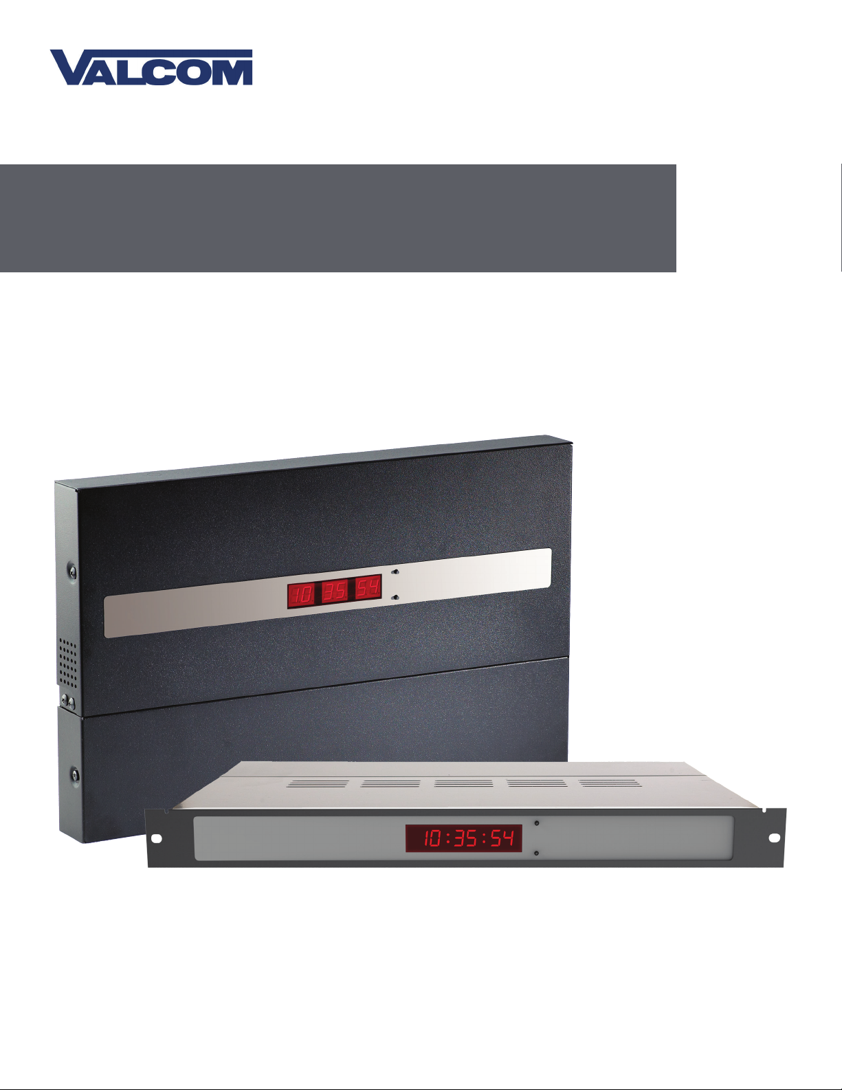
V-WMCA/V-GPSA/V-GPS-TX
Series Master Clock
Current as of November 2016
Valcom, Inc.
5614 Hollins Road
Roanoke, VA 24019
USA
P. 540-563-2000
F. 540-362-9800
www.valcom.com
Page 2

V-WMCA/V-GPSA/V-GPS-TX Master Clock
Table of Contents
Valcom, Inc.
5614 Hollins Road
Roanoke, VA 24019
USA
P. 540-563-2000
F. 540-362-9800
www.valcom.com
Table of Contents 2
Important Safety Instructions 3
System Preparations 4
Installing a Master Clock
- Wall Mount 6 - 8
- Rack Mount 9 - 11
- Remote Antenna for Rack Mount 12 - 15
- GPS Antenna (Optional) 16 - 18
- GPS Antenna with Surge Protector (Optional) 18
Inputs and Outputs
- NTP Server 19
- Sync-Wire 20 - 26
- 2-Wire Digital 27 - 28
- Once-a-Day Pulse 29
- Email Alerts 49
- System Settings 50-51
- Synchronization 52-53
- IP Settings 54
- NTP Servers 55
- IP Status 56
- Clock Features 57
- Database Maintenance 58
NTP Server Upgrade 59
Support - Frequently Asked Questions and Troubleshooting 60-62
Compliances 63
Warranty 64
Basic Configuration
- DHCP and Static IP 30
- Web Interface 31 - 35
Manual Controls 36 - 41
Error Lights on LED Display 42
Wireless System Setup 43 - 44
Web Interface
- Log In 45
- Date/Time 46
- Individual Settings 47
- DST (Daylight Saving TIme) 48
Mandatory for ALL systems
(including wireless and GPS)
Mandatory only in systems
that use GPS time
Mandatory only for master
clocks with a transmitter for a
wireless system
Manuals may change without prior notice
2
Page 3
Valcom, Inc.
5614 Hollins Road
Roanoke, VA 24019
USA
P. 540-563-2000
F. 540-362-9800
www.valcom.com
Important Safety Instructions
VERY IMPORTANT:
KNOW YOUR COMMUNICATION PROTOCOL
This master clock is designed to support multiple communication protocols. To run any clock system
properly, the master clock requires the correct wiring format. It is very important that you only follow the
wiring instructions appropriate to your system’s communication protocol. For example, you should not
try to set up an RS485 system by following instructions for a Sync-Wire system. Failure to use the correct
wiring and protocols for your system may damage the hardware.
DANGER
! !
SHOCK HAZARD
,
• Keep the electricity to this device turned
OFF until the clock installation
is complete.
• Do not expose the clock movement to
water, or install the clock in a location
where it may be exposed to water.
H
|
NOTICE
• Do not install the clock outdoors.
Damage to the clock if placed outdoors
voids the warranty.
• Do not hang objects from the clock or
clock mounting parts. The clocks are not
designed to support the weight of other
objects.
• The clock face and housing may
be cleaned with a damp cloth or
disinfectant. Test other cleaning products
on a small part of the clock housing
before attempting to use on the rest of
the clock. Avoid bleach and chemicals
known to dissolve plastics.
WARNING
FIRE HAZARD
• Always follow your national and regional
electrical codes or ordinances.
• The AC power circuit for the clock must
be attached to a circuit breaker that can
be reset by the user.
PHYSICAL INJURY HAZARD
• If you are standing on an object while
installing your clock, make sure that the
object can support your weight, and will
not sway or move as you stand on it.
• Take precautions to avoid injury by
potential safety hazards near the point
of installation including (but not limited
to) heavy machinery, sharp objects, hot
surfaces, or exposed cables carrying an
electric current.
• Follow all mounting instructions exactly
as stated in this manual. Failure to do so
may result in the device falling off the
point of installation.
• Packaging materials and mounting items
include plastic bags and small pieces,
which pose a suffocation hazard to
young children.
3
Page 4

Valcom, Inc.
Valcom, Inc.
5614 Hollins Road
5614 Hollins Road
Roanoke, VA 24019
Roanoke, VA 24019
USA
USA
P. 540-563-2000
P. 540-563-2000
F. 540-362-9800
F. 540-362-9800
www.valcom.com
www.valcom.com
System Preparations
Identify an appropriate location to install the master clock.
The location should be accessible to the installer, and should be easily able to access its time base. This
means that:
1) This master clock can receive NTP time from any NTP server over a Local Area Network (LAN) as a
standard feature. If NTP is being used as the master clock time source, then the master clock must be
installed in a place that allows it to connect to a network router/switch with CAT5 or CAT6 network cables.
2) The master clock may receive GPS time if it was ordered with an optional GPS receiver module. In this
case the master clock will include a built in GPS receiver module, a GPS cable, and a GPS dome antenna.
The GPS antenna must be installed on the facility’s roof. The master clock should be installed so that the
GPS cable can reach between master clock and the GPS antenna.
3) If the application requires this master clock to receive time data from a third-party master clock, then
this master clock should be installed close enough to the third-party clock that the user can run data wires
between both clocks. Research your communication protocol and provide an appropriate wire gauge and
length to connect both master clocks.
If the master clock is being used to operate a wireless clock system, then there are
additional requirements:
1) The master clock transmitter or Remote Antenna must be placed in a location where the signal is not
interfered with or blocked. Be aware of large structures made of stone, concrete, bricks, or sheet metal
as these materials will block a wireless signal. The installer should also be aware of other objects that may
cause interference to the transmission including, but not limited to, large tanks of salt water, old microwave
ovens, and large industrial machines.
2) The master clock transmitter or remote antenna must be within range of at least one wireless secondary
clock or wireless repeater. If all of the secondary clocks are positioned beyond the range of the master
clock’s transmitter, then the master clock must be connected to the local area network, and a network
repeater must be installed. The maximum transmission distance of the master clock transmitter in an
unobstructed, open space is 3300 feet (1000 meters). Obstructions will reduce this distance, particularly
obstructions made of the materials mentioned in the previous paragraph.
4
Page 5
Installing a Master Clock - Wall Mount
Included in Package
Valcom, Inc.
5614 Hollins Road
Roanoke, VA 24019
USA
P. 540-563-2000
F. 540-362-9800
www.valcom.com
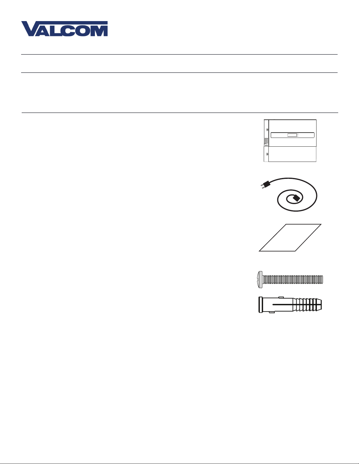
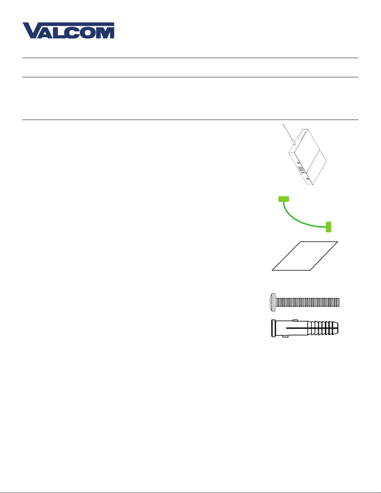
Description
Quantity
Master Clock
Power Cable
(E - PWR- CBL- K IT-1)
Paper Mounting Template
(M-23-MTEMP-1)
Included in Mounting Kit (M-SURF-MNT-KIT1)
Picture
1
1
1
#10-1.5 Sheet Metal Screw
#10 Wall Anchors
Please Note: A user will also have to provide a Phillips-head screwdriver, a ruler, a level, and a drill capable of creating #10 sized holes into the wall.
4
4
5
Page 6
Installing a Master Clock - Wall Mount
Valcom, Inc.
5614 Hollins Road
Roanoke, VA 24019
USA
P. 540-563-2000
F. 540-362-9800
www.valcom.com
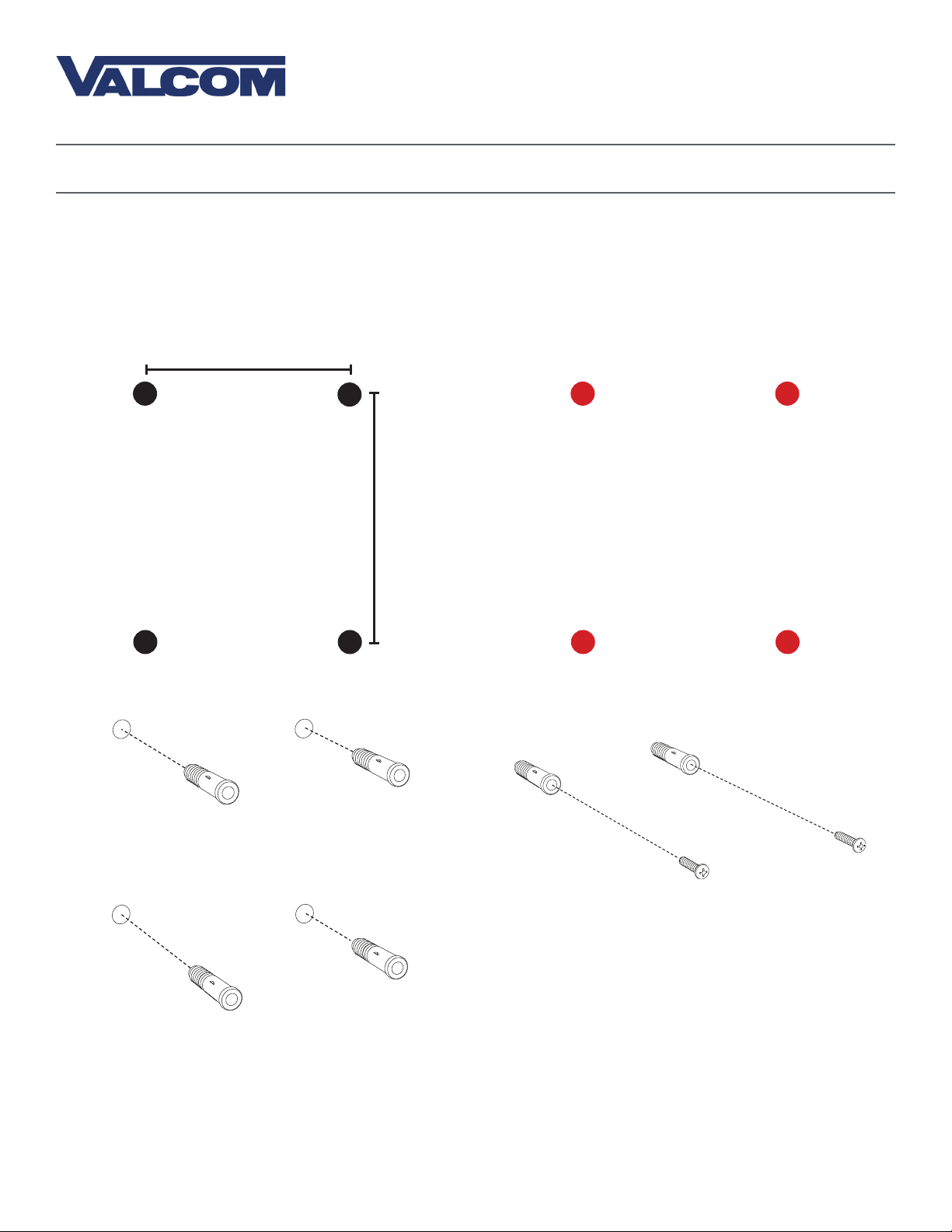
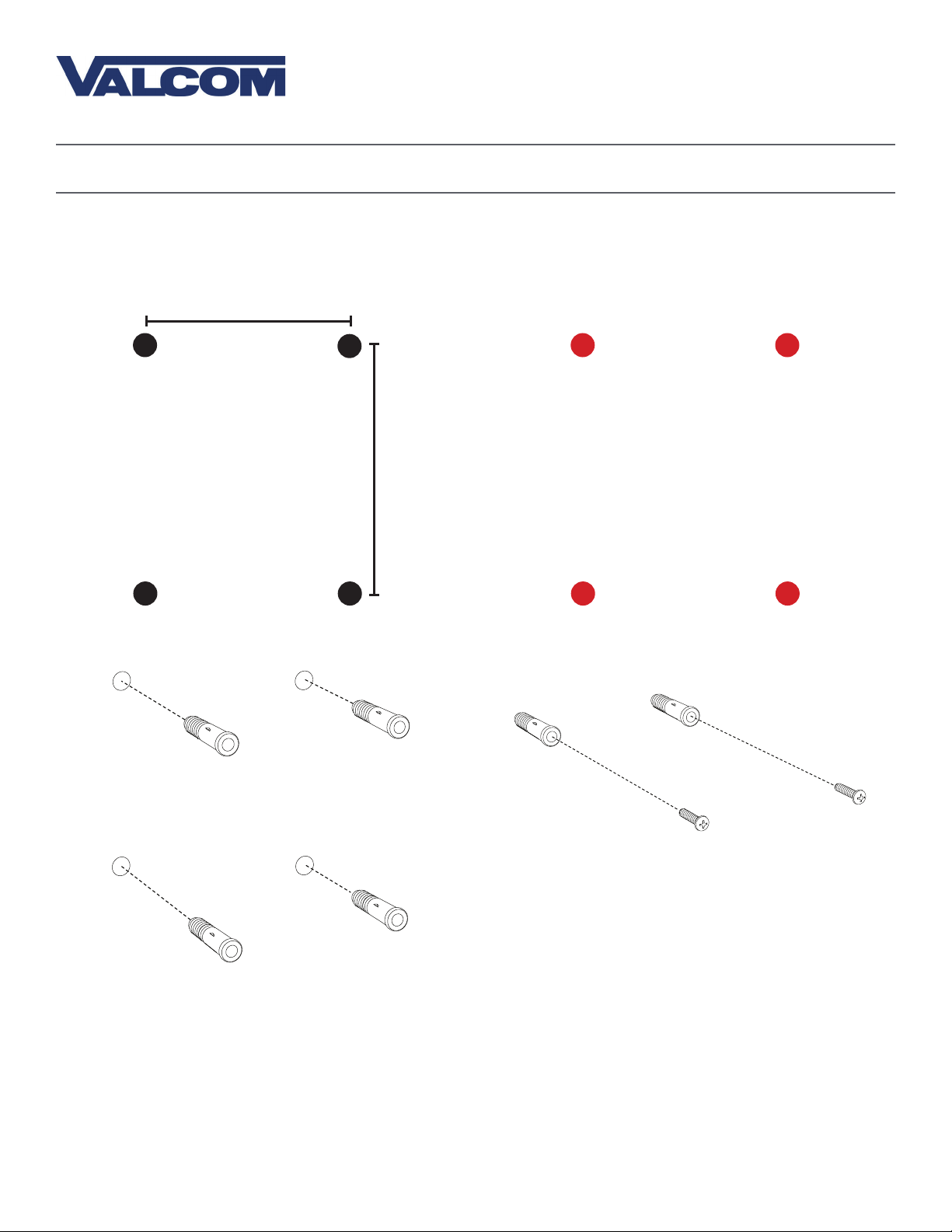
1) Use a ruler, a level, and the provided template to
mark four points on the wall.
16 and 3/8in (41.6cm)
1
6 and 7/8in
(17.5c m)
2) Use a drill to drill holes into the wall at the
marked locations.
2
3) Insert the wall anchors into the holes.
3
4) Insert the sheet metal screws into the top two
wall anchors.
4
6
Page 7
Valcom, Inc.
5614 Hollins Road
Roanoke, VA 24019
USA
Installing a Master Clock - Wall Mount
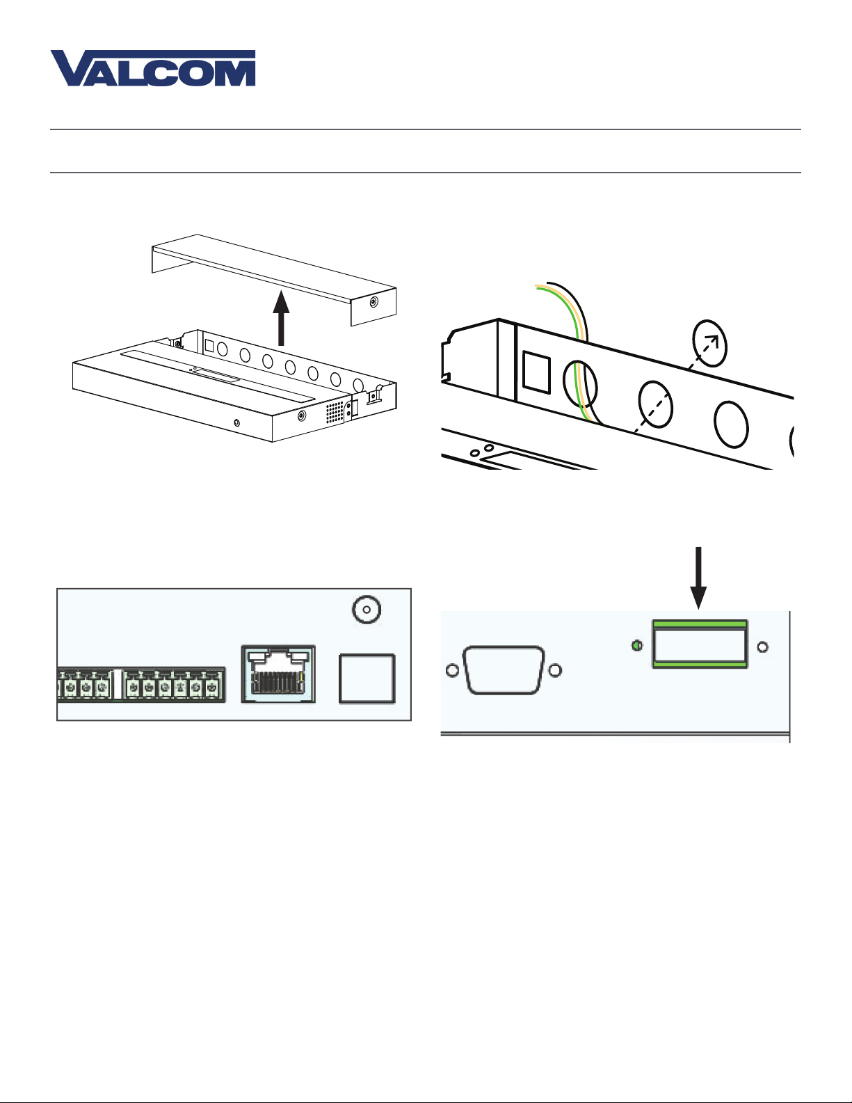
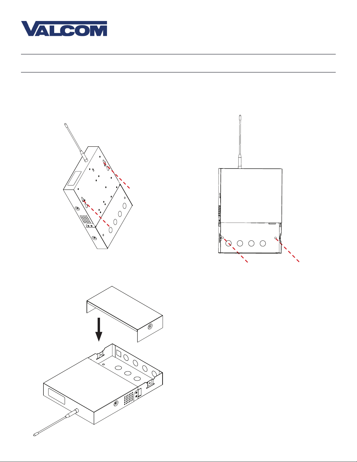
5) Unscrew the bottom panel from the clock. 6) Remove the metal punch-outs so that cables can
be installed. Thread the cables through the
punch-out holes.
P. 540-563-2000
F. 540-362-9800
www.valcom.com
5
7) Connect the input/output cables to their
corresponding sockets. Refer to the sections in this
manual labeled “Inputs” and “Outputs” for details
on each input and output method.
7
6
8) Attach the power cables to the appropriate port
on the clock.
8
7
Page 8
Installing a Master Clock - Wall Mount
Valcom, Inc.
Valcom, Inc.
5614 Hollins Road
5614 Hollins Road
Roanoke, VA 24019
Roanoke, VA 24019
USA
USA
P. 540-563-2000
P. 540-563-2000
F. 540-362-9800
F. 540-362-9800
www.valcom.com
www.valcom.com
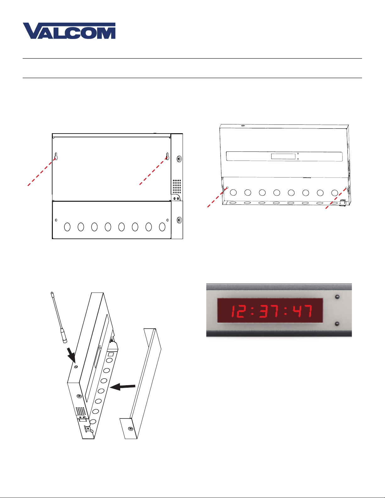
9) Hang the master clock on the wall screws. Do
this by lining the screws up with the keyhole slots
on the bottom of the box, and slipping the slots on
top of the screws.
9 10
11) Use a screwdriver to reattach the master clock
bottom panel. If your master clock has a wireless
signal antenna, attach it to the port on top of the
hardware case.
10) Pass the remaining two screws through the
holes in the bottom compartment and into the
wall anchors.
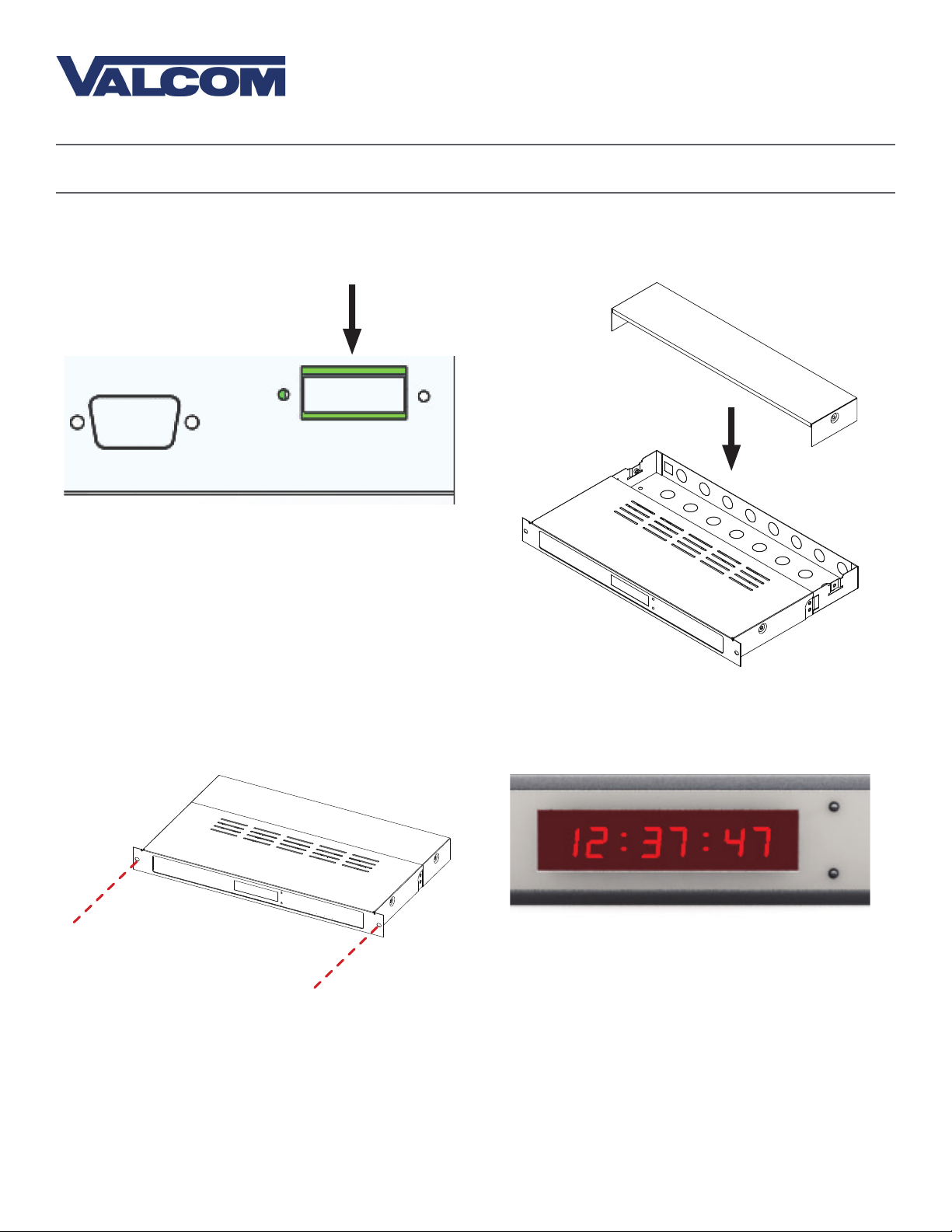
12) Power the master clock. If the master clock has
been powered, the 7-segment LED screen on the
face of the master clock should illuminate.
1211
*REFER TO THE SECTION “BASIC CONFIGURATION - DHCP AND STATIC
IP” FOR FURTHER INSTRUCTIONS
8
Page 9
Installing a Master Clock - Rack Mount
Included in Package
Included in Package
Valcom, Inc.
5614 Hollins Road
Roanoke, VA 24019
USA
P. 540-563-2000
F. 540-362-9800
www.valcom.com
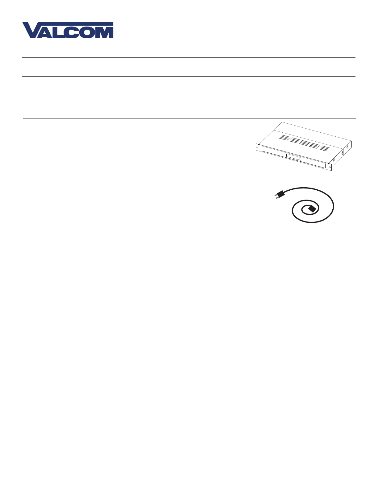
Description
Master Clock
Power Cable
(E - PWR- CBL- K IT-1)
Please Note: A user will also have to provide a Phillips-head screwdriver, a server/network cabinet, and the screws and bolts needed to attach the master
clock to the rack.
Quantity
1
1
Picture
9
Page 10
Installing a Master Clock - Rack Mount
Valcom, Inc.
5614 Hollins Road
Roanoke, VA 24019
USA
P. 540-563-2000
F. 540-362-9800
www.valcom.com
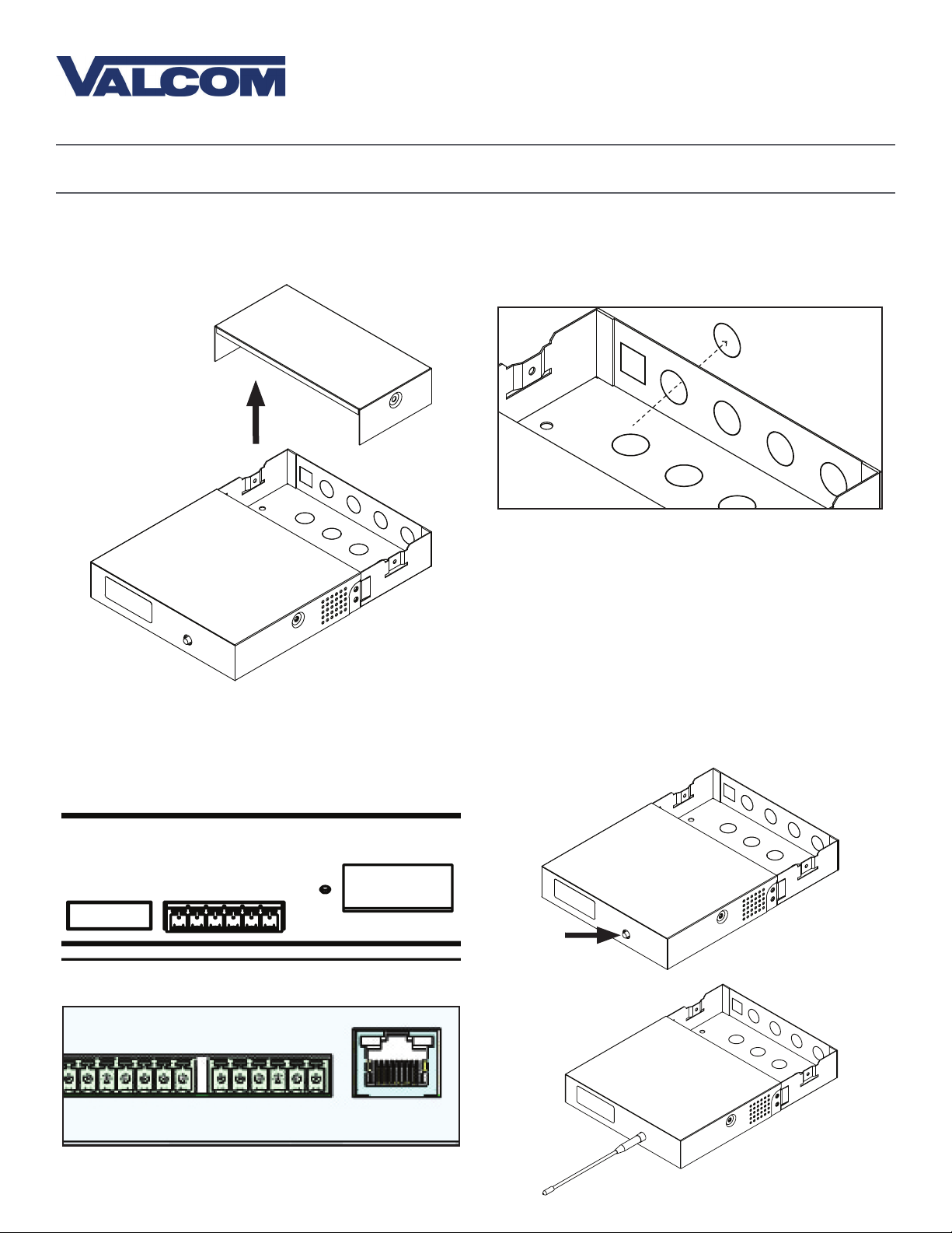
1) Thread any necessary cables through the back of
the network cabinet, including the cables for power,
inputs, outputs, and the remote antenna if
it applies.
1
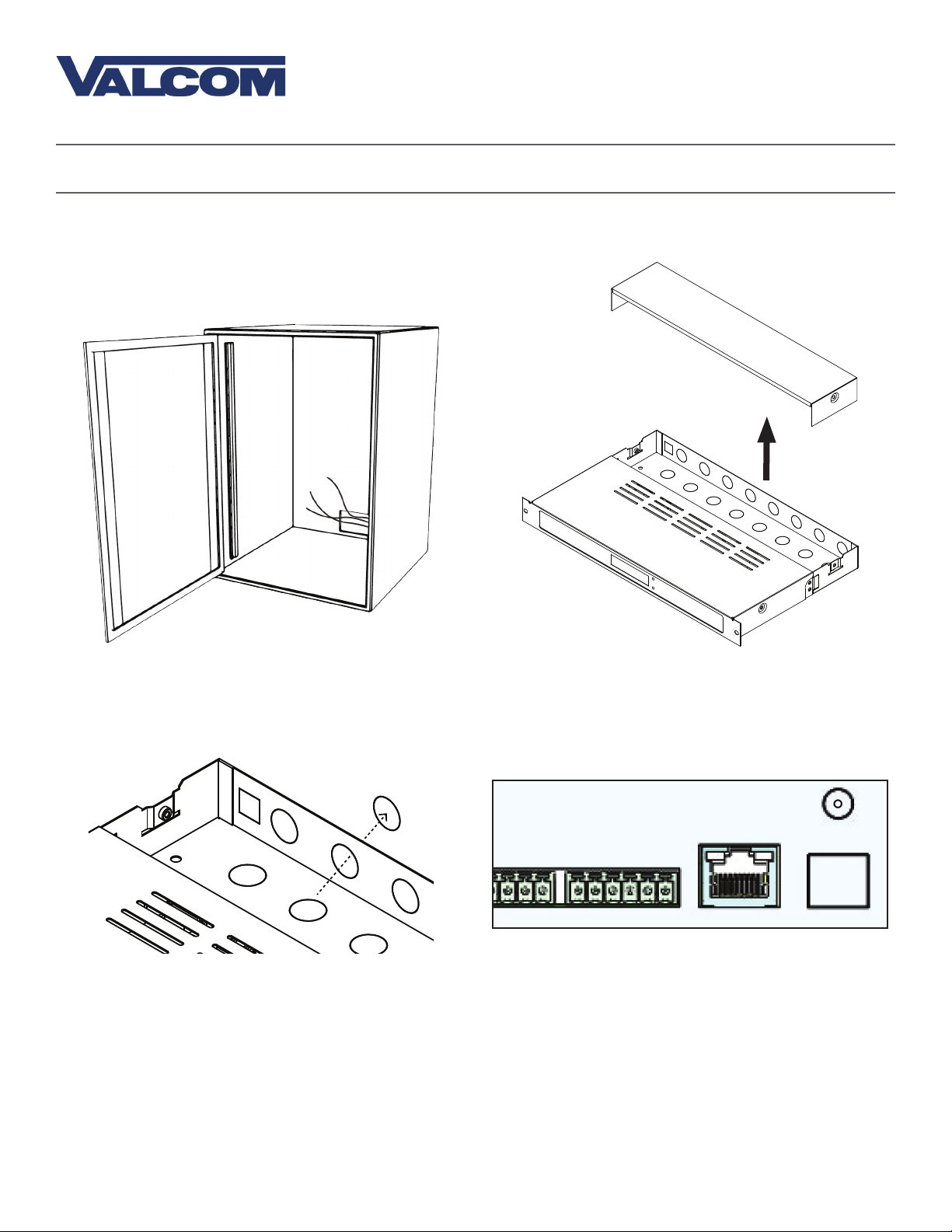
3) Remove the metal punch-outs so that cables can
be installed. Thread the cables through the
punch-out holes.
2) Unscrew the back panel from the master clock.
2
4) Connect the input/output cables to their
corresponding sockets. Refer to the sections in this
manual labeled “Inputs” and “Outputs” for details
on each input and output method.
3
4
10
Page 11
Installing a Master Clock - Rack Mount
Valcom, Inc.
5614 Hollins Road
Roanoke, VA 24019
USA
P. 540-563-2000
F. 540-362-9800
www.valcom.com
5) Attach the power cables to the appropriate port
on the master clock.
5
6) Use a screwdriver to reattach the master clock
bottom panel.
6
7) Install the master clock in the network rack by
inserting screws through the two holes positioned
on either side of the master clock.
7
8) Power the master clock. If the master clock has
been powered, the 7-segment LED screen on the
face of the master clock should illuminate.
8
*REFER TO THE SECTION “BASIC CONFIGURATION - DHCP AND STATIC
IP” FOR FURTHER INSTRUCTIONS
11
Page 12
Valcom, Inc.
Valcom, Inc.
5614 Hollins Road
5614 Hollins Road
Roanoke, VA 24019
Roanoke, VA 24019
USA
USA
Installing a Master Clock - Remote Antenna for Rack Mount
Included in Package
P. 540-563-2000
P. 540-563-2000
F. 540-362-9800
F. 540-362-9800
www.valcom.com
www.valcom.com
Description
Quantity
Remote Antenna
Remote Antenna Cable
25ft (7.62m) long
Paper Mounting Template
(M-V-MCS-CD1-MTEMP-1)
1
Included in Mounting Kit (M-SURF-MNT-KIT1)
Picture
1
(Not to scale)
1
#10-1.5 Sheet Metal Screw
#10 Wall Anchors
Please Note: A user will also have to provide a Phillips-head screwdriver, a ruler, a level, and a drill capable of creating #10 sized holes into the wall.
4
4
12
Page 13
Valcom, Inc.
5614 Hollins Road
Roanoke, VA 24019
USA
Installing a Master Clock - Remote Antenna for Rack Mount
P. 540-563-2000
F. 540-362-9800
www.valcom.com
1) Use the provided template and a leveling device
to mark four points on the wall.
6 and 15/16in (15.08cm)
1
5 and 3/4in
(14.61cm)
3) Insert the wall anchors into the holes.
2) Use a drill to drill holes into the wall at the
marked locations.
2
4) Insert the sheet metal screws into the top two
wall anchors.
3
4
13
Page 14
Valcom, Inc.
5614 Hollins Road
Roanoke, VA 24019
USA
Installing a Master Clock - Remote Antenna for Rack Mount
P. 540-563-2000
F. 540-362-9800
www.valcom.com
5) Unscrew the bottom panel from the
remote antenna.
5
6) Remove at least one metal punch-out from the
bottom of the remote antenna and thread the
power/communication cables through the hole.
6
7) Attach the power and signal cables to ports 1-6.
Each cable should run to the identically numbered
port on the master clock.
Remote Antenna:
6 5 4 3 2 1
7
Master Clock:
6 5 4 3 2 1
8) Attach the antenna to the output port on top of
the device.
8
14
Page 15
Valcom, Inc.
5614 Hollins Road
Roanoke, VA 24019
USA
Installing a Master Clock - Remote Antenna for Rack Mount
P. 540-563-2000
F. 540-362-9800
www.valcom.com
9) Hang the remote antenna on the wall screws. Do
this by lining the screws up with the keyhole slots
on the bottom of the box, and slipping the slots on
top of the screws.
9
10) Pass the remaining two screws through the
holes in the bottom compartment and into the
wall anchors.
10
11) Reattach the bottom panel.
12) The transmitter will begin to transmit as soon
as it is powered and is receiving time data from the
master clock.
1211
15
Page 16
Installing a Master Clock - GPS Antenna (Optional)
Included in Package
Valcom, Inc.
Valcom, Inc.
5614 Hollins Road
5614 Hollins Road
Roanoke, VA 24019
Roanoke, VA 24019
USA
USA
P. 540-563-2000
P. 540-563-2000
F. 540-362-9800
F. 540-362-9800
www.valcom.com
www.valcom.com
Description
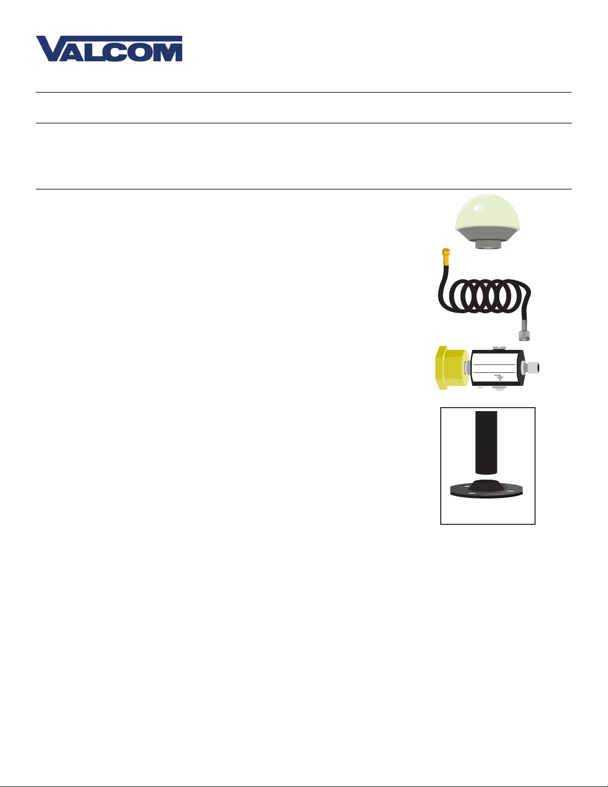
GPS Dome Antenna
GPS Cable
GPS Surge Protector
Quantity
1
1
1
(E-GPS-SURGE-1) Optional accessory
A mounting base and pole must be purchased in order to attach the
antenna to a roof. A dedicated base and pole may be ordered from the
master clock supplier by requesting part number M-GPS-MTG-KIT-1. If the
installer wishes to purchase their own parts, the pole should be capable of
attaching securely to the base and the antenna, which requires either a
1”-14” thread or a 3/4” pipe thread. The pole and base must also each
have a hollow space large enough to allow the GPS cable to pass through
both and attach to the antenna.
Picture
COAXIAL SURGE PROTECTOR
E-GPS-SURGE-1
GROUND
M-GPS-MTG-KIT-1
(Optional Accessory)
If the mounting base and pole are made of metal, then the user must also provide a grounding cable
for the pole. The grounding cable should be 8AWG (8.4mm²) or thicker.
If an optional surge protector is included with the master clock, then the user must provide a second
grounding cable. This cable must also be 8AWG or thicker. Failure to install this grounding cable will
prevent the surge protector from functioning correctly.
Master clocks with the optional GPS Receiver module installed will include a GPS antenna and GPS cable.
The standard cable provided is 75ft (22.9m). A dedicated, longer cable can be ordered through the master
clock supplier by requesting the following part numbers:
E-ANT-CBL-150F-1 150ft (45.7m)
E-ANT-CBL-300F-1 300ft (91.4m)
Please note that Valcom can also provide solutions for projects where a GPS cable longer than 300 feet
(91.4 meters) is required. For more information, please contact your dealer.Using a GPS cable other than
the one provided by your dealer might result in an unreliable time signal. For this reason, using a different
GPS cable than the one provided is strongly discouraged and will void the master clock warranty and support.
16
Page 17
Valcom, Inc.
5614 Hollins Road
Roanoke, VA 24019
USA
P. 540-563-2000
F. 540-362-9800
www.valcom.com
Installing a Master Clock - GPS Antenna (Optional)
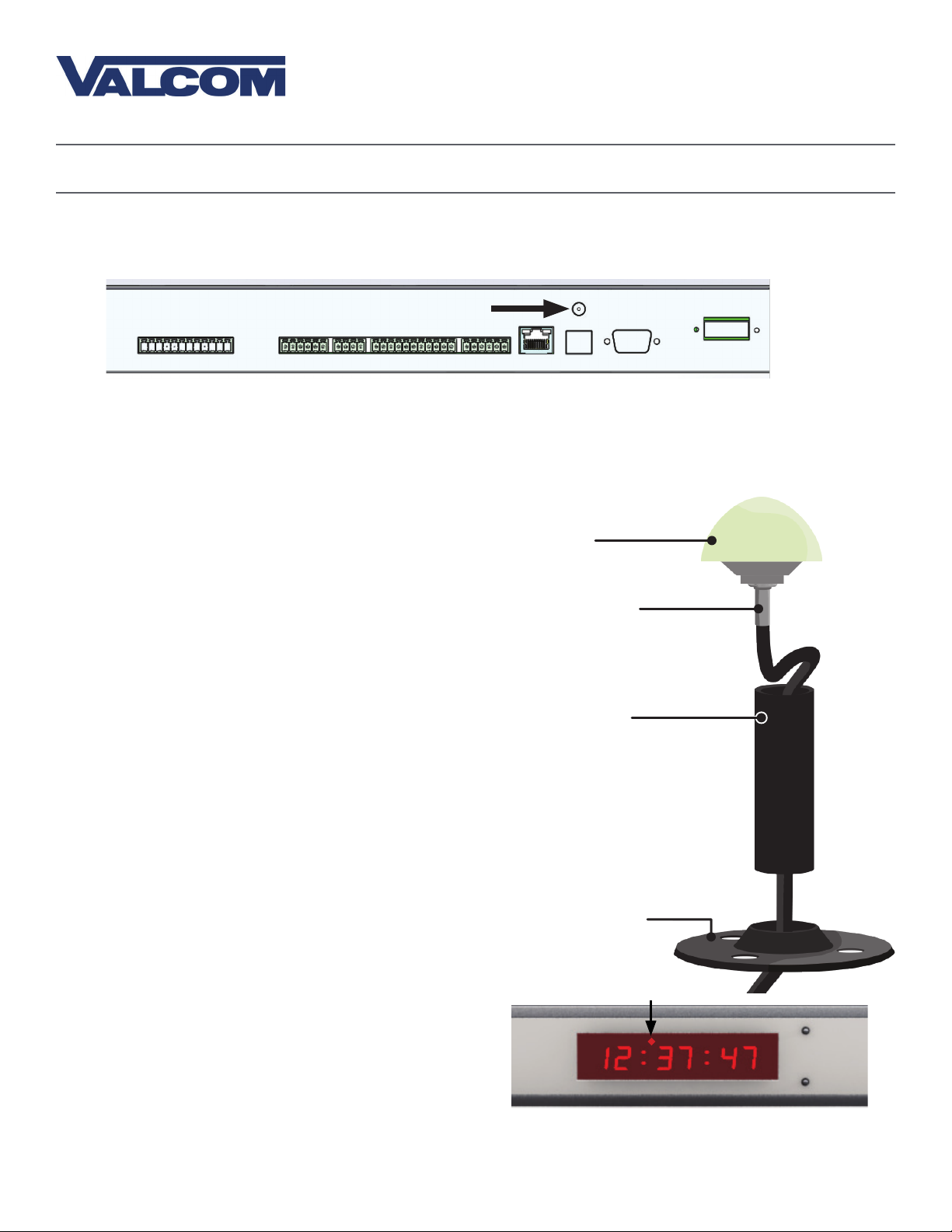
Connecting the GPS cable to the master clock is easy: screw that end of the cable into the dedicated port
on your master clock.
GPS Cable Connector
Continue by connecting the GPS Antenna to a roof. When installing the GPS antenna, pick a location
where the antenna has a clear line-of-sight to as much of the sky as possible, such as on top of the roof.
Avoid locations that are blocked by trees, tall buildings, metal exhaust vents, large rock formations, and
canyon walls. Do not mount the device inside, on, or immediately outside of a window, as these locations
do not promote reliable signal acquisition.
1) Thread the GPS cable through the mounting
bracket and pole.
2) Screw the end of the GPS cable to the connector
on the GPS antenna. The assembly should now
look like the picture on the right.
3) Insert one end of the pole into the mounting
bracket. While holding the base stationary,
twist the pole counter clockwise until it is firmly
screwed into the base.
4) Insert the other end of the pole into the bottom
of the antenna. While holding the pole stationary,
twist the antenna counter clockwise until it is
firmly screwed onto the pole.
5) If you are using a metal pole, attach a grounding
wire to the pole.
6) Attach the completed assembly to the roof.
7) Within 30 minutes, the antenna should acquire a
GPS signal.
GPS Antenna
GPS Cable leading to
Valcom Master Clock
GPS Mounting Pole
M-GPS-MTG-KIT-1
(Optional Accessory)
GPS Mounting Bracket
If your master clock is set to receive GPS time data
as its primary time input, a loss of GPS time data
will cause a red blinking circle to appear above and
to the left of the third digit on the LED time display.
The circle will blink on and off until the signal is regained, or until a different primary input is set (such as
an NTP server). After completing the installation, make sure that this LED is not blinking.
17
Page 18

Valcom, Inc.
5614 Hollins Road
Roanoke, VA 24019
USA
P. 540-563-2000
F. 540-362-9800
www.valcom.com
Installing a Master Clock - GPS Antenna with Surge Protector (Optional)
Customers are offered the opportunity to purchase a surge protector, which is designed to defend the
master clock from a lightening strike to the GPS antenna. The means of connecting the cable to the master
clock is identical to a normal installation, but the procedure for connecting the antenna to the cable and
mount changes:
1) Notice that the surge protector has a tag which
reads COAXIAL SURGE PROTECTOR in the middle,
and GROUND at the bottom.
2) Attach the antenna connector to the PROTECTOR
side of the surge protector.
3) Thread the GPS cable through the mounting
bracket and pole.
4) Screw the end of the GPS cable onto the connector
on the COAXIAL side of the surge protector. The
assembly should now look like the picture on the right.
5) Use a screwdriver to loosen the GROUND screw.
Wrap the exposed end of an 8AWG grounding cable
around the shaft of the screw, then tighten the screw
again. Make sure that the grounding wire runs from
the Surge Protector to the building’s grounding system.
6) Attach the pole to the mounting base. Refer to
step 3 on the previous page.
GPS Antenna
GPS Surge Protector
(Optional accessory)
GPS Surge Protector
to GPS Pole Adapter
GPS Cable leading to
Valcom Master Clock
GPS Mounting Pole
M-GPS-MTG-KIT-1
(Optional Accessory)
E-GPS-SURGE-1
GROUND
COAXIAL SURGE PROTECTOR
7) Insert the pole into the brass cap on the COAXIAL
side of the surge protector. While holding the cap
stationary, twist the pole clockwise until it is firmly
screwed into the cap.
8) If you are using a metal pole, attach a grounding
GPS Mounting Bracket
wire to the pole. The grounding wire should be
12AWG or thicker.
9) Attach the completed assembly to the roof. Use
a method that will allow the pole to remain upright
during severe weather conditions.
10) Attach the other end of the GPS cable to the connector on the master clock if you have not done so
already. Refer to the previous page for a diagram.
11) Within 30 minutes, the antenna should acquire a GPS signal.
If you wish to purchase a surge protector at a later time, call your regional salesperson and ask for the
following part number: E-GPS-SURGE-1
18
Page 19
Valcom, Inc.
5614 Hollins Road
Roanoke, VA 24019
USA
P. 540-563-2000
F. 540-362-9800
www.valcom.com
Inputs - NTP Server
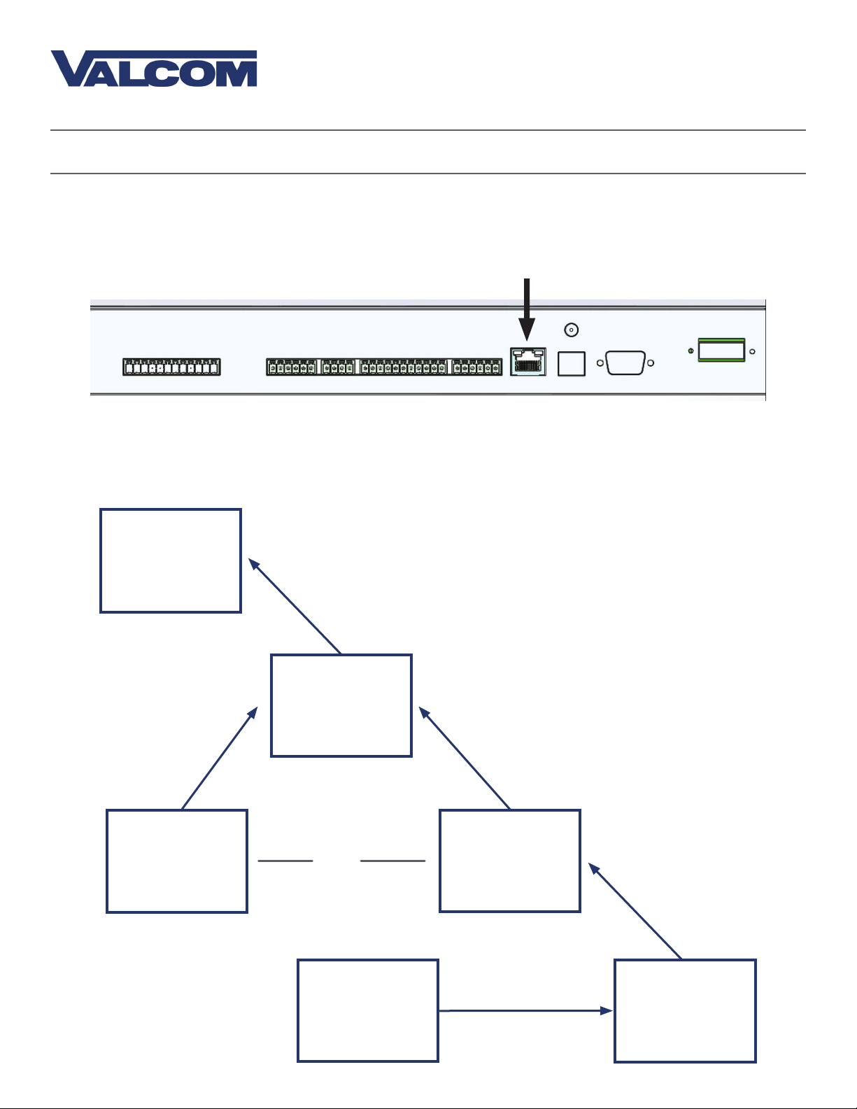
The master clock can receive NTP time over a Local Area Network connected to the Internet. To accomplish
this, the master clock must be connected to the router by a CAT5 or CAT6 Patch Cable with an RJ45
connector. The Ethernet port on the master clock can be identified using the diagram below.
Firewall Ports 80 and 123 must be open to use the master clock on a network.
The connection between the master clock and the router must be a wired connection. V-MCS-CD Master
Clocks do not include a wireless network card for WiFi routers.
MASTER CLOCK
CAT5/CAT6 CABLE
NETWORK
ROUTER / SWITCH
IN-HOUSE NTP
SERVER
OR
MODEM
ONLINE THIRD
PARTY NTP
SERVER
THE INTERNET
19
Page 20
Valcom, Inc.
5614 Hollins Road
Roanoke, VA 24019
USA
P. 540-563-2000
F. 540-362-9800
www.valcom.com
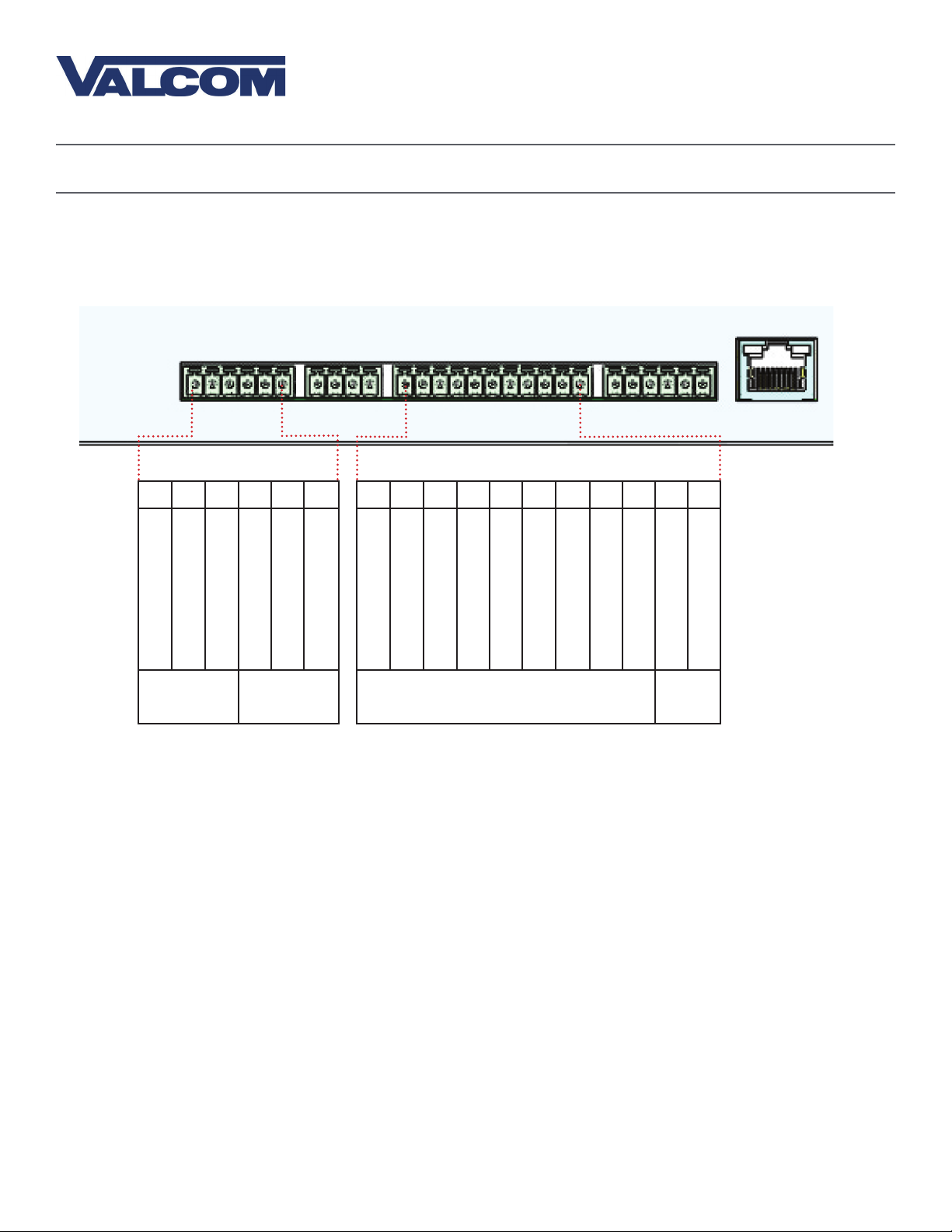
Inputs and Outputs - Sync-Wire
If your master clock is set to receive data through wires from another device as its primary time input, the
wires must be attached to the proper ports on the master clock. The diagram below shows the locations
and the functions of each port.
27 26 25 24 23 22
Normally Open
Relay Common
Clock 1
Sync Relay
Normally Open
Normally Closed
Clock 2
Sync Relay
Normally Common
17 16 15 14 13 12 11 10 9 8 7
Normally Closed
AC/DC Common
120VAC Sync
Sync Inputs
Ducane Reset
24VAC Sync
5VDC Dry Contact
Dukane Min. Pulse
1Rauland Digital
Alarm 12V DC / 24VAC
Alarm Common
Commom
V Out
40ma
+5VDC
Outputs
Consult the wiring diagrams on the following pages for information on how to install wiring specific to
your synchronization method. Relevant port numbers will be listed with each diagram.
IMPORTANT: Your master clock will only accept input from another device if you command it to do so
through the web interface or front panel pushbuttons. For information on how to do this, please see the
section labeled Web Interface - Synchronization
20
Page 21

Inputs - Sync-Wire
59 Minute Correction
Valcom, Inc.
5614 Hollins Road
Roanoke, VA 24019
USA
P. 540-563-2000
F. 540-362-9800
www.valcom.com
Dry Contact Closure 110VAC Interface or
7 17
8
12
N.O.
COM
58 Minute Corrections 1–4
Dry Contact Closure 110VAC Interface or
240VAC Interface
16
110VAC Neutral
240VAC Interface
17
24VAC Interface
15 17
110VAC H o t
24VAC Neutral
24VAC Hot
24VAC Interface
7 17
N.O.
COM
8
12
16
110VAC Neutral
17
110VAC H o t
15 17
24VAC Neutral
24VAC Hot
21
Page 22

Inputs - Sync-Wire
National Time/Rauland
Valcom, Inc.
5614 Hollins Road
Roanoke, VA 24019
USA
P. 540-563-2000
F. 540-362-9800
www.valcom.com
Dry Contact Closure 110VAC Interface or
7 17
Rauland Digital
240VAC Interface
8
12
16
17
N.O.
110VAC Neutral
110VAC H o t
COM
Input Input
11
17
8 24 7
24VAC Interface
15 17
24VAC Neutral
23 22
24VAC Hot
Dig Line
+5V
+5V Out
Dig Out
22
Page 23

Inputs - Sync-Wire
Dukane Digital
Valcom, Inc.
5614 Hollins Road
Roanoke, VA 24019
USA
P. 540-563-2000
F. 540-362-9800
www.valcom.com
7 17
Reset
Minute Pulse
Ground
Once a Day Pulse
Dry Contact Closure
7 17
14
13 8
8
12
N.O.
COM
Fire Alarm Interface Installation
The Fire Alarm Interface allows the user to accept a signal from an existing fire alarm. When the relay is
activated, the master clock will command all of the compatible secondary digital clocks to display “FirE”.
N.O.
COM
8
9
7 10
The fire command is distributed to secondary clocks using the 2-wire, RS485, or Wireless
communication protocols.
23
Page 24

Valcom, Inc.
5614 Hollins Road
Roanoke, VA 24019
USA
P. 540-563-2000
F. 540-362-9800
www.valcom.com
The wiring diagram on the following page applies to Sync-Wire
Systems only
DO NOT USE THE DIAGRAM ON THE FOLLOWING PAGE IF YOUR
SYSTEM USES A SYNCHRONIZATION PROTOCOL OTHER THAN
SYNC-WIRE
NOTE: The Master Clock Sync-Wire Output is set to distribute time using a Once A Day Pulse at 12:00
AM by default. The protocol can be changed through the Web Interface’s Synchronization tab or through
Settings 20 and 25 on the LED menu.
24
Page 25

Outputs - Sync-Wire 115/230VAC
Valcom Master Clock
Valcom, Inc.
5614 Hollins Road
Roanoke, VA 24019
USA
P. 540-563-2000
F. 540-362-9800
www.valcom.com
10 Amp Contact Rating
Clock Circuit
272426
Neutral
Black
White
115 VAC
or
23
Power
Reset
Neutral
Power
Reset
Ground
27 26 25 24 23 22
or*
27 26 25 24 23 22
White
Black
Yellow
Green
115 VAC Valcom Wired Analog Clock
Clock Circuit 1
Clock Circuit 2
* ”or” means one pair of ports or
the other. You cannot, for instance,
use port 23 for reset and 27 for
power, nor can you use 26 for reset
and 24 for power. You must use
the pair 24 AND 23 or the pair
26 AND 27
Neutral
Reset
Power
Neutral
Neutral
Power
Reset
Ground
Ground
J1-1
J1-2
Black
White
Green
White
Black
Yellow
Green
Correction
Power
115 VAC Valcom Wired Digital Clock
Red & Blue Wires are NOT provided by Valcom
115 VAC Valcom Wired Analog Clock
25
Page 26

Outputs - Sync-Wire 24VAC
Valcom Series Master Clock
Valcom, Inc.
5614 Hollins Road
Roanoke, VA 24019
USA
P. 540-563-2000
F. 540-362-9800
www.valcom.com
10 Amp Contact Rating
Clock Circuit
272426
or
23
Neutral
Power
Reset
Black
White
Power
Neutral
Reset
24VDC
Ground
27 26 25 24 23 22
or*
27 26 25 24 23 22
White
Black
Yellow
Green
Clock Circuit 1
* ”or” means one pair of ports or
the other. You cannot, for instance,
Clock Circuit 2
use port 23 for reset and 27 for
power, nor can you use 26 for reset
and 24 for power. You must use
the pair 24 AND 23 or the pair
26 AND 27
24VDC Valcom Wired Analog Clock
Neutral
Reset
Power
Neutral
Ground
Ground
J1-1
J1-3
Yellow
Orange
Green
WhiteNeutral
BlackPower
YellowReset
Green
Correction
Power
24VDC Valcom Wired Digital Clock
Red & Blue Wires are NOT provided by Valcom
24VDC Valcom Wired Analog Clock
26
Page 27

Valcom, Inc.
5614 Hollins Road
Roanoke, VA 24019
USA
P. 540-563-2000
F. 540-362-9800
www.valcom.com
The wiring diagram on the following page applies to 2-Wire Digital
Systems only
DO NOT USE THE DIAGRAM ON THE FOLLOWING PAGE IF YOUR
SYSTEM USES A SYNCHRONIZATION PROTOCOL OTHER THAN
VALCOM’S 2-WIRE DIGITAL PROTOCOL
27
Page 28

Outputs - 2-Wire Digital
Valcom Series Master Clock
18 19
Data In
Valcom, Inc.
5614 Hollins Road
Roanoke, VA 24019
USA
P. 540-563-2000
F. 540-362-9800
www.valcom.com
V-C6124P
+-+-+- +-+-+-
*V-C6124P and the V-CCU are
ordered as a V-VCU.
24 VDC IN24 volt outputs
V-CCU
2 Wire Digital
Output to Clocks
White
Black
V- A 2412 or V- A 2416
Orange
Yellow
V-D2425B or V-D2440 B
White
Black
V- A 2412 or V- A 2416
28
Page 29

Outputs - Once-a-Day Pulse
Valcom Series Master Clock
27 26 25 24 23 22
or*
Valcom, Inc.
5614 Hollins Road
Roanoke, VA 24019
USA
P. 540-563-2000
F. 540-362-9800
www.valcom.com
27 26 25 24 23 22
Intercom, paging system,
or other device
Master Clock Circuit
272426
or
23
Black
Yellow
Power
Reset
* ”or” means one pair of ports or the other. You cannot, for instance, use
port 23 for reset and 27 for power, nor can you use 26 for reset and 24 for
power. You must use the pair 24 AND 23 or the pair 26 AND 27
29
Page 30

Valcom, Inc.
5614 Hollins Road
Roanoke, VA 24019
USA
P. 540-563-2000
F. 540-362-9800
www.valcom.com
Basic Configuration - DHCP and Static IP
NOTE: Firewall Ports 80 (TCP) and 123 (UDP) must be open to use the master clock on a network.
The function of this section is to get a new master clock up and running as quickly as possible. This section
is mandatory for clock systems that will use a Local Area Network as a distribution system, or NTP/SNTP
data as a time source. If your clock system does not require use of your local area network and you do not
wish to use the web interface, you may skip this section and continue with the section labeled
“Manual Controls”.
The master clock is set to DHCP by default. This setting allows the network to automatically assign
an IP address to the master clock. This IP address may be discovered by performing step six below. It is
important to note that this address may change if the network connection is reset.
If you wish to set up the master clock with a crossover cable, then the following series of steps must
be followed. You should check with your network administrator and confirm that the computer connecting
the master clock has an IP address other than 192.168.0.123, a subnet mask of 255.255.255.0, and a
gateway address of 192.168.0.1.
1) Power the master clock.
2) Press the top and bottom buttons simultaneously so that the programming menu appears on the LED
display. If you were successful, the minute digits will disappear and be replaced by dashes.
3) Press the top button again so that the left number advances from 44 to 45, then press the bottom
button once. The LED display should now look like this:
45--cr
4) Repeatedly press the top button until the display shows the time again.
5) Unplug the master clock, wait fifteen seconds, and power the master clock again.
6) Confirm the new master clock IP address by pressing and releasing both buttons simultaneously five
times. Presses 2 through 5 should display the address on the master clock LED display. Pressing and
releasing the both buttons one more time will make the LED display show the time again.
The master clock Web Interface should now be accessible through the IP address 192.168.0.123.
To configure the Web Interface, continue to the section labeled “Basic Configuration--Web Interface”
30
Page 31

Valcom, Inc.
5614 Hollins Road
Roanoke, VA 24019
USA
P. 540-563-2000
F. 540-362-9800
www.valcom.com
Basic Configuration - Web Interface
The function of this section is to quickly configure a new master clock by using the master clock’s web
interface. This instruction set covers NTP and GPS time sources only. For a full list of features available
through the web interface, please see the section labeled Web Interface-Log In. If you are unable to
program the master clock through the web interface, go to the section labeled “Manual Controls” for an
alternative programming method. This section continues from “Basic Configuration--DHCP and Static IP.”
Please complete that section first.
NOTE: Firewall Ports 80 (TCP) and 123 (UDP) must be open to use the master clock on a network.
1) Access the web interface on a web browser (such as Internet Explorer) by entering the master clock IP
address into your browsers address bar. The first three numbers of your master clock’s IP address can be
viewed by pressing and releasing both buttons on the master clock front panel simultaneously. Repeating
this action will show the other numbers of the IP address.
2) Enter the password for the web interface. It should be 6063. Do not use the keyboard number pad. To
submit the password, use your mouse or touchpad to press the Log In button. Pressing the enter/return
key on your keyboard does not submit the password. If the password does not work,
contact tech support.
31
Page 32

Valcom, Inc.
5614 Hollins Road
Roanoke, VA 24019
USA
P. 540-563-2000
F. 540-362-9800
www.valcom.com
Basic Configuration - Web Interface
3) Click on the tab labeled “IP”. If you are configuring a static IP address, follow steps 3A-3F. If you are
configuring a DHCP address, skip to step 4.
B, C
A
D
3A) Confirm that the setting “DHCP” is set to OFF.
3B) Enter a new Gateway IP Address, Subnet Mask, IP Address, and DNS Router Address for your
master clock.
3C) Have your network administrator confirm that all of the other settings comply with your network.
3D) Press the Submit button.
3E) Power down the master clock, wait fifteen seconds, and power it on again.
3F) Access the master clock at the new IP address. If you forgot the new address, repeat step 1 on the
previous page.
32
Page 33

Valcom, Inc.
5614 Hollins Road
Roanoke, VA 24019
USA
Basic Configuration - Web Interface
4) Click on the tab labeled Synchronization.
4A) Select your primary input for time data from the drop-down menu on the upper left.
A B
P. 540-563-2000
F. 540-362-9800
www.valcom.com
C
C
D
4B) Select your backup input for time data from the drop-down menu on the upper right.
4C) If you are using a sync-wire system as an output, select the synchronization method from the drop
down menus for each clock circuit. Add additional timing data if your system requires it.
4D) Press the Submit button.
33
Page 34

Valcom, Inc.
5614 Hollins Road
Roanoke, VA 24019
USA
P. 540-563-2000
F. 540-362-9800
www.valcom.com
Basic Configuration - Web Interface
5) Click on the tab labeled NTP Servers. If you are using NTP as your synchronization source, perform
steps 5A-5E. Otherwise, skip to step 6.
5A) For “Retry failed server after ____ updates”, enter a number of your choice into the blank.
A
C
B
D
E
IF YOU ARE USING AN IN-HOUSE NTP SERVER OR A SINGLE THIRD-PARTY NTP SERVER AS A
TIME DATA SOURCE, FOLLOW 5B-5E. OTHERWISE, SKIP TO 5E
5B) The master clock comes pre-programmed with the IP addresses of ten public (third-party), web-based
NTP servers. Use your mouse to select one of the existing NTP server IP addresses, then press the delete
key on your keyboard. Enter the IP address of the in-house or third-party NTP server into the empty
text box.
5C) Click on the circle next to the in-house NTP server or third party NTP server address to select it.
5D) Click on the box next to “Rotate servers”. If done correctly, the tick mark in the box disappears. In this
mode, the master clock will receive time from the selected NTP server, and will only attempt to contact the
other NTP servers on the list if coomunication with the selected server fails.
5E) Press the submit button.
34
Page 35

Basic Configuration - Web Interface (Continued)
E
D
Valcom, Inc.
5614 Hollins Road
Roanoke, VA 24019
USA
A B C
P. 540-563-2000
F. 540-362-9800
www.valcom.com
6) The following configurations are done in the System Settings tab in the master clock:
6A) *When installing a 2-Wire Clock System the master clock is set to send RS485 time data to
the converter box once every second as standard. This time data rate sent from the master clock to the
converter box can be changed (if needed) by clicking on System Settings and changing the “Send
RS485” to another value.
6B) *When installing an RS485 Clock System the master clock is set to send RS485 time data directly
to the secondary clocks in the system once every second as standard. This time data rate sent from the
master clock to the secondary clocks can be changed (if needed) by clicking on System Settings and
changing the “Send RS485” to another value.
6C) *When installing a Wireless Repeater for a Wireless System, the wireless repeater (Not a Network
Repeater) can simply receive the time via a wireless signal transmitted from a master clock (that is
equipped with a transmitter or from a wireless secondary clock). Simply plug the wireless repeater to local
power (110VAC or 230VAC) and it will repeat the time signal as often as it receives it. A Wireless Repeater
can also obtain time data directly from a master clock through a pair of electrical wires that send the
RS485 time data. The master clock is set to send RS485 time data directly to the wireless repeater once
every second as standard. This time data rate sent from the master clock to the wireless repeater can be
changed (if needed) by clicking on System Settings and changing the “Send RS485” to another value.
6D) GMT Time Offset - The master clock is set to receive GMT (Greenwich Mean Time) also known
as UTC (Coordinated Universal TIme) from an NTP Server (standard) or from a GPS (optional). In order
to have the master clock send the correct local time to the secondary clocks in the system (at the
geographical location of where the clock system is installed), the GMT offset for your time zone must
be set. In order to do that you will need to know the correct GMT offset for your location, for example:
New York is -5 (hours offset from GMT), London is 0 (Hours) and Tokyo is +10 (Hours). This is done in the
System Settings tab of the master clock web interface in the “GMT Offset” field.
6E) In some scenarios, there may be a need to adjust the time displayed by the master clock. If your
application requires such an offset, enter a value (in seconds) into the ‘Bias seconds’ field of the needed
offset. Keep in mind that an offset that is greater than 3600 seconds (1 hour) can be more easily set by
adjusting the GMT offset field.
*Please refer to specific product manuals for more information.
35
Page 36

Valcom, Inc.
5614 Hollins Road
Roanoke, VA 24019
USA
P. 540-563-2000
F. 540-362-9800
www.valcom.com
Manual Controls
The purpose of this section is to get a new master clock up and running using the manual controls on
the front of the master clock. If you would prefer to program the master clock through the convenience
of the web interface, go to the section labeled “Basic Configuration--Web Interface”for an alternate
programming method. This section continues from “Basic Configuration--DHCP and Static IP.” Please
complete that section first before proceeding with the items below.
This master clock should be set to receive accurate time through an NTP server as a standard feature, or
from a GPS receiver as an optional feature. The master clock can also act as a stand-alone master clock,
meaning that it will not receive accurate time and update its time data on a regular basis. Although we
always recommend that the Master Clock receive time data from an accurate time source, if
there is a need for the master clock to act as a standalone device, the Master Clock’s internal real-time
clock should be set manually. This can be done by pressing the top button to advance the hour, and the
bottom button to advance the minute.
Top Button (Hour)
Bottom Button (Minute)
For all other settings, press and release both buttons simultaneously. To return the LED display to showing
the time, repeatedly press the top button until all of the setting codes have been cycled through. The last
code should be 52--00.
The numbers shown on the left are examples. Going down the list and entering every one of
the examples exactly as shown will cause the master clock to malfunction or use incorrect data.
Program your clock setting based off of the instructions in the description on the right.
Setting 1 - Set Year
1 - -1 0
Use the bottom button to scroll from 00 through 99. This permits the user to select
a year from 2000 to 2099.
Setting 2 - Set Month
2 - -1 1
Use the bottom button to scroll from 01 through 12. This permits the user to select
a month from January (01) to December (12).
36
Page 37

Valcom, Inc.
5614 Hollins Road
Roanoke, VA 24019
USA
P. 540-563-2000
F. 540-362-9800
www.valcom.com
Manual Controls
The numbers shown on the left are examples. Going down the list and entering every one of
the examples exactly as shown will cause the master clock to malfunction or use incorrect data.
Program your clock setting based off of the instructions in the description on the right.
Setting 3 - Set Day of the Month
3- -28
10--08
11 - - 0 3
Use the bottom button to scroll from 01 through 31. This permits the user to
select a day from the 1st of the month to the 31st of the month.
Setting 10 - Technical Mode
If the bottom button is used to scroll to option 08. Once Option 8 is selected,
settings 11, 12, and 13 will become accessible.
Setting 11 - RS485 Data Rate
Use the bottom button to scroll from 01 through 12. Each digit corresponds to
a data rate:
12-- E
1 3 - -1 2
20-- 7
1 - Every second
2 - Every 5 seconds
3 - Every 10 seconds
4 - Every 15 seconds
5 - Every 30 seconds
6 - Every minute
Setting 12 - Daylight Saving Time
Press the bottom button to switch between “d’ or “E”
“d” disables Daylight Saving Time
“E” enables Daylight Saving Time
Setting 13 - 12/24 Hour Mode
Press the bottom button to switch between 12 and 24.
12 causes the master clock to display time in 12 Hour mode.
24 causes the master clock to display time in 24 Hour mode.
Setting 20 - Programming Clock Circuit #1 (Output)
Press the bottom button to scroll from 1 to 9. These numbers correspond to
different protocols, specifically:
7 - Every 2 minutes
8 - Every 5 minutes
9 - Every 10 minutes
10 - Every 15 minutes
11 - Every 30 minutes
12 - Every hour
37
Page 38

Valcom, Inc.
5614 Hollins Road
Roanoke, VA 24019
USA
P. 540-563-2000
F. 540-362-9800
www.valcom.com
Manual Controls
The numbers shown on the left are examples. Going down the list and entering every one of
the examples exactly as shown will cause the master clock to malfunction or use incorrect data.
Program your clock setting based off of the instructions in the description on the right.
Setting 20 - Programming Clock Circuit #1 (Output)
20-- 7
1) 58th Minute (1) - The master clock performs an hourly correction that takes 55 seconds and occurs between
XX:58:05 and XX:59:00 of every hour. It also performs two daily corrections: one at 5:00AM and another at
5:00PM. Each daily correction is ten relay cycles, each cycle is 95 seconds long, and the cycles begin at 5:05AM/PM,
5:07, 5:09, 5:11, 5:13, 5:15, 5:17, 5:19, 5:21, and 5:23 respectively.
2) 58th Minute (2) - The master clock performs an hourly correction that takes 60 seconds and occurs between
XX:58:00 and XX:59:00. It also performs two daily corrections: one at 5:00AM and one at 5:00PM. Each daily
correction is made of twelve relay cycles, and each cycle consists of 65 seconds on and 25 seconds off
Press the bottom button to scroll from 1 to 9. These numbers correspond to
different protocols, specifically:
3) 58th Minute (3) - The master clock performs an hourly correction that takes 60 seconds and occurs between
XX:58:00 and XX:59:00. It also performs two daily corrections: one at 5:00AM and one at 5:00PM. Each daily
correction is made of twelve relay cycles, and each cycle consists of 60 seconds on and 120 seconds off.
4) 58th Minute (4) - The master clock performs an hourly correction that takes 55 seconds and occurs between
XX:59:05 and XX:59:00. It also performs two daily corrections: one at 5:00AM and one at 5:00PM. Each daily
correction is made of twelve relay cycles, each cycle is 55 seconds long, and the cycles begin at 5:03:05AM/PM,
5:07:05, 5:11:05, 5:15:05, 5:19:05, 5:23:05, 5:27:05, 5:31:05, 5:35:05, 5:39:05, 5:43:05, and 5:47:05 respectively.
5) 59th Minute - The master clock performs an hourly correction that takes 8 seconds and occurs between
XX:57:54 and XX:58:02. It also performs two daily corrections: one at 5:00AM and one at 5:00PM. Each daily
correction is a single 14 second pulse which lasts from 5:57:54 to 5:58:08.
6) National time & Rauland (1) - The master clock performs an hourly correction that takes 25 seconds and
occurs between XX:00:00 and XX:00:25. It also performs two daily corrections: one at 6:00AM and one at 6:00PM.
Each daily correction is made of twenty four relay cycles consisting of 25 seconds on, followed by 35 seconds off.
7) National Time & Rauland (2) - The master clock performs an hourly correction that takes 25 seconds and
occurs between XX:00:00 and XX:00:25. It also performs two daily corrections at 6:00:25AM and 6:00:25PM. Each
daily correction is a single 24 minute pulse which lasts from 6:00:25AM/PM to 6:24:25.
8) Once a Day Pulse - The master clock relay will close at a specific time and for an amount of time decided by the
clock circuit settings (Settings 21-24 for circuit 1, or 26-29 for circuit 2).
9) Once an Hour Pulse - The master clock relay will close at a specific minute and second of each hour for an
amount of time decided by the clock circuit settings (Settings 22-24 for circuit 1, or 27-29 for circuit 2).
10) Once a Minute Pulse - The master clock relay will close at a specific second of each minute for an amount of
time decided by the clock circuit settings (Settings 23-24 for circuit 1, or 28-29 for circuit 2).
11) Rauland Digital - The master clock will reset the secondary clock to 12:00:00AM, then advance the time on
the secondary clock by one minute for every 0.5 seconds that the Digital line is shorted to ground.
Setting 20 is set to 8 by default.
38
Page 39

Valcom, Inc.
5614 Hollins Road
Roanoke, VA 24019
USA
P. 540-563-2000
F. 540-362-9800
www.valcom.com
Manual Controls
The numbers shown on the left are examples. Going down the list and entering every one of
the examples exactly as shown will cause the master clock to malfunction or use incorrect data.
Program your clock setting based off of the instructions in the description on the right.
Setting 21 - Once a Day Pulse - Clock #1 Circuit - Set Hour
21 - -1 4
This setting only appears if “8” was selected under Setting 20. Press the bottom
button to scroll from 00 to 23. For example, a value of 13 is the same as 1:00PM.
Set to 0 by default.
Setting 22 - Once a Day Pulse - Clock #1 Circuit - Set Minutes
22- -0 0
23- -3 0
This setting only appears if “8” was selected under Setting 20. Press the bottom
button to scroll from 00 to 59. Set to 0 by default.
Setting 23 - Once a Day Pulse - Clock #1 Circuit - Set Seconds
This setting only appears if “8” was selected under Setting 20. Press the bottom
button to scroll from 00 to 59. Set to 0 by default.
24- -05
25-- 1
2 6 - -1 4
27- -00
28 - -3 0
Setting 24 - Once a Day Pulse - Clock #1 Circuit - Set Pulse Duration
This setting only appears if “8” was selected under Setting 20. Press the bottom
button to scroll from 00 to 99. For example, a value of 98 will set a pulse
duration of 1 minute and 38 seconds. Set to 3 by default.
Setting 25 - Programming the Clock #2 Circuit (Output)
Press the bottom button to scroll from 1 to 9. These numbers correspond to the
different protocols listed under Setting 20. Set to 8 by default.
Setting 26 - Once a Day Pulse - Clock #2 Circuit - Set Hour
This setting only appears if “8” was selected under Setting 20. Press the bottom
button to scroll from 00 to 23. For example, a value of 13 is the same as 1:00PM.
Set to 0 by default.
Setting 27 - Once a Day Pulse - Clock #2 Circuit - Set Minutes
This setting only appears if “8” was selected under Setting 20. Press the bottom
button to scroll from 00 to 59. Set to 0 by default.
Setting 28 - Once a Day Pulse - Clock #2 Circuit - Set Seconds
This setting only appears if “8” was selected under Setting 20. Press the bottom
button to scroll from 00 to 59. Set to 0 by default.
29--05
Setting 29 - Once a Day Pulse - Clock #2 Circuit - Set Pulse Duration
This setting only appears if “8” was selected under Setting 20. Press the bottom
button to scroll from 00 to 99. For example, a value of 98 will set a pulse
duration of 1 minute and 38 seconds. Set to 3 by default.
39
Page 40

Manual Controls
3 0 - - 01
Valcom, Inc.
5614 Hollins Road
Roanoke, VA 24019
USA
Setting 30 - Set the Primary Input
Press the bottom button to scroll from 01 to 13. Each value corresponds to the
following inputs:
P. 540-563-2000
F. 540-362-9800
www.valcom.com
00 - Real Time Clock
01 - SNTP
02 - 59 Minute Correction
03 - 58 Minute Correction (1)
04 - 58 Minute Correction (2)
*Do not select value 10 if this master clock is acting as the primary master clock for your
** Selecting value 11 allows access to Settings 34, 35, and 36.
Setting 31 - Set the Secondary Input
31 - - 0 3
32 -5
330000
Press the bottom button to scroll from 00 to 13. Each value corresponds to the
inputs listed for Setting 30.
Setting 32 - Setting the Time Zone Offset
Press the bottom button to scroll from -12 to 12. Each value corresponds to a
time zone relative to Greenwich Mean Time (GMT). For example, New York City
sits in a time zone of GMT - 5, so a master clock being set up in New York City
should be set to value -5.
Setting 33 - Set a Bias Seconds Value
Press the bottom button to add or remove seconds from the time displayed.
The display will scroll from 0 to 7500 (the equivalent of two hours and five
minutes) then will scroll from -999 (the equivalent of -16 minutes, 39 seconds)
up to 0. The values can be made to scroll faster by holding down the
bottom button.
05 - 58 Minute Correction (3)
06 - 58 Minute Correction (4)
07 - National Time/Rauland
08 - Dukane
09 - Rauland Digital
10 - Wireless Repeater*
11 - Once a Day Pulse**
12 - GPS
13 - RS485
3 4 - - 01
35- -3 0
36- -00
Setting 34 - Once a Day Pulse - Input - Set Hour
This setting only appears if “8” was selected under Setting 20. Press the
bottom button to scroll from 00 to 23. For example, a value of 13 is the same
as 1:00PM.
Setting 35 - Once a Day Pulse - Input - Set Minutes
This setting only appears if “8” was selected under Setting 20. Press the
bottom button to scroll from 00 to 59.
Setting 36 - Once a Day Pulse - Input - Set Seconds
This setting only appears if “8” was selected under Setting 20. Press the
bottom button to scroll from 00 to 59.
40
Page 41

Manual Controls
4 0 - -7 6
4 4 - - 01
45--cr
Valcom, Inc.
5614 Hollins Road
Roanoke, VA 24019
USA
Setting 40 - Hours Since the Last Input Signal Was Received
This setting is read-only, and will always be a value from 00 to 99. The value
represents the number of hours since the master clock received an input signal.
Setting 44 - Internet Connection Status.
This setting is read-only, and will always display a value of either 00 or 01. If the
value is 00, the master clock is not connected to the internet. If the value is 01,
the master clock is connected to the Internet.
Setting 45 - Crossover Cable
This setting has two values, “OFF” and “cr”, which can be switched by pressing
the bottom button. If OFF is selected, the master clock is configured to use
DHCP or whatever static IP has been set. If “cr” is selected, then the master
clock will prepare itself to switch to Crossover mode. To fully switch to Crossover
mode, select cr using the bottom button, press the top button to advance to
the next Setting, wait 20 seconds, then power-cycle the master clock. When the
master clock is powered again, it will be configured to a Static IP
of 192.168.0.12 3 .
P. 540-563-2000
F. 540-362-9800
www.valcom.com
50-- E
51-- 5
52- -0 0
Setting 50 - Enter Secondary Clock Diagnostic Mode (Valcom Wired Only)
Use the bottom button to scroll between values “E” and “d”. Value “E” will
enable diagnostic mode for Valcom Wired clocks on the system, while value
“d” will disable diagnostic mode for Valcom Wired clocks.
Setting 51 - Send Diagnostic to Secondary Clocks (Valcom Wired Only)
Pressing the bottom button will scroll through the values 1, 2, 3, 4, 5, and 9.
Each value corresponds to a particular diagnostic. See your secondary clock
manual for details on each diagnostic.
01 - Protocol Verification.
02 - Comprehensive Test
03 - Manufacturer’s Default
04 - Combination of 02 and 03 (button must be pressed on Valcom Wired clocks)
05 - Combination of 02 and 03 (button does not need to be pressed on secondary clock)
09 - Overrides the previous Diagnostic and commands secondary clocks to resume
displaying the time.
Setting 52 - Viewing Duration for Diagnostic Results (Valcom Wired Only)
Press the bottom button to scroll from 00 to 60. Each value represents the
number of minutes that a secondary clock will display the completed diagnostic.
For instance, if a value of 30 is selected, then secondary clocks that have been
sent a diagnostic command by the master clock will continue to show the results
of their diagnostic for 30 minutes.
Pressing the top button one more time will revert the master clock LED display to showing the
time. Any altered settings will be saved to the master clock’s memory.
41
Page 42

Valcom, Inc.
5614 Hollins Road
Roanoke, VA 24019
USA
P. 540-563-2000
F. 540-362-9800
www.valcom.com
Error Lights on LED Display
The display on the master clock features a circular LED above and to the left of each digit. These LEDs will
activate in the event of an error, or to indicate other information. The LEDs have the following meanings:
PM Light. Activates between 12-Noon and
12-Midnight when in 12-hour display mode.
Ethernet cable is disconnected. Activates only if
NTP is selected as an input.
GPS time data is not being received. Activates only
if GPS is the primary input.
DHCP connection failed. Activates only if the
master clock has been set to receive an IP
address from a DHCP server.
The master clock is unable to
communicate with the NTP server
(unable to receive accurate time).
Activates only if NTP data is the
primary input.
Not used.
Repeatedly switches on and off if active
Turns on and remains lit if active
42
Page 43

Valcom, Inc.
5614 Hollins Road
Roanoke, VA 24019
USA
P. 540-563-2000
F. 540-362-9800
www.valcom.com
Wireless System Setup
1. Identify an appropriate location to install the master clock or remote antenna. See the pictures on the
next page for examples.
• The master clock transmitter or Remote Antenna must be placed in a location where the signal will not be
blocked or inhibited. Be aware of large structures made of stone, concrete, bricks, or sheet metal (including
metal network cabinets) as these materials will block a wireless signal. The installer should also be aware of
other objects that may cause interference to the transmission including, but not limited to, large tanks of salt
water, old microwave ovens, and large industrial machines.
• The master clock transmitter or remote antenna must be within range of at least one wireless secondary
clock or wireless repeater. If all of the secondary clocks are positioned beyond the range of the master clock’s
transmitter, then the master clock must be connected to the local area network, and a network repeater must
be installed. The maximum transmission distance of the master clock transmitter in an unobstructed, open
space is 3300 feet (1000 meters). Obstructions will reduce this distance, particularly obstructions made of the
materials mentioned in the previous paragraph.
2. Install the master clock and confirm that it is properly configured and powered on. DO NOT
INSTALL SECONDARY CLOCKS UNTIL THE MASTER CLOCK IS CONFIGURED AND POWERED.
3. Confirm that the antenna has been correctly installed. For surface-mount master clocks, the antenna
should be installed in the socket on top of the master clock. For rack-mount master clocks, the remote
antenna should be plugged into the socket on the back of the master clock. Refer to the Remote Antenna
installation instructions, step 7, for details and a diagram.
4. Power all secondary battery-powered clocks within the same room as the master clock. Wait until the
clock recieves time data from the master clock before taking it to its point of installation. Refer
to the secondary clock manual for detailed steps.
Please be aware:
A master clock equipped with a wireless transmitter will automatically begin to transmit time data every
minute, beginning at the top of the minute.
If a repeater is being directly powered by the facility’s electrical systems, then the repeater will receive time
data and correct within the first 60 seconds, or immediately upon being powered on.
If a wireless secondary clock is being directly powered by the facility’s electrical systems, then the
secondary clock will receive time data and correct within the first 60 seconds, or immediately upon being
powered on.
If a wireless secondary clock is being powered by batteries, then the clock will receive time data and
correct within the first 2 hours (in normal mode) or 4 hours (in economy mode), or immediately upon
being powered on.
If a wireless secondary clock or repeater is not receiving power from the facility’s electrical systems or
batteries, then the clock or repeater will not function at all. Wireless clocks and repeaters ARE NOT
POWERED WIRELESSLY, they only receive time data wirelessly.
If a wireless secondary clock or repeater is powered, but the master clock is not powered, then the wireless
secondary clock or repeater will not receive time data.
43
Page 44

Wireless System Setup
On the right is a Wall/Surface Mount Master Clock
with a built-in transmitter.
Valcom, Inc.
5614 Hollins Road
Roanoke, VA 24019
USA
P. 540-563-2000
F. 540-362-9800
www.valcom.com
On the right is a Rack Mount Master Clock and
Remote Antenna/Transmitter.
The remote antenna must be positioned ABOVE
metal network cabinets to prevent
signal interference.
44
Page 45

Valcom, Inc.
5614 Hollins Road
Roanoke, VA 24019
USA
P. 540-563-2000
F. 540-362-9800
www.valcom.com
Web Interface - Log In
1
2
1. Password - There are two levels of passwords that will enable the user to access web interface features.
The first level is User level programming, which includes features like setting the time, setting the date, and
adding/editing events and schedule changes. The default password for the user level is 1111. The User level
password can be changed from the Technician level. The default Technician level password is 6063 and
provides access to all of the enabled features on the master clock.
3
2. Log In - This button, when pressed, attempts to log into the master clock using the password entered
in the password field.
3. Forgot Password - This button, when pressed, directs the user to the tech support phone number.
NOTE: Firewall Ports 80 (TCP) and 123 (UDP) must be open to use the master clock
on a network.
45
Page 46

Web Interface - Date/Time
1
2
Valcom, Inc.
5614 Hollins Road
Roanoke, VA 24019
USA
P. 540-563-2000
F. 540-362-9800
www.valcom.com
3
1. Time - This field is where the current time is displayed. The time data should be received from an
NTP server as standard or from a GPS receiver as an optional feature. If needed, the time can be edited
manually by clicking within the field, typing the desired time into the field, and pressing the Change
Time button. The time must be entered in 24 hour format HH:MM:SS. For example, if you wish to enter
a time of 1:00 PM, then it must be entered as 13:00:00). If the master clock is receiving input data from
an external source (including SNTP, GPS, or another master clock) then the external source overrides any
changes made to the time.
2. Date - This field is where the current date is displayed. The date should be received from an NTP server
as standard or from a GPS receiver as an optional feature. If needed, the date can be edited manually by
clicking within the field, typing the desired date into the field, and pressing the Change Date button. The
date must be entered in using the format MM/DD/YYYY). If the master clock is receiving input data from
an external source (including SNTP, GPS, or another master clock) then the external source will override any
changes made to the date.
3. Log Out - When pressed, this button returns the user to the Log In page and prevents the user from
entering other tabs until they log in again.
NOTE: The time and date displayed represent the time and date at the time that the page was loaded.
To update the display to show the most recent time and date, press the refresh button on your web
browser once.
46
Page 47

Web Interface - Individual Settings
1
2
3
4
5
6
Valcom, Inc.
5614 Hollins Road
Roanoke, VA 24019
USA
P. 540-563-2000
F. 540-362-9800
www.valcom.com
1. Send Number - Allows the user to choose a 4-digit number from 0000 to 9999 to be sent to
applicable digital secondary clocks. This number will appear on the display of whichever digital clock
receives it.
2. Send Number to All Clocks - When checked, sends the 4-digit number from 1 to ALL applicable
digital secondary clocks when the Submit button is pressed. The number will appear on the clock for 20
seconds, then the clock will return to displaying the time.
3. Clock Number - Allows the user to send the 4-digit number from 1 to a specific digital secondary clock
when the Submit button is pressed. A secondary clock’s number may be set through the digital clock
sbdconfig interface* or front panel buttons**. See the digital clock manual for more information.
4. Zone Number - Allows the user to send the 4-digit number from 1 to all digital secondary clocks
within a preset, named region when the Submit button is pressed. A digital clock’s “zone” may be set
through the digital clock sbdconfig interface* or front panel buttons**. See the digital clock manual for
more information.
5. Set Bell Indicator - Clicking on a box causes all the digital clocks in the system to display “BELL” when
the selected zone is activated.
6. Submit - This button, when pressed, saves and applies all the selections to the Master Clock.
*sbdconfig is only available for 3200/3300 models of the Valcom Wired and Wireless digital clocks.
** Button-based configuration is only available for 3300 models of the Valcom Wired and Wireless digital clocks.
47
Page 48

Valcom, Inc.
5614 Hollins Road
Roanoke, VA 24019
USA
P. 540-563-2000
F. 540-362-9800
www.valcom.com
Web Interface - DST (Daylight Saving Time)
1
2
3
1. Daylight Saving Time Selection - This drop down list gives four options for configuring Daylight
Saving Time:
• None - When this option is selected, Daylight Saving Time is not applied.
• By Country - When this option is selected, the Daylight Saving Time can be chosen based on the established
DST laws of a country. For instance, if the United States is selected in the Configuration Area, then the master
clock will add an hour on the second Sunday in March, and subtract and hour on the first Sunday in November.
This is the default setting. North American Group is the default group. Under these settings,
DST begins on the second Sunday in March and ends on the first Sunday in November.
• Day of Month - When this option is selected, the Daylight Saving Time can be chosen based on the date and
time that it begins and ends. For instance, it can be set to begin on March 28th at 2AM and end on
Novermber 1 at 2AM.
• Day of the Week in begin on the second Sunday in March at 2AM, and end on the first Sunday in
November at 2AM.
The selection is made by selecting the option from the drop-down list, then pressing the “Select” button.
2. Configuration Area - This area contains the submenu for configuring whichever option was selected
under “Daylight Saving Time Selection”
3. Submit - This button, when pressed, saves and applies the Daylight Saving Time settings.
48
Page 49

Web Interface - Email Alerts
1
2
3
4
5
6
Valcom, Inc.
5614 Hollins Road
Roanoke, VA 24019
USA
7
P. 540-563-2000
F. 540-362-9800
www.valcom.com
8 9
1. Email Recipient - This field is where the user name of the e-mail recipient is entered. Do not enter the
domain and suffix. If the full address is johnsmith@domain.com, then johnsmith should be entered in this field.
2. Email Domain - This field is where the user enters the domain name of the email recipient. Do not
enter the user name or the @. If the full address is johnsmith@domain.com, then domain.com should be
entered in this field.
3. Email Server - This field is where the user enters the address of the local outgoing email server for
the email recipient. Consult with the network administrator for the email server address. Emails are sent
using SMTP.
4. NTP Synchronization Timeout - When the box is checked, the master clock checks the amount of
time since the last NTP signal has been received. If the amount of time recorded exceeds the amount of
time specified in the box to the right, then the master clock sends an email alert. If this option is selected,
the value in the box should be 1 or higher.
5. GPS Synchronization Timeout - When the box is checked, the master clock tests the internal GPS
module to confirm that it is receiving a valid time signal from the GPS antenna. If the module fails the
check for an amount of time exceeding the value specified in the box to the right, then the master clock
sends an email alert. If this option is selected, the value in the box should be 1 or higher.
6. Master Restart - When the box is checked, the master clock sends an email alert every time that it is
restarted (including after power loss or deactivation by the user).
7. Fire Alarm - When the box is checked, the master clock sends an email whenever the master clock
receives a signal that the fire alarm has been activated. The fire alarm must be properly wired to the master
clock for this to work. For wiring instructions, refer to the section of this manual labeled “Inputs - SyncWire: Fire Alarm Interface Installation.
8. Submit - When the button is clicked on, all of the settings on the page are saved and applied.
9. Test Send - When the button is clicked on, the master clock will send an email to whichever address
has been entered. It does NOT save the settings.
49
Page 50

Web Interface - System Settings
1
2
Valcom, Inc.
5614 Hollins Road
Roanoke, VA 24019
USA
P. 540-563-2000
F. 540-362-9800
www.valcom.com
3
1. User Password - This field allows the user to enter a new password for user-level programming. Users
may view every tab, but cannot change every setting. The password must be entered once in the User
Password field and once in the Confirm Password field, otherwise the password will not be changed when
the Submit button is pressed. The password must be at least four characters long, and may only
use the numbers 0-9.
2. Technician Password - This field allows the user to enter a new password for technician-level
programming. Technicians may view and change the content on every tab. The password must be entered
once in the Technician Password field and once in the Confirm Technician Password field, otherwise the
password will not be changed when the Submit button is pressed. The password must be at least four
characters long, and may only use the numbers 0-9.
3. Send RS485 Data Every - These fields allow the user to enter values for how often RS485 time data
will be sent by the master clock.
NOTE: Passwords may only consist of numbers 0 through 9. Do not use any symbols, or characters from
languages other than English.
50
Page 51

Web Interface - System Settings (Continued)
4
5
6 7
Valcom, Inc.
5614 Hollins Road
Roanoke, VA 24019
USA
P. 540-563-2000
F. 540-362-9800
www.valcom.com
1. Bias Seconds - This field allows the user to add or subtract seconds from the time being sent to
secondary clocks. This is useful for regions that offset their time from GMT by fractions of an hour (Central
Australia, India, and Newfoundland, among others). Technicians may enter a value between -9999 and
9999 (equal to 2 hours, 45 minutes, and 49 seconds either way). Some useful values include 900 (15
minutes) 1800 (30 minutes) and 2700 (45 minutes).
2. GMT Offset - This field sets the time zone relative to Greenwich Mean Time (GMT) also known as
Coordinated Universal Time (UTC). Under this system, time zones in Asia, Australia, and most of Africa and
Europe have a positive hour offset, while time zones in North and South America have a negative hour
offset. Consult the table below for some examples:
LOCATION LOCAL TIME OFFSET VALUE
Los Angeles (USA) / Vancouver (Canada) 4:00 AM -8
Phoenix (USA) / Denver (USA) 5:00 AM -7
Chicago (USA) / Mexico City (Mexico) 6:00 AM -6
New York City (USA) / Toronto (Canada) 7:00 AM -5
São Paulo (Brazil) / Buenos Aires (Argentina) 9:00 AM -3
Greenwich/London (UK) 12:00 PM 0
Paris (France) / Berlin (Germany) 1:00 PM 1
Dubai (UAE) / Moscow (Russia) 3:00 PM 3
Hong Kong (China) 8:00 PM 8
Tokyo (Japan) / Seoul (South Korea) 9:00 PM 9
Sydney (Australia) 10:00 PM 10
3. Submit - This button, when pressed, saves the proposed schedule change.
4. Cancel - This button, when pressed, clears all of the fields and does not save any information or changes.
51
Page 52

Web Interface - Synchronization
1 2
Valcom, Inc.
5614 Hollins Road
Roanoke, VA 24019
USA
P. 540-563-2000
F. 540-362-9800
www.valcom.com
1. Input Selection - This drop-down list allows the user to select which service signal the master clock will
depend upon for accurate time. The options include:
NTP 58 Minute Sync_1 National Time_Rauland Once a Day Pulse**
GPS* 58 Minute Sync_2 Dukane Digital RS485
Internal Real Time Clock 58 Minute Sync_3 Rauland Digital
Wireless Repeater 58 Minute Sync_4 59 Minute Sync
*A GPS module must have been purchased as part of your master clock, otherwise the master clock cannot receive time this way. Even if the user purchases
a separate GPS antenna, it will not work without the GPS module.
**If Once a Day Pulse is selected, fields for Hours, Minutes, and Seconds will appear. Enter the time (in 24 hour format; 1:00 PM = 13:00) when the Once a
Day pulse is present. The pulse must last for longer than one second.
2.Backup Selection - This drop-down list allows the user to select which service the master clock will use
as a backup if the primary input fails. If any of the following services are used as the primary input, then
none of the following services may be used as the backup:
59 Minute Sync, 58 Minute Sync (any versions), National Time/Rauland, Dukane Digital, Rauland
Digital, and Once a Day Pulse.
(Example: If 59 Minute Sync is the Primary Input, Rauland Digital may NOT be used as the backup)
52
Page 53

Web Interface - Synchronization (Continued)
Valcom, Inc.
5614 Hollins Road
Roanoke, VA 24019
USA
P. 540-563-2000
F. 540-362-9800
www.valcom.com
3
4
5 6
3. Clock #1 Circuit - This drop-down list allows the user to select the sync-wire output for master clock
Sync-wire Circuit 1. The available output signals are:
59 Minute Sync 58 Minute Sync_4 Once a Day Pulse
58 Minute Sync_1 Rauland Digital Once An Hour Pulse
58 Minute Sync_2 National Time_Rauland_1 Once A Minute Pulse
58 Minute Sync_3 National Time_Rauland_2
4. Clock #2 Circuit - This drop-down list allows the user to select the sync-wire output for master clock
Sync-wire Circuit 2. The available output signals are listed above.
5. Submit - This button, when pressed, saves and applies all the selections to the master clock.
6. Cancel - This button, when pressed, clears any changes made and does not save any data.
53
Page 54

Web Interface - IP Settings
6
Valcom, Inc.
5614 Hollins Road
Roanoke, VA 24019
USA
P. 540-563-2000
F. 540-362-9800
www.valcom.com
1
2
3
4
5
7
8
9 10
1. Gateway IP Address* - This field allows the user to set the Gateway IP address for the master clock.
2. Subnet Mask* - This field allows the user to set the Subnet Mask for the master clock.
3. IP Address* - This field allows the user to set an IP address for the master clock. The web interface may
also be accessed at this address.
4. DNS Router - This field allows the user to set the IP address for the network’s DNS router.
5. DHCP - When set to “on”, allows the master clock to request and apply an IP address from a
DHCP server.
6. Send Status to Monitor on Specified IP - When set to ON, allows the master clock to talk to the
IP Monitor Software at a specific IP address. This is particularly useful for addresses that exist outside of
the master clock’s subnet. IP Monitors on the same subnet may still access the master clock, regardless of
whether this setting is ON or OFF.
7. Monitor IP Address - Allows the user to select the destination address for the unicast mentioned
in setting 6.
8. Device Name - This field allows the user to set the name for the master clock. This name will only
appear on the Web Interface and IP Monitor Software.
9. Submit - This button, when pressed, saves and applies all of the selections to the master clock.
10. Cancel - This button, when pressed, clears any changes made and does not save any data.
*Setting 5 to ON overrides the entries for the Gateway IP address, Subnet Mask, and IP Address
NOTE: Port 1777 must be open to allow the Master Clock to Broadcast to the IP Monitor Software.
54
Page 55

Web Interface - NTP Servers
1
2
Valcom, Inc.
5614 Hollins Road
Roanoke, VA 24019
USA
P. 540-563-2000
F. 540-362-9800
www.valcom.com
3
4 5
1. Retry Failed Server After - Under normal circumstances, if the master clock cannot get NTP time from
the selected server on the list, it will attempt to get NTP time through another one of the listed addresses.
This field allows the user to decide how many NTP data updates should pass before the master clock
retries a failed server address.
2. NTP Server Addresses - These fields allow the user to create a list of servers to be used as sources for
NTP time. Each used field should have a URL or IP address for a functioning NTP server. At least one field
must be filled for the master clock to acquire NTP time. The master clock already comes pre-programed
with ten third-party NTP server IP addresses that will allow the master clock to ping them on a regular
basis through a network with access to the internet. A user may change an IP address of an NTP server. If
a user has an in-house NTP server, or wishes to use an NTP server other than the ten listed ones, they may
select one of the IP addresses, delete it, then enter the IP address of an NTP Server of the user’s choice. A
user may select which address the master clock should contact first by clicking on the white circle to the
left of the desired field. Addresses that fail to return NTP data when queried are highlighted in red.
3. Rotate Servers - When the box is selected, the master clock will attempt to acquire NTP times by
rotating between the entered server addresses with each update. In other words, if Server addresses 1-5
have been entered, and the Rotate servers box has been selected, then the master clock will acquire time
from the first server address on the first update, the second server on the second update, and so on.
Empty fields are not treated as functioning addresses and are skipped. When using an in-house NTP server
as a time source, the Rotate Servers box should NOT be selected (empty).
4. Submit - This button, when pressed, saves and applies all the selections to the master clock.
5. Cancel - This button, when pressed, clears any changes made and does not save any data.
55
Page 56

Valcom, Inc.
5614 Hollins Road
Roanoke, VA 24019
USA
P. 540-563-2000
F. 540-362-9800
www.valcom.com
Web Interface - IP Status
1
2
3
4
5
6
7
8
NOTE: Everything in this tab reflects settings entered earlier or hard-wired into the master clock. This page
is view-only. None of these settings can be changed from this tab.
1. MAC Address - Displays the MAC address for the master clock.
2. IP Address - Displays the IP address for the master clock. This can be changed through the IP
Settings tab.
3. Board Serial Number - Displays the serial number for the circuit board inside the master clock
4. Unit Build Date - Displays the assembly date of the master clock.
5. Code Build Date - Displays the finalization date for the master clock software.
6. SVN Revision - Displays the software version number. This is NOT the same as the Code Build Date.
7. Device Name - Displays whichever name the technician has given to the master clock. This can be
changed through the IP Settings tab.
8. Paid Provisioned Features - Displays each feature that has been purchased with the master clock.
56
Page 57

Valcom, Inc.
5614 Hollins Road
Roanoke, VA 24019
USA
P. 540-563-2000
F. 540-362-9800
www.valcom.com
Web Interface - Clock Features
1
2 3
1. Display Format - This drop-down list allows the user to select whether they want the LED display on
the master clock to display time in 12 or 24 hour mode. This does not affect the displays of secondary
digital clocks.
2. Submit - This button, when pressed, saves and applies all the selections to the master clock.
3. Cancel - This button, when pressed, will clears any changes made and does not save any data.
57
Page 58

Valcom, Inc.
5614 Hollins Road
Roanoke, VA 24019
USA
P. 540-563-2000
F. 540-362-9800
www.valcom.com
Web Interface - Database Maintenance
1
2
3
1. Upload Database - Sends the master clock settings, events, and schedules as a file to whichever device
is accessing the master clock through the web interface. The file will be labeled “masterclockA.db”.
2. Choose File - Allows the user to select a backed-up copy of the master clock for eventual upload to the
master clock. This does not upload the file, it only selects the file.
3. Download - Takes whichever file was selected with the Choose File button and applies the settings
contained within it to the master clock.
58
Page 59

Valcom, Inc.
5614 Hollins Road
Roanoke, VA 24019
USA
P. 540-563-2000
F. 540-362-9800
www.valcom.com
NTP Server Upgrade
The Master Clock NTP Upgrade allows the master clock to provide NTP or SNTP time to DVRs,
Voice-over-IP telephones, IP-operated cameras, or any IP device that can receive NTP or SNTP time
protocol over a LAN.
Valcom V-GPSA-NTP Master Clock models include the NTP server as a standard feature. Valcom also offers
the NTP server as an optional upgrade to V-WMCA/V-GPSA/V-GPS-TX and V-MCS-CD Master Clocks. This
upgrade is only available when selecting features for the master clock before purchase.
When using any of the above master clocks as an NTP server, the Master Clock MUST BE SET TO A
STATIC IP ADDRESS. A master clock that has been set to DCHP will occasionally refresh its IP address,
making it impossible for other devices to consistently receive NTP time data. Refer to the sections of this
manual labeled “Basic Configuration - DHCP and Static IP” and “Web Interface - IP Settings” for more
information.
IP devices may receive NTP/SNTP time from Valcom Master Clocks with the NTP Server Upgrade through
the following procedure:
1) Locate the master clock IP address. There are three methods for doing this:
a) On the Web Interface, look under the IP Status tab for the field “IP” address.
b) For V-WMCA/V-GPSA/V-GPS-TX and V-GPSA-NTP clocks, press and release both buttons on the front
panel simultaneously twice for the first three digits of the IP address. Pressing both buttons again
simultaneously will show the next three digits. Repeat for the last two sets of numbers.
c) For V-MCS-CD clocks, press keys 9 and 1 simultaneously. The IP address will appear at the bottom of
the master clock LCD screen.
2) Enter the master clock IP address as the NTP source for the NTP compatible device. Consult the IP
device’s manual for information on where to enter the IP address.
3) Confirm that the IP device is receiving NTP data from the master clock by comparing the time on the
master clock LED display to the time on the device. Consult the IP device’s manual for information on how
to view the time on the device.
59
Page 60

Valcom, Inc.
5614 Hollins Road
Roanoke, VA 24019
USA
P. 540-563-2000
F. 540-362-9800
www.valcom.com
Support - Frequently Asked Questions and Troubleshooting
The master clock is not powering up. What do I do?
Check the connection between the master clock and power source. The power cable should be correctly
plugged into the power source and master clock. The power cable should also be correctly wired into the
green connector. The connector should also be fully inserted into the port on the master clock (you will
hear a clicking noise if it has been inserted correctly). The master clock does not have an on/off switch; it
will begin to function the moment it is properly connected to an active power source.
How can I determine that my master clock is showing the correct time?
The easiest way is to compare the time on the master clock to www.time.gov. If the time on your master
clock is accurate, it should be within one second of the time demonstrated by the time.gov HTML5
application for your time zone.
Please note that the accuracy of a time source is dependant on its connection with a Stratum 1 NTP server
or equivalent hardware. While many NTP servers either are Stratum 1 NTP servers or directly communicate
with Stratum 1 NTP servers (or equivalent hardware, such as GPS satellites), it is possible to acquire time
from an NTP server that is not properly synchronized to UTC. It is the responsibility of the master clock
installer or network administrator to research the reliability of an NTP server before using it as the primary
time source for the master clock.
May I use any NTP/SNTP server for downloading time data?
Any NTP or SNTP server that publicly distributes NTP data may be used.
How do I get a longer cable for my GPS antenna?
If a longer GPS cable is needed for the project, a pre-approved cable must be ordered directly from
the master clock manufacturer, or through an authorized dealer. These pre-approved cables have been
checked for system compatibility, proper functionality, and time signal quality. Using a GPS cable that has
not been pre-approved by the manufacturer will void your warranty and may not correctly relay data to the
master clock.
The part numbers for longer cables are listed below:
150 feet / 45.7 meters --- E-ANT-CBL150F-1
300 feet / 91.4 meters --- E-ANT-CBL300F-1
If your project requires a cable longer than 300ft/91.4m, please contact your authorized local dealer for
more information.
What do I do if the master clock isn’t receiving a GPS signal?
First, make sure that the connection between the antenna and master clock is securely tightened at
both ends of the cable. Next, confirm that the antenna is situated in a location where it has access to
the greatest amount of unobstructed sky. The top of a roof, away from chimneys or air conditioning
equipment is usually the best possible location. Pointing the antenna out of a window is not sufficient
enough to acquire a signal.
60
Page 61

Valcom, Inc.
5614 Hollins Road
Roanoke, VA 24019
USA
P. 540-563-2000
F. 540-362-9800
www.valcom.com
Support - Frequently Asked Questions and Troubleshooting
Does this master clock convert time data to 2-wire 24-volt communication protocol?
No. To convert time data to the 2-wire 24-volt communication protocol, the user must purchase a
converter box by ordering part number SCB-100-000-1
My sync-wire secondary clocks do not seem to be getting the time shown on the master clock.
What went wrong?
Keep in mind that the clock 1 and clock 2 outputs control the sync-wire systems. Check to be sure that
the correct system has been set for the appropriate clock circuit. Check the setting definitions under the
section labeled Manual Controls: Setting 20.
What communication protocols (inputs) can this master clock use to receive time data?
NTP, SNTP, 59 minute correction, four different versions of 58 minute correction, National Time/Rauland,
Dukane Digital, Rauland Digital, Once a Day Pulse, and an RS485 protocol.
If the master clock has a wireless transmitter, then it can accept signals from any other device by the same
manufacturer that transmits a wireless time signal.
If a GPS module and antenna was ordered with the master clock, it can receive time from GPS satellites.
How often does a master clock wireless transmitter broadcast a synchronization signal?
The master clock transmitter is set by the manufacturer to broadcast a synchronization signal once every
minute, at the top of the minute.
What do I do if I cannot connect to the master clock web interface?
First, make sure that you are using the master clock’s current IP address. To view the master clock IP
address, press and release both buttons on the front panel simultaneously twice. This will cause the first
three digits of the IP address to appear on the LED display. Pressing and releasing both buttons again
simultaneously will show the next three digits. Repeat for the last two sets of numbers.
If the IP address is correct, contact your network administrator and ask them to confirm that there are no
provisions in your network firewall that prevent you from accessing the master clock. Firewall Ports 80 and
123 must be open to use the master clock on a network.
If all else fails, connect to the master clock with a cross-over cable.
What web browser should be used for accessing the Web Interface?
The Web interface has been found to function on Internet Explorer, Mozilla Firefox, Safari, Opera, and
Chrome. It is accessible on desktop and mobile computers, as long as the device is on the same network as
the master clock.
Can I connect to the web interface through a cross-over cable?
Yes. The V-MCS-CD can be accessed with a cross-over cable or over a LAN connection.
61
Page 62

Valcom, Inc.
5614 Hollins Road
Roanoke, VA 24019
USA
P. 540-563-2000
F. 540-362-9800
www.valcom.com
Support - Frequently Asked Questions and Troubleshooting
Why isn’t the Master Clock appearing on the IP Monitoring Software?
Check the following:
1) Confirm that the computer running the IP Monitoring Software and the Master Clock are on the same
subnet.
2) Confirm that Port 1777 is not being blocked by the computer running the IP Monitoring Software or by
any of the network components (switches and routers) between the computer running the software and
the Master Clock.
Why didn’t my master clock self-adjust for Daylight Saving Time?
Check the following:
1) Is the master clock showing the correct date? If the master clock is not showing the correct date, then it
does not know that it is time to make the Daylight Saving Time adjustment.
2) Is the master clock connected and synchronized with an accurate time source such as a Reliable NTP
server or GPS? If the master clock is not properly synchronized, then it may not have received proper
time data.
3) Was a Daylight Saving Time configuration properly set through the web interface? If the master clock is
not configured to make an adjustment for daylight saving time, then it will not adjust.
Does this master clock replace all previous master clocks made by this manufacturer?
62
Page 63

Valcom, Inc.
5614 Hollins Road
Roanoke, VA 24019
USA
P. 540-563-2000
F. 540-362-9800
www.valcom.com
Compliances
FCC Statement: Information to the user (for U.S. only)
This equipment has been tested and found to comply with the limits for a Class B digital device, pursuant
to part 15 of the FCC Rules. These limits are designed to provide reasonable protection against harmful
interference in a residential installation. This equipment generates, uses and can radiate radio frequency
energy and, if not installed and used in accordance with the instructions, may cause harmful interference
to radio communications. However, there is no guarantee that interference will not occur in a particular
installation. If this equipment does cause harmful interference to radio or television reception, which can be
determined by turning the equipment off and on, the user is encouraged to try to correct the interference
by one or more of the following measures:
1. Reorient or relocate the receiving antenna.
2. Increase the separation between the equipment and receiver.
3. Connect the equipment into an outlet on a circuit different from that to which the receiver is connected.
4. Consult the dealer or an experienced radio/TV technician for help.
The user is cautioned that any changes or modifications not expressly approved by the party responsible
for compliance could void the user’s authority to operate the equipment.
This unit was tested with shielded cables on the peripheral devices. Shielded cables must be used with the
unit to ensure compliance.
IC Statement (for Canada only)
This Class B digital apparatus complies with Canadian ICES-003.
CET appareil numérique de la classe B est conforme á la norme NMB-003 du Canada.
CE Declaration of Conformity
We, Valcomn certify and declare under our sole responsibility that the V-WMCA/V-GPSA/V-GPS-TX
conforms with the essential requirements of the EMC Directive 2004/108.EC and LVD 2006/95/EC, based
on the following standards applied:
EN 55022: 2006
EN 61000-3-2: 2006
EN 61000-3-3: 1995 /A1: 2001 /A2:2005
EN 55024 : 1998 /A1:2001, A2:2003
EN 60950-1:2006 - Safety Part 1
63
Page 64

Valcom, Inc.
5614 Hollins Road
Roanoke, VA 24019
USA
P. 540-563-2000
F. 540-362-9800
www.valcom.com
Warranty
Valcom, Inc. warrants its products only to the original purchaser, for its own use, to be free from defects in
materials and workmanship under conditions of normal use and service for a period of one year from the
date of shipment. This Limited Warranty obligation shall be limited to the replacement, repair or refund of
any such defective device within the warranty period, provided that:
1. Inspection by Valcom, Inc. indicates the validity of the claim;
2. The defect is not the result of damage, misuse or negligence after the original shipment;
3. The product has not been altered in any way or repaired by others and that factory sealed units
are unopened (a service charge plus parts and labor will be applied to units defaced or
physically damaged);
4. Freight charges for the return of products to Valcom are prepaid;
5. All units ‘out of warranty’ are subject to a service charge. The service charge will cover minor repairs
(major repairs will be subject to additional charges for parts and labor).
This Limited Warranty is in lieu of and excludes all other warranties, expressed or implied and in no event
shall Valcom, Inc. be liable for any anticipated profits, consequential damages, loss of time or other losses
incurred by the buyer in connection with the purchase, operation, maintenance, installation, removal or use
of the product. The maximum liability of Valcom under this warranty is limited to the purchase price of the
specific Product covered by the warranty.
Disclaimer. Except for the Limited Warranty provided herein, the product is provided “as-is”
without any warranty of any kind whatsoever including, without limitation, any WARRANTY
OF MERCHANTABILITY, FITNESS FOR A PARTICULAR PURPOSE OR NON-INFRINGEMENT.
This warranty specifically excludes damage incurred in shipment. In the event a product is received in
damaged condition, the carrier should be notified immediately. Claims for such damage should be filed
with the carrier involved in accordance with the F.O.B. point.
Headquarters:
Valcom, Inc.
5614 Hollins Road
Roanoke VA 24019-5056
Phone: (540) 563-2000 FAX: (540) 362-9800
64
 Loading...