

Page 1
Installation and Programming Manual V1.1
V-DW11025B / V-DW11040B
Wireless Digital Clock
Valcom, Inc.
5614 Hollins Road
Roanoke, VA 24019
USA
+1 540-563-2000 P.
+1 540-362-9800 F.
www.valcom.com
Page 2

Valcom, Inc.
5614 Hollins Road
Roanoke, VA 24019
USA
+1 540-563-2000 P.
+1 540-362-9800 F.
www.valcom.com
V-DW11025B / V-DW11040B Wireless Digital Clock
Table of Contents
Table of Contents—2
Installation
Included in the Kit—3
Surface (Wall) Mount Installation—4
Surface (Wall) Mount Installation (continued)—5
Double Mount Installation—6
Double Mount Installation (continued)—7
Double Mount Installation (continued)—8
Wiring Information
Wiring and Jumper Settings—9
Support
Frequently Asked Questions—10
Troubleshooting—11
*Manuals may change without prior notice
2
Page 3

Valcom, Inc.
5614 Hollins Road
Roanoke, VA 24019
USA
+1 540-563-2000 P.
+1 540-362-9800 F.
www.valcom.com
Included in the Kit
Below is a list of all the items included in the installation kit. The items in the kit will correspond to the type of mounting and voltage
option chosen.
Surface Mount - 120VAC Kit
Kit will be labeled: D-PK-3-110-S
• 120VAC or 240VAC Harness (18 AWG), Black, Green, White
Kit will be labeled: D-MK-WLL-PLTC-1
• 4 - 6-32 x 1” Machine Flat Screws
• 4 - 6-19 x 1/2” Flat Head Screws
• 4 - 8-32 x 7/19” Screws
• 2 - 8-32 x 7/16” Screws
Installation
3
Page 4
Valcom, Inc.
5614 Hollins Road
Roanoke, VA 24019
USA
Surface (Wall) Mount Installation
Installation
+1 540-563-2000 P.
+1 540-362-9800 F.
www.valcom.com
q
y
t
r
w
e
4
Page 5

Valcom, Inc.
5614 Hollins Road
Roanoke, VA 24019
USA
+1 540-563-2000 P.
+1 540-362-9800 F.
www.valcom.com
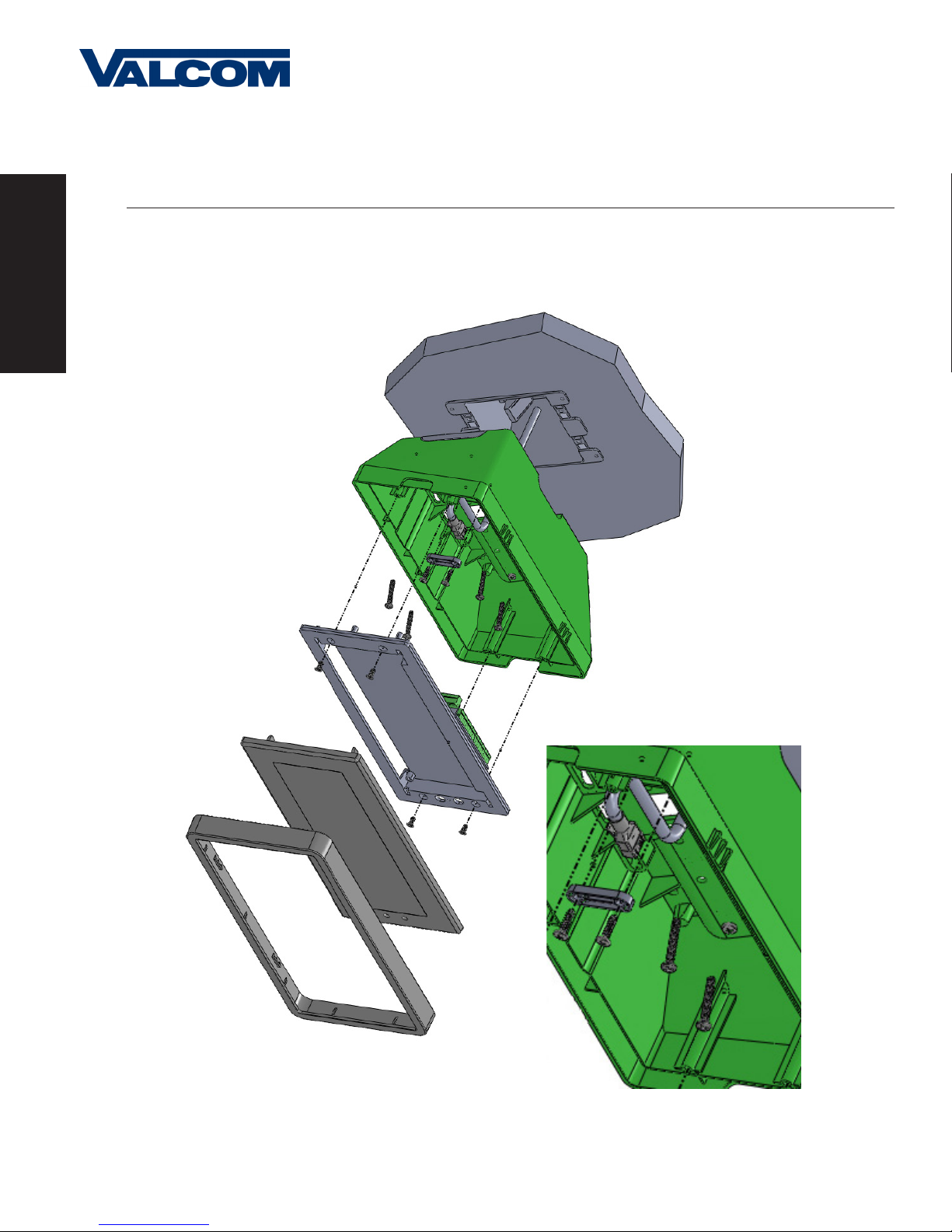
Surface (Wall) Mount Installation (continued)
1. Mount Housing to Wall and/or Gang Box - To mount the housing to the wall, install two (2) wall anchors into the wall (not
supplied in kit) and take two pan head screws no larger than #8 (also not supplied in kit) and drive them into the anchors leaving
an 1/8th inch gap between the head of the screw and the wall. Mount the housing to the wall by lining up the two keyholes in the
back of the housing with the two screws with the 1/8 inch gap and slide the housing onto the heads of the screws. Next, mark the
2 mounting holes at the bottom of the housing on the wall. Remove the housing and install wall anchors at this location. Hang the
housing on the keyholes and install the bottom screws. To mount the housing to the gang box, take the four (4) 6-32 x 1” screws
(supplied in kit) and screw them through the four holes in the center of the inside of the housing and the four holes in the gang
box.
Note: If using a metal gang box, a ground must be provided to the gang box.
2. Feed Wiring Into the Housing - Take the wire coming from the inside of the gang box and feed it through the hole in the
middle of the housing.
3. Plug and Secure Wiring - Loosen the provided wire clamp (comes attached to the inside of the housing) and slip excess wiring
through and tighten the clamp. After securing excess wiring, connect the wiring into the appropriate connector on the back of the
display board. (See the Wiring and Jumper Settings on page 9).
Installation
4. Mount Display Board to Housing - Using the four (4) self tapping, 6-19 x 1/2” flat head screws (supplied in the assembly kit),
take the display board and screw it to the front side of the clock housing (4 screws per clock).
5. Snap on Filter - Take the red filter bezel and snap it on to the front side of the housing.
6. Snap on Frame - Take the gray frame and snap it on to the front side of the housing.
5
Page 6

Valcom, Inc.
5614 Hollins Road
Roanoke, VA 24019
USA
Double Mount Installation
+1 540-563-2000 P.
+1 540-362-9800 F.
www.valcom.com
Installation
u
e
a
q
o
t
i
w
w
y
r
6
Page 7

Valcom, Inc.
5614 Hollins Road
Roanoke, VA 24019
USA
+1 540-563-2000 P.
+1 540-362-9800 F.
www.valcom.com
Double Mount Installation (continued)
*For metal mounting bracket: Use a wall anchor that can support 50 lbs or more with a maximum
screw size of #8
1. Install metal mounting bracket -
First, remove the metal mounting bracket from the inside of the double mount base by
Installation
unscrewing the two
metal mounting bracket to the wall or ceiling in which the clocks are being installed. To mount to the double gang switch box, screw
the four (4) 6-32 x 1” screws (supplied in the assembly kit) through the inner four holes of the metal mounting bracket. Use the outer
four holes to mount to the anchors in the wall (
Note: If using a plastic switch box, a ground wire must be routed through the switch box and into one (1) of
the four (4) metal mounting bracket screws in order to provide ground to the metal mounting bracket. The metal
mounting bracket
wall.
2. Mount clock housings to pole -
where the wiring will be routed (the installer will choose which hole at the end of the pole to use based on how far they want the
clock to sit from the wall). Screw from the inside of the housing into the four holes surrounding the hole in the center of the housing
using the four (4) 8-32 x 7/16” screws (supplied in the assembly kit - 4 screws per clock), securing both housings to the mounting pole.
(2) 6-32 x 1/2” screws located on the underside of the base (save these screws for step #5). Next, screw the
both anchors and screws are not supplied in kit
be secured by both the screws going to the switch box
MUST
Align the hole in the center each housing with one of the three holes on the mounting pole
).
the anchors going into the
AND
Note: End caps from one side of each clock must be removed to mount both clocks to the mounting pole.
Remove one end cap from each clock from the side in which the mounting pole enters the clock.
3. Screw both housings together - Using the two (2) self tapping, 6-19 x 7/16” screws (supplied in the assembly kit), screw both
back sides of the clock housings together (2 screws per clock).
*Instructions continued on next page
7
Page 8

Valcom, Inc.
5614 Hollins Road
Roanoke, VA 24019
USA
+1 540-563-2000 P.
+1 540-362-9800 F.
www.valcom.com
Double Mount Installation (continued)
Installation
4. Feed wiring through base and pole - Take the wiring coming from the switch box and begin to feed it through the center of
the base of the mounting assembly until it emerges from the hole in the center of the clock housing. Make sure there is roughly 1.5’
of wiring coming from the switch box. Perform this task for both clocks.
5. Snap and screw base to metal mounting bracket - Snap the base to the metal mounting bracket by first making contact with
the lip in the upper side of the base and the metal mounting bracket. When the base has been snapped onto the bracket, take
the two (2) 6-32 x 1/2” pan head screws that originally came installed on the base and screw them back into the two holes on the
underside of the base to secure the base to the metal mounting bracket.
6. Connect switch box wires to clock harness - Take the wiring harness supplied with the clock and make all necessary
connections between the wiring harness and the switch box wires using wire nuts. Perform this task for both clocks.
7. Plug and secure wiring - Loosen and slip excess wiring through provided wire clamp (comes attached to each housing) and
tighten the clamp. After securing excess wiring, connect the wiring harness into the appropriate connector on the back of the
display board. Perform this task for both clocks. (See the Wiring and Jumper Settings on page 9).
8. Mount display board to housing - Using the four (4) self tapping, 6-19 x 1/2" flat head screws supplied in the assembly kit,
take the display board and screw it to the front side of the clock housing (4 screws per clock).
9. Snap on filter - Take the red filter bezel and snap it on to the front side of each clock housing.
10. Snap on frame - Take the gray frame and snap it on to the front side of each clock housing.
8
Page 9

Wiring Information
Wiring and Jumper Settings
Valcom, Inc.
5614 Hollins Road
Roanoke, VA 24019
USA
**Jumper Position
+1 540-563-2000 P.
+1 540-362-9800 F.
www.valcom.com
Please note that items within the
dotted lines are applicable only to the
SBL 3200 or 3300 series.
*Contact Rating
0.3A @ 120VAC
Input A
Input B
1 2 3 4
J7 - RS485
JP 6
JP 5
JP 4
JP 3
JP 2
JP 1
1 2 3
AC / DC Com
Dry Contact
Dukane Pulse
Dukane Reset
Common
Common
3.3VDC@20ma
Pin
J3 - Relay Output
1
1
2
4
Output B
Output A
3
J1 - Sync Inputs
2 3
4 5
*Relay 1 N.O.
*Relay 2 N.O.
6 7 8 9
Wiring Information
*Jumpers 4, 5 and 6 must be in the Pin 1 & Pin 2 position.
**Note: Be sure to have a jumper present on Pin 1 & 2 or Pin 2 & 3. Below are the
Jumper Positions and what function each corresponds with.
Note: Jumpers are only read on power up.
J2 - User Inputs
Jumper Position Pin 1 & Pin 2 Pin 2 & Pin 3
JP 4 *See Note Below
JP 5 *See Note Below
JP 6 *See Note Below
JP 4 N/A N/A
JP 5 N/A N/A
JP 6 N/A N/A
JP 1 12 Hour Time 24 Hour Time
JP 2 Bright Dim
JP 3 Time Display Only Alternating Date/Time Display
1
2 3
4 5
6 7 8 9
4
523
120VAC @ 0.1A (WHT )
no Connection
User Input 4
User Input 3
User Input 2
User Input 1
12VDC@ 40ma
Each User Input is
a Contact Closure
Power Settings
1
No Connection
120VAC @ 0.1A (BLK)
No Connection
9
Page 10

Valcom, Inc.
5614 Hollins Road
Roanoke, VA 24019
USA
+1 540-563-2000 P.
+1 540-362-9800 F.
www.valcom.com
Support
Frequently Asked Questions
Will the clock cause interference with any of my other wireless devices?
No, the Valcom Wireless Digital Clock works on 915 - 928 MHz frequency-hopping technology. The clock switches frequencies
automatically when the receiver and transmitter are open, thus interference is avoided.
How long does it take for the clock to receive a signal?
Upon power up, the clock will look for the signal for 30 minutes. The Valcom Wireless Digital Clock will look for the signal every minute
thereafter.
Do the Valcom Wireless Digit al Clocks work together with Valcom’s wireless analog clocks?
Yes, the Valcom Wireless Digital Clocks work integrally with Valcom’s wireless analog clocks.
How many ways can I mount the Valcom Wireless Digital Clock?
The clock can be mounted in either surface or double mount. Please see pages 4 through 8 for more information on mounting
instructions.
Can the Valcom Wireless Digital Clock be used as an independent clock?
No, the Valcom Wireless Digital Clock requires a communication input and must be used with either a Valcom Transceiver or Repeater.
What will happen if the clock is not receiving a signal?
The colon on the display will flash every second.
How can the clock be powered?
The clock is available in 120VAC models.
Support
10
Page 11

Valcom, Inc.
5614 Hollins Road
Roanoke, VA 24019
USA
+1 540-563-2000 P.
+1 540-362-9800 F.
www.valcom.com
Support
Troubleshooting
What happens if the clock doesn’t power up?
Make sure the wiring is correct. If the clock is 120VAC, the power should be on the black and white wires. The middle (green) wire is ground. If
the wiring is correct, take a volt meter and measure the voltage. For 120VAC models, the voltage should read 85 - 135 volts.
What happens if the clock does not receive the signal?
Take the clock within close proximity to the transmitter and power the clock. If the clock does not correct, call Valcom technical support.
I have a location with a marginal signal. What should I do?
Try to install a repeater in a nearby area to the location or install a 120VAC clock.
Support
11
 Loading...