

Page 1

Installation Manual V10.5
Valcom Wired Digital Clock
V-D11025B, V-D11040B, V-2425B-6, and V-D2440B-6
Current as of February 2017
Valcom, Inc.
5614 Hollins Road
Roanoke, VA 24019
USA
P. 540-563-2000
F. 540-362-9800
www.valcom.com
Page 2
Valcom Digital Series 2-Wire and 3-Wire Clocks
Table of Contents
Table of Contents 2
Important Safety Instructions 3
Wall Mount Installation 4 - 10
Flag Mount Installation 11 - 19
Double Mount Installation 20 - 28
Adjustable Jumper Settings 29
Inputs
System Side - 2-Wire Digital Communication 30
Valcom, Inc.
5614 Hollins Road
Roanoke, VA 24019
USA
P. 540-563-2000
F. 540-362-9800
www.valcom.com
- 3-Wire Synchronous (Sync-Wire)
Communication 110VAC 31
Clock Side - Sync-Wire 32-35
Outputs 36
Manual Controls 37-43
Reading the Display 44
Frequently Asked Questions 45
Troubleshooting 46
Warranty 47
Available with V-D110XXB models only
Manuals may change without prior notice
2
Page 3
Valcom, Inc.
5614 Hollins Road
Roanoke, VA 24019
USA
P. 540-563-2000
F. 540-362-9800
www.valcom.com
Important Safety Instructions
VERY IMPORTANT:
KNOW YOUR COMMUNICATION PROTOCOL
The Valcom V-D110XXB Digital clocks are designed to support various 3-wire (sync-wire) communication
protocols. To run each protocol properly, the clock requires the correct wiring format. It is very important
that you only follow the wiring instructions appropriate to your clock’s communication protocol. Using the
wrong wiring format may damage the clock.
DANGER
! !
SHOCK HAZARD
,
• Keep the electricity to this device turned
OFF until the clock installation
is complete.
• Do not expose the clock movement to
water, or install the clock in a location
where it may be exposed to water.
H
|
NOTICE
• Do not install the clock outdoors.
Damage to the clock if placed outdoors
voids the warranty.
• Do not hang objects from the clock or clock
mounting parts. The clocks are not designed
to support the weight of other objects.
• The clock face and housing may be cleaned
with a damp cloth or disinfectant. Test
other cleaning products on a small part of
the clock housing before attempting to use
on the rest of the clock. Avoid bleach and
chemicals known to dissolve plastics.
WARNING
FIRE HAZARD
• Always follow your national and regional
electrical codes or ordinances.
• The AC power circuit for the clock must
be attached to a circuit breaker that can
be reset by the user.
PHYSICAL INJURY HAZARD
• If you are standing on an object while
installing your clock, make sure that the
object can support your weight, and will not
sway or move as you stand on it.
• Take precautions to avoid injury by potential
safety hazards near the point of installation
including (but not limited to) heavy
machinery, sharp objects, hot surfaces, or
exposed cables carrying an electric current.
• Follow all mounting instructions exactly as
stated in this manual. Failure to do so may
result in the device falling off the point of
installation.
• Packaging materials and mounting items
include plastic bags and small pieces, which
pose a suffocation hazard to young children.
3
Page 4
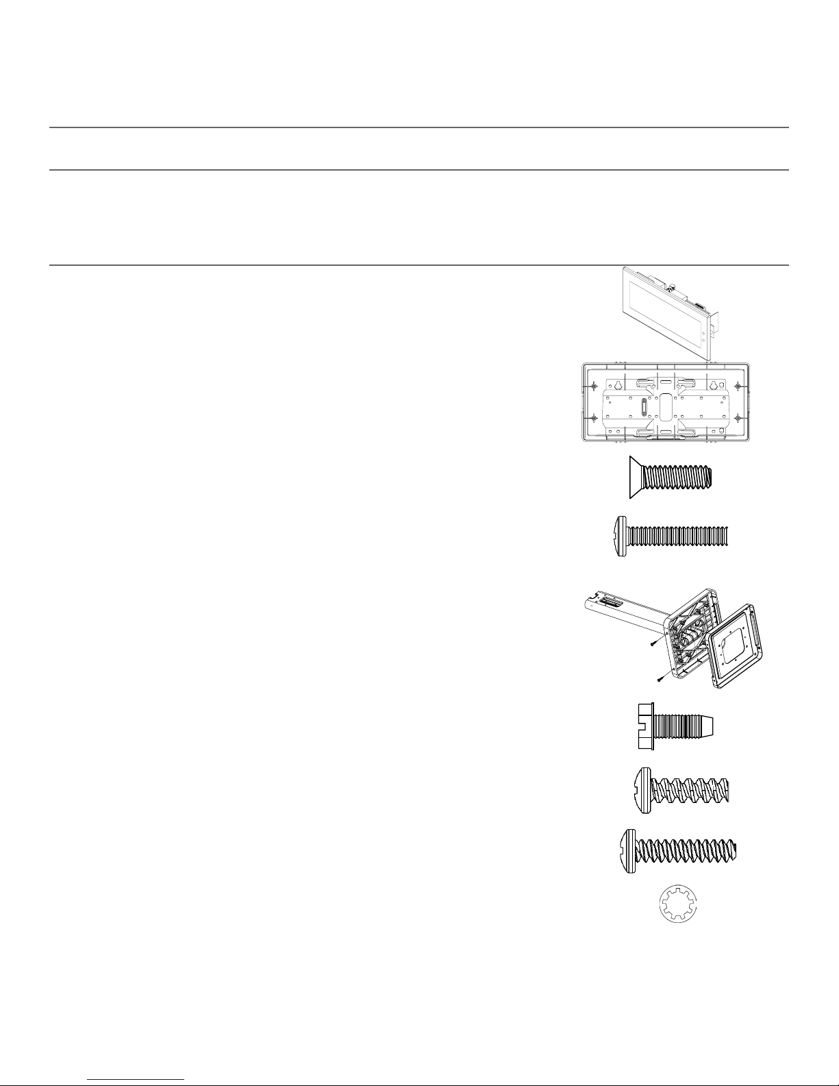
Wall Mount Installation
Included in Package
Valcom, Inc.
5614 Hollins Road
Roanoke, VA 24019
USA
P. 540-563-2000
F. 540-362-9800
www.valcom.com
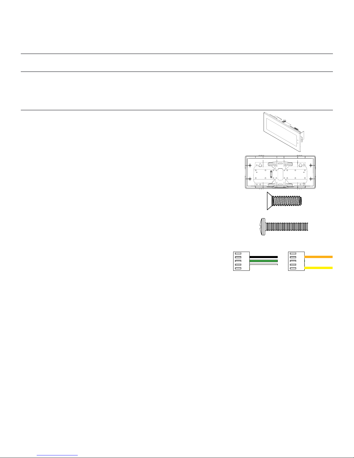
Description
Valcom Digital Clock
Digital Clock Wall Housing
6-19x1/2 screw
6-32x1 screw
Quantity
1
1
4
4
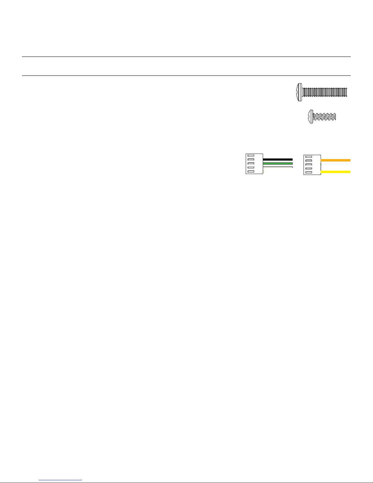
Included in Wiring Kit (D-PK-3-110-S or D-PK-3-24-S)
Power/grounding wires
and connector
1
Picture
110V 24V
or
PLEASE NOTE: A user will also have to provide a Phillips-head screwdriver, a small flat-blade screwdriver, a single gang box, any equipment needed to install
the gang box, and any additional wiring needed to extend the signal, power, or ground cables. You may also need a 1/4 inch drill, 4 #8x1.5 self-tapping
screws, and 4 wall anchors for those screws if you decide not to attach the clock directly to the gang box.
If any of the items listed in the wiring kit are missing, you may contact Valcom and order a
replacement kit.
4
Page 5
Wall Mount Installation
Valcom, Inc.
5614 Hollins Road
Roanoke, VA 24019
USA
P. 540-563-2000
F. 540-362-9800
www.valcom.com
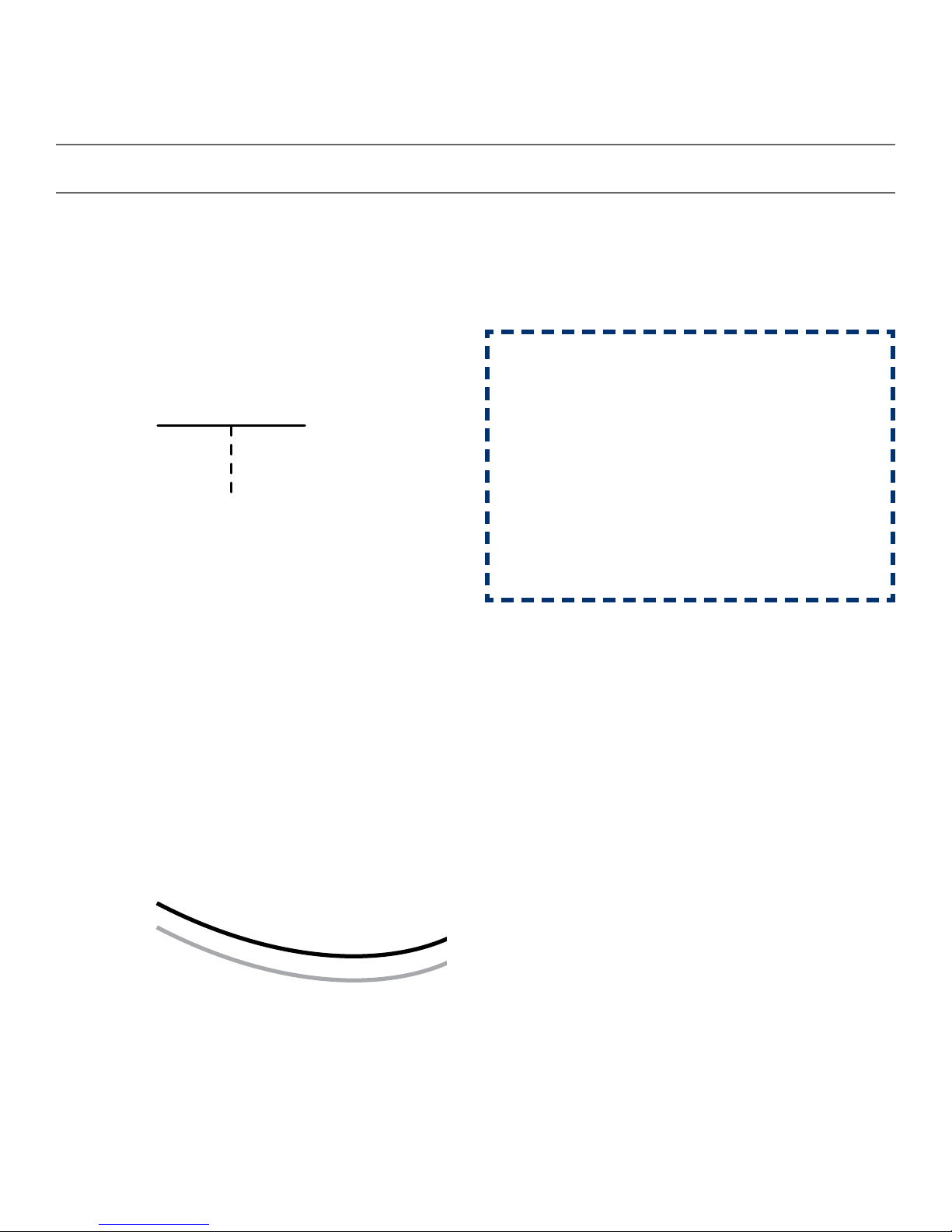
1) If you are installing a new gang box in the wall,
leave at least 4 inches between the top of the gang
box and ceiling. Confirm that the bottom of the
gang box is level with the floor.
If you are using an existing gang box, the top of the
gang box must be a minimum of three inches away
from the ceiling.
Ceiling
1
4” Minimum
2) Run power and communication wiring to the
gang box. See the sections of this manual labeled
“Inputs - System Side” for additional details,
depending on your system.
CHECK YOUR WIRING
The voltage between the white and black wires
should measure 105-126 volts AC in the 110
volt model, or Yellow & orange wires for 21.5-
26.5 volts DC in the 24 volt model.
If you are using the 24 volt model, make sure
that the wiring leading to the clock is from a
Valcom power supply or V-VCU.
2
3) Attach the communication and power wires from
your kit to the communication and power wires
in the gang box. See the sections of this manual
labeled “Communication Wiring Information”for
additional details, depending on your system.
3 4
4) If you do not wish to attach the housing to the
gang box, proceed to step 5A. Otherwise, go to
step 6.
5
Page 6
Wall Mount Installation
Valcom, Inc.
5614 Hollins Road
Roanoke, VA 24019
USA
P. 540-563-2000
F. 540-362-9800
www.valcom.com
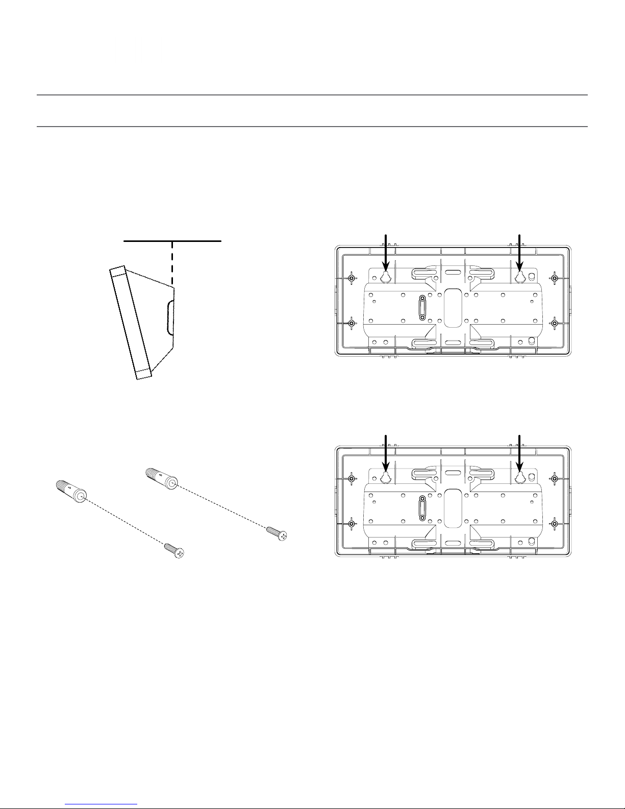
5A) If you do not wish to attach the housing to a
gang box, place the mounting piece on the wall.
Leave at least 4 inches between the top rear edge
of the housing and ceiling. Confirm that the bottom
of the mounting piece is level with the floor.
Ceiling
4” Minimum
5A
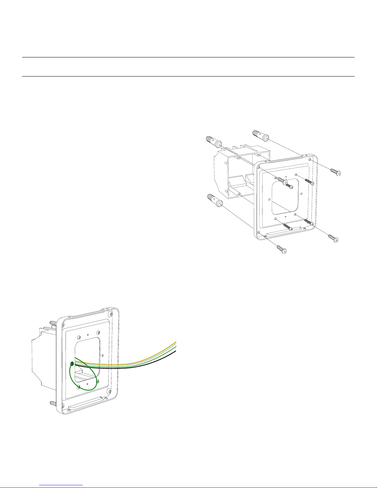
5C) Insert the wall anchors into the two holes, then
place a #8 self-tapping screw into each wall anchor,
leaving at least a 1/8” gap between the top of the
screw and the wall.
5B) Identify the keyholes towards the top of the
back of the clock housing. Use a pencil to trace the
top of each keyhole onto the wall, then use the
1/4 inch drill bit to drill holes at the locations of the
two marks.
5B
5D) Use the keyholes in the back of the housing to
hang the clock onto the screws.
5C
5D
6
Page 7

Wall Mount Installation
Valcom, Inc.
5614 Hollins Road
Roanoke, VA 24019
USA
P. 540-563-2000
F. 540-362-9800
www.valcom.com
5E) Use a pencil to trace the holes beneath each
keyhole onto the wall. Take the clock housing off
the wall, drill holes at the marked locations, and add
another two wall anchors.
5E
5G) Run power and signal wires through the large
hole in the back of the housing. Secure the wires by
passing them through the wire clamp.
5F) Repeat step 5D, then pass another pair of #8
screws through the bottom holes and secure them
in the remaining two wall anchors.
5F
6) Perform step 5F, then attach the housing to the
gang box using the #6-32x1 screws.
5G
6
7
Page 8
Wall Mount Installation
Valcom, Inc.
5614 Hollins Road
Roanoke, VA 24019
USA
P. 540-563-2000
F. 540-362-9800
www.valcom.com
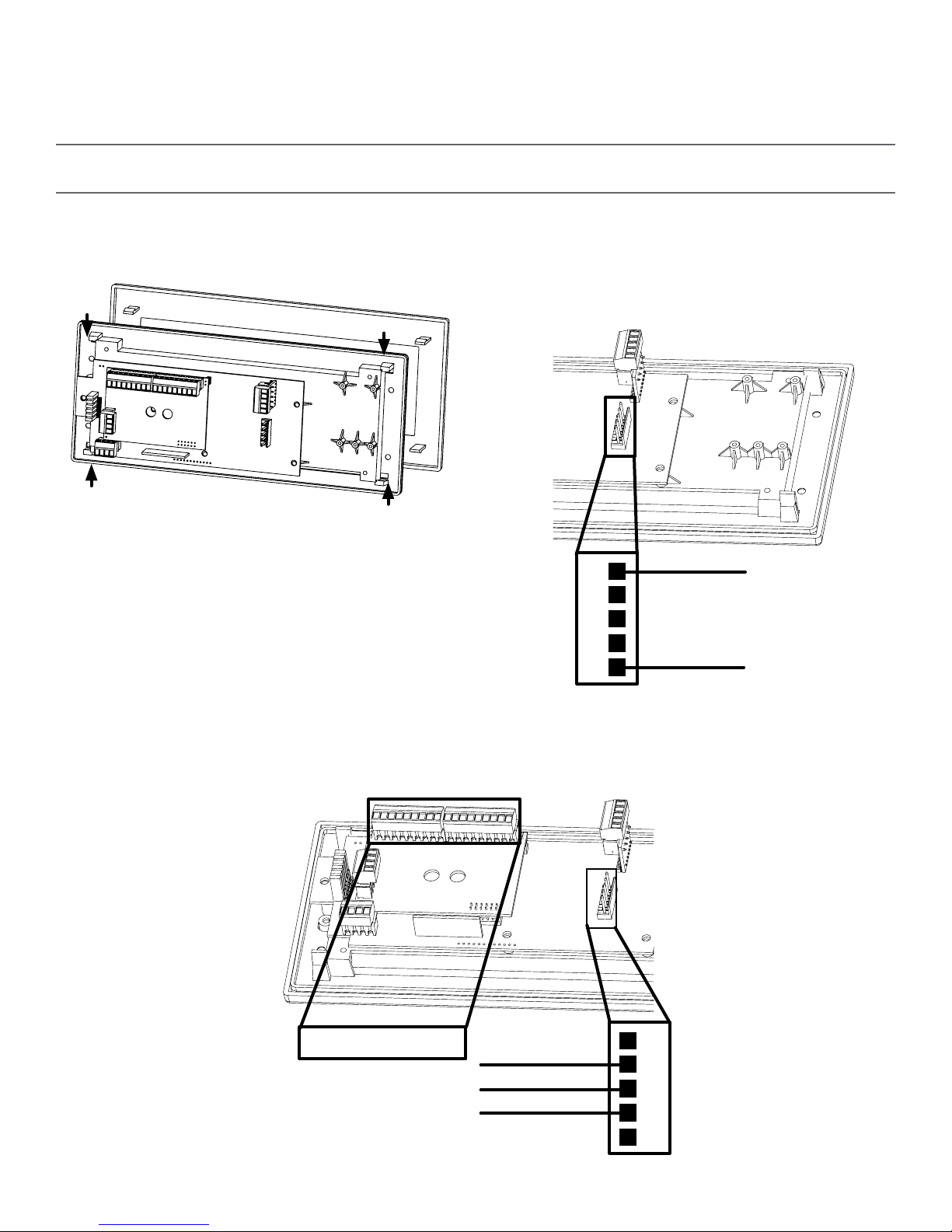
7) Detach the filter from the clock display board by
pressing inward on the red tabs.
7 8A
8A) If you are installing a digital clock that uses a
2-wire digital sync system, attach the wires to the
port as shown below.
1
2
3
4
5
24VDC (Orange)
24VDC (Yellow)
8B) If you are installing a digital clock that uses sync-wire correction, attach the wires to the appropriate
sync-wire ports. Refer to the section, “Inputs - Clock Side - Sync Wire” for instructions regarding each
system.
8B
Sync-Wire Ports
110VAC (Black)
Ground (Green)
110VAC (White)
1
2
3
4
5
8
Page 9
Wall Mount Installation
Valcom, Inc.
5614 Hollins Road
Roanoke, VA 24019
USA
P. 540-563-2000
F. 540-362-9800
www.valcom.com
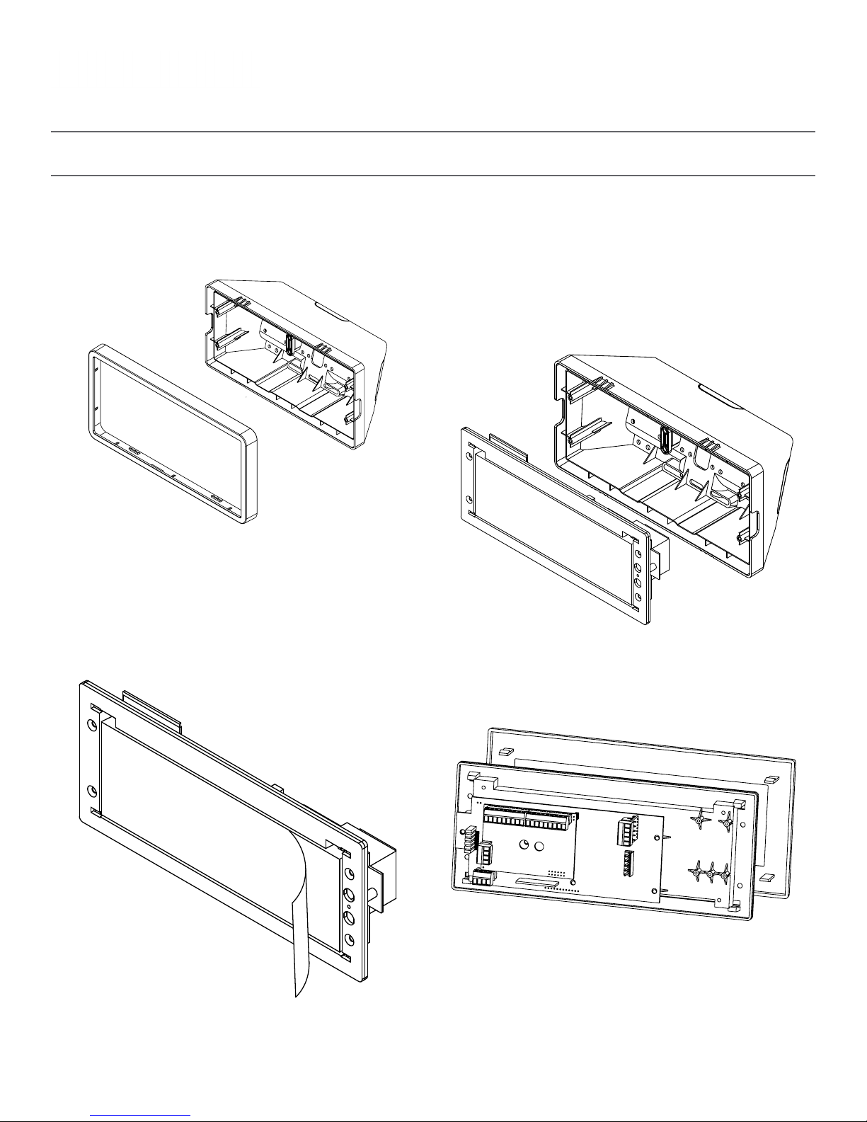
9) Detach the frame from the front of the clock
housing by pulling the bottom and top edges away
from the housing.
9
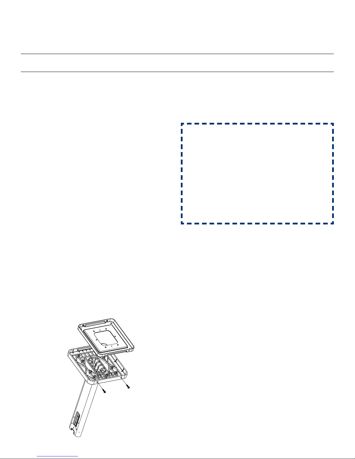
10) Use the 6-19x1/2 screws to attach the display
board to the housing.
NOTE: For 2.5” Digit clocks, the holes for the
screws will be on the left and right inner surfaces of
the housing. For 4.0” Digit Clocks, the holes will be
on the top and bottom surfaces.
10
11) Remove the plastic cover from the display board.
11
12) Place the filter over the display board. You
should hear a snapping noise as the latches drop
into place.
12
9
Page 10
Wall Mount Installation
Valcom, Inc.
5614 Hollins Road
Roanoke, VA 24019
USA
P. 540-563-2000
F. 540-362-9800
www.valcom.com
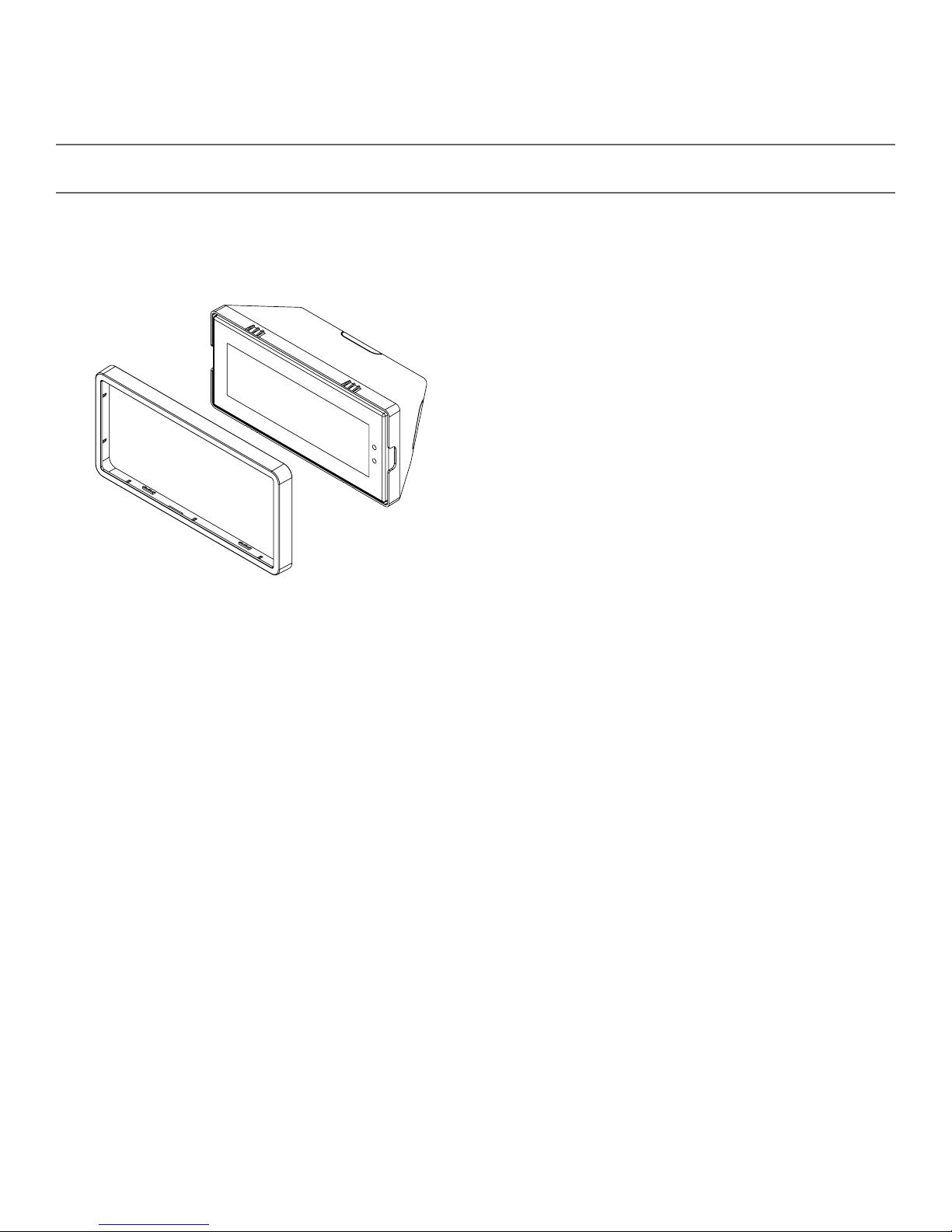
13) Place the housing frame onto the housing. You
should hear a snapping noise as the latches drop
into place.
13 14
14) Power the clock. After testing the LED segments
and presenting some diagnostic information, the
clock will display the time based off if its internal
quartz oscillator. It will correct itself to show
synchronized time as soon as it receives data from a
master clock.
10
Page 11
Flag Mount Installation
Included in Package
Valcom, Inc.
5614 Hollins Road
Roanoke, VA 24019
USA
P. 540-563-2000
F. 540-362-9800
www.valcom.com
Description
Valcom Digital Clock
Digital Clock Wall Housing
6-19x1/2 screw
6-32x1 screw
Included in Pole Kit (V-DMKIT)
Dual-mount pole, including
mounting plate
Quantity
1
1
4
4
1
Picture
#10-32x3/8 green screw
#8-32x7/16 screw
M3.5-1.0x10 screw (black)
Internal-tooth washer
If any of the items listed in the kits are missing, you may contact Valcom and order a replacement kit.
1
8
4
8
Continued on next page
11
Page 12
Flag Mount Installation
Valcom, Inc.
5614 Hollins Road
Roanoke, VA 24019
USA
P. 540-563-2000
F. 540-362-9800
www.valcom.com
#6 -32x1 screw
Adapter tab screws
4
4
Included in Wiring Kit (D-PK-3-110-S or D-PK-3-24-S) - 2 kits included
Power/grounding wires
and connector
PLEASE NOTE: A user will also have to provide a Phillips-head screwdriver, a small flat-blade screwdriver, a single gang box, any equipment needed to install
the gang box, and any additional wiring needed to extend the signal, power, or ground cables. You may also need a 1/4 inch drill, 4 #8x1.5 self-tapping
screws, and 4 wall anchors for those screws if you decide not to attach the clock directly to the gang box.
1
or
If any of the items listed in the wiring kit are missing, you may contact Valcom and order a
replacement kit.
110V
24V
12
Page 13
Flag Mount Installation
Valcom, Inc.
5614 Hollins Road
Roanoke, VA 24019
USA
P. 540-563-2000
F. 540-362-9800
www.valcom.com
1) Install the double gang box in the wall or ceiling.
If you are installing the gang box in the wall, leave
at least eleven inches between the top of the
gang box and the ceiling. If you are installing the
gang box in the ceiling, leave at least eleven inches
between the gang box and the wall. The box should
be installed level and plumb with the wall
and ceiling.
Ceiling
1 2
11” Minimum
2) Run power and communication wiring to the
gang box. See the sections of this manual labeled
“Inputs - System Side” for additional details,
depending on your system.
CHECK YOUR WIRING
The voltage between the white and black wires
should measure 105-126 volts AC in the 110
volt model, or Yellow & orange wires for 21.5-
26.5 volts DC in the 24 volt model.
If you are using the 24 volt model, make sure
that the wiring leading to the clock is from a
Valcom power supply or V-VCU.
3) Detach the mounting plate from the mounting
pole by unscrewing the two screws. Set the screws
and pole aside for later.
3
4) Attach the mounting plate to the gang box using
only two of the four long, silver #6-32x1 screws.
With the mounting plate as a guide, use the pencil
to trace the locations of the four larger holes at the
outer corners.
4
13
Page 14

Valcom, Inc.
5614 Hollins Road
Roanoke, VA 24019
USA
Flag Mount Installation
Steps 5 and 6 only apply to metal mounting poles. If you have an ABS mounting
pole, skip to step 7
5) Remove the mounting pole end cap and the plastic ring from one of the holes.
P. 540-563-2000
F. 540-362-9800
www.valcom.com
5
6) Attach the flag-mount end cap to the pole. Confirm that the covering flap is attached to the side where
the plastic ring was removed.
6
14
Page 15
Flag Mount Installation
Valcom, Inc.
5614 Hollins Road
Roanoke, VA 24019
USA
P. 540-563-2000
F. 540-362-9800
www.valcom.com
7) Remove the mounting plate and drill the four
holes that were just traced. Insert the four wall
anchors into the holes.
7 8
9) Thread any wiring through the mounting plate,
and attach a grounding wire to the mounting plate
using one of the larger centered holes and the
#10-32x3/8 screw.
8) Reattach the mounting plate, this time using all
four long, silver #6-32x1 screws, then insert the
four #8 screws through the mounting plate and into
the anchors.
10) Use a screwdriver to remove one of the end caps.
The selected end cap should match the position of
the orientation of the clock on the mounting pole;
for example, if you wish to attach the clock to the
pole in a ceiling-mount configuration, then the top
end cap should be removed. The end cap and screw
that was used to secure it will not be needed again
during this installation.
9 10
15
Page 16

Flag Mount Installation
Valcom, Inc.
5614 Hollins Road
Roanoke, VA 24019
USA
P. 540-563-2000
F. 540-362-9800
www.valcom.com
11) Detach the frame from the front of the clock
housing by pulling the bottom and top edges away
from the housing.
11 12
13) Thread at least fifteen inches (38.1cm) of
wiring from the gang box through the bottom of
the pole until each wire exits through the hole in
the adapter.
12) Insert the four #8-32x7/16 screws through the
internal-tooth washers, then through the adapter,
and finally into the pole. Use a screwdriver to
tighten the screws so that the adapter does
not move.
14) Detach the filter from the clock display board by
pressing inward on the red tabs.
13
Adapter holeWire Clamp
14
16
Page 17

Flag Mount Installation
Valcom, Inc.
5614 Hollins Road
Roanoke, VA 24019
USA
P. 540-563-2000
F. 540-362-9800
www.valcom.com
15A) If you are installing a digital clock that uses a
2-wire digital sync system, attach the wires to the
port as shown below.
15C) If you are installing a digital clock that uses
sync-wire correction, attach the wires to the
appropriate sync-wire ports. Refer to the section,
“Inputs - Clock Side - Sync Wire” for instructions
regarding each system.
15A 15B
1
2
3
4
5
24VDC (Orange)
24VDC (Yellow)
Sync-Wire Ports
110VAC (Black)
Ground (Green)
110VAC (White)
1
2
3
4
5
16) Use the M3/5-15x12 screws to attach the display board to the housing.
NOTE: For 2.5” Digit clocks, the holes for the screws will be on the left and right inner surfaces of the
housing. For 4.0” Digit Clocks, the holes will be on the top and bottom surfaces.
16
17
Page 18

Flag Mount Installation
Valcom, Inc.
5614 Hollins Road
Roanoke, VA 24019
USA
P. 540-563-2000
F. 540-362-9800
www.valcom.com
17) Use the 6-32x12 screws to attach the display
board to the housing.
NOTE: For 2.5” Digit clocks, the holes for the
screws will be on the left and right inner surfaces of
the housing. For 4.0” Digit Clocks, the holes will be
on the top and bottom surfaces.
17
18) Remove the plastic cover from the display board.
18
19) Place the filter over the display board. You
should hear a snapping noise as the latches drop
into place.
19
20) Place the housing frame onto the housing. You
should hear a snapping noise as the latches drop
into place.
20
18
Page 19

Valcom, Inc.
5614 Hollins Road
Roanoke, VA 24019
USA
Flag Mount Installation
21) Hang the base of the pole on the mounting plate so that the lip is on top of the base, and the holes
for the screws are on the bottom of the base. Attach the wires from the pole to the wires in the gang box,
then use the two black base screws to attach the other side of the base to the mounting plate.
P. 540-563-2000
F. 540-362-9800
www.valcom.com
21
WALL
22) Power the clock. After testing the LED segments and presenting some diagnostic information, the
clock will display the time based off if its internal quartz oscillator. It will correct itself to show synchronized
time as soon as it receives data from a master clock.
CEILING
22
19
Page 20

Double Mount Installation
Included in Package
Valcom, Inc.
5614 Hollins Road
Roanoke, VA 24019
USA
P. 540-563-2000
F. 540-362-9800
www.valcom.com
Description
Valcom Digital Clock
Digital Clock Wall Housing
6-19x1/2 screw
6-32x1 screw
Included in Pole Kit (V-DMKIT)
Dual-mount pole, including
mounting plate
Quantity
1
1
8
8
1
Picture
#10-32x3/8 green screw
#8-32x7/16 screw
M3.5-1.0x10 screw (black)
Internal-tooth washer
If any of the items listed in the kits are missing, you may contact Valcom and order a replacement kit.
1
8
4
8
Continued on next page
20
Page 21

Double Mount Installation
Valcom, Inc.
5614 Hollins Road
Roanoke, VA 24019
USA
P. 540-563-2000
F. 540-362-9800
www.valcom.com
#6 -32x1 screw
Adapter tab screws
4
4
Included in Wiring Kit (D-PK-3-110-S or D-PK-3-24-S) - 2 kits included
Power/grounding wires
and connector
PLEASE NOTE: A user will also have to provide a Phillips-head screwdriver, a small flat-blade screwdriver, a single gang box, any equipment needed to install
the gang box, and any additional wiring needed to extend the signal, power, or ground cables. You may also need a 1/4 inch drill, 4 #8x1.5 self-tapping
screws, and 4 wall anchors for those screws if you decide not to attach the clock directly to the gang box.
1
or
If any of the items listed in the wiring kit are missing, you may contact Valcom and order a
replacement kit.
110V
24V
21
Page 22

Double Mount Installation
Valcom, Inc.
5614 Hollins Road
Roanoke, VA 24019
USA
P. 540-563-2000
F. 540-362-9800
www.valcom.com
1) Install the double gang box in the wall or ceiling.
If you are installing the gang box in the wall, leave
at least eleven inches between the top of the
gang box and the ceiling. If you are installing the
gang box in the ceiling, leave at least eleven inches
between the gang box and the wall. The box should
be installed level and plumb with the wall
and ceiling.
Ceiling
1
11” Minimum
2) Run power and communication wiring to the
gang box. See the sections of this manual labeled
“Inputs - System Side” for additional details,
depending on your system.
CHECK YOUR WIRING
The voltage between the white and black wires
should measure 105-126 volts AC in the 110
volt model, or Yellow & orange wires for 21.5-
26.5 volts DC in the 24 volt model.
If you are using the 24 volt model, make sure
that the wiring leading to the clock is from a
Valcom power supply or V-VCU.
2
3) Detach the mounting plate from the mounting
pole by unscrewing the two screws. Set the screws
and pole aside for later.
3
4) Attach the mounting plate to the gang box using
only two of the four long, silver #6-32x1 screws.
With the mounting plate as a guide, use the pencil
to trace the locations of the four larger holes at the
outer corners.
4
22
Page 23

Double Mount Installation
Valcom, Inc.
5614 Hollins Road
Roanoke, VA 24019
USA
P. 540-563-2000
F. 540-362-9800
www.valcom.com
5) Remove the mounting plate and drill the four
holes that were just traced. Insert the four wall
anchors into the holes.
5 6
7) Thread any wiring through the mounting plate,
and attach a grounding wire to the mounting plate
using one of the larger centered holes and the
#10-32x3/8 screw.
6) Reattach the mounting plate, this time using all
four long, silver #6-32x1 screws, then insert the
four #8 screws through the mounting plate and into
the anchors.
8) Use a screwdriver to remove one of the end caps.
The selected end cap should match the position of
the orientation of the clock on the mounting pole;
for example, if you wish to attach the clock to the
pole in a ceiling-mount configuration, then the top
end cap should be removed. The end cap and screw
that was used to secure it will not be needed again
during this installation.
7 8
23
Page 24

Double Mount Installation
Valcom, Inc.
5614 Hollins Road
Roanoke, VA 24019
USA
P. 540-563-2000
F. 540-362-9800
www.valcom.com
9) Detach the frame from the front of each clock
housing by pulling the bottom and top edges away
from the housing.
9 10
11) Attach adapters to each other using adapter tab
screws, two on each side.
10) Insert the four #8-32x7/16 screws through the
internal-tooth washers, then through each adapter,
and finally into the pole. Use a screwdriver to
tighten the screws so that the adapters do
not move.
12) Thread at least fifteen inches (38.1cm) of
wiring from the gang box through the bottom of
the pole until each wire exits through the hole in
each adapter. Secure the wires by passing them
through the wire clamp.
11
13) Detach the filter from the clock display board by
pressing inward on the red tabs.
13
12
Adapter holeWire Clamp
24
Page 25

Valcom, Inc.
5614 Hollins Road
Roanoke, VA 24019
USA
P. 540-563-2000
F. 540-362-9800
www.valcom.com
Double Mount Installation
13) Attach the signal and power wires from your kit to the wires you threaded through the poles. Consult
the diagrams below for additional help, or see the sections of this manual labeled “3-Wire Synchronous
(Sync-Wire) Communication Wiring Information” or “2-Wire Digital Communication Wiring Information”
for additional details, depending on your system.
Please refer to the wiring guide
3-Wire Sync
To next
clock
A1/B1/C1
13
Gang
Box
Yellow
Orange
A2/B2/C2
Black
White
Yellow
Orange
2-Wire Digital
V-VCU
110VAC
CLOCK 1CLOCK 2
Input A
Input B
Master Clock
18
19
25
Page 26

Double Mount Installation
Valcom, Inc.
5614 Hollins Road
Roanoke, VA 24019
USA
P. 540-563-2000
F. 540-362-9800
www.valcom.com
14A) If you are installing digital clocks that use a
2-wire digital sync system, attach the wires to the
port as shown below.
14C) If you are installing digital clocks that use syncwire correction, attach the wires to the appropriate
sync-wire ports. Refer to the section, “Inputs - Clock
Side - Sync Wire” for instructions regarding each
system.
14A 14B
1
2
3
4
5
15) Use the M3/5-15x12 screws to attach each display board to the housing.
24VDC (Orange)
24VDC (Yellow)
Sync-Wire Ports
110VAC (Black)
Ground (Green)
110VAC (White)
1
2
3
4
5
NOTE: For 2.5” Digit clocks, the holes for the screws will be on the left and right inner surfaces of the
housing. For 4.0” Digit Clocks, the holes will be on the top and bottom surfaces.
15
26
Page 27

Double Mount Installation
Valcom, Inc.
5614 Hollins Road
Roanoke, VA 24019
USA
P. 540-563-2000
F. 540-362-9800
www.valcom.com
16) Use the M3.5-1.5x12 screws to attach a display
board to each housing.
NOTE: For 2.5” Digit clocks, the holes for the
screws will be on the left and right inner surfaces of
the housing. For 4.0” Digit Clocks, the holes will be
on the top and bottom surfaces.
16
17) Remove the plastic cover from each display board.
17
18) Place a filter over each display board. You
should hear a snapping noise as the latches drop
into place.
18
19) Place a housing frame onto each housing. You
should hear a snapping noise as the latches drop
into place.
19
27
Page 28

Valcom, Inc.
5614 Hollins Road
Roanoke, VA 24019
USA
Double Mount Installation
20) Hang the base of the pole on the mounting plate so that the lip is on top of the base, and the holes
for the screws are on the bottom of the base. Attach the wires from the pole to the wires in the gang box,
then use the two black base screws to attach the other side of the base to the mounting plate.
P. 540-563-2000
F. 540-362-9800
www.valcom.com
20
WALL
21) Power the clock. After testing the LED segments and presenting some diagnostic information, the clock
will display the time based off if its internal quartz oscillator. It will correct itself to show synchronized time
as soon as it receives data from a master clock.
CEILING
21
28
Page 29

Valcom, Inc.
5614 Hollins Road
Roanoke, VA 24019
USA
P. 540-563-2000
F. 540-362-9800
www.valcom.com
Adjustable Jumper Settings
Every version of the digital clock contains a set of jumpers which can be moved to change a particular
setting. The functions and positions of each jumper are described below:
Left Position Right Position
Pins 1 & 2 Pins 2 & 3
Jumper 1 12 Hour Time
(Default)
Jumper 2 Display High
Brightness
(Default)
Jumper 3 Display Time Only
(Default)
Jumper 4 DO NOT TOUCH
(Default)
Jumper 5 DO NOT TOUCH
(Default)
Jumper 6 Clock accepts
sync-wire inputs
(Default)
24 Hour Time
Display Low
Brightness
Alternate display
between Time
and Date
DO NOT TOUCH
DO NOT TOUCH
DO NOT USE
1
2
3
4
5
6
To manually enable or disable the first three jumpers, refer to the section of this manual labeled “Manual
Controls” and refer to Setting 15.
29
Page 30

Inputs - System-Side - 2-Wire Digital
Valcom Master Clock
18 19
Data In
Valcom, Inc.
5614 Hollins Road
Roanoke, VA 24019
USA
P. 540-563-2000
F. 540-362-9800
www.valcom.com
V-C6124P
+-+-+- +-+-+-
*V-C6124P and the V-CCU are
ordered as a V-VCU.
24 VDC IN24 volt outputs
V-CCU
2 Wire Digital
Output to Clocks
White
Black
V- A 2412 or V-A2416
V-A2412B or V-A2416B
Orange
Yellow
V-D2425B-6 or V-D2440B-6
White
Black
V- A 2412 or V-A2416
V-A2412B or V-A2416B
30
Page 31

Valcom, Inc.
5614 Hollins Road
Roanoke, VA 24019
USA
Inputs - System-Side - Sync-Wire 110VAC (V-D110XXB Only)
Valcom Master Clock
P. 540-563-2000
F. 540-362-9800
www.valcom.com
10 Amp Contact Rating
Clock Circuit
272426
Neutral
Black
White
115 VAC
or
23
Power
Reset
Neutral
Power
Reset
Ground
27 26 25 24 23 22
or*
27 26 25 24 23 22
White
Black
Yellow
Green
Clock Circuit 1
* ”or” means one pair of ports or
the other. You cannot, for instance,
Clock Circuit 2
use port 23 for reset and 27 for
power, nor can you use 26 for reset
and 24 for power. You must use
the pair 24 AND 23 or the pair
26 AND 27
V- A11012 o r V- A11016
V-A11012B or V-A11016B
Neutral
Reset
Power
Neutral
Ground
Neutral
Power
Reset
Ground
J1-1
J1-2
Black
White
Green
White
Black
Yellow
Green
Correction
Power
V- D11025 B or V- D1104 0 B
Red & Blue Wires are NOT provided by Valcom
V- A11012 o r V- A11016
V-A11012B or V-A11016B
31
Page 32

Inputs - Clock-Side - Sync-Wire (V-D110XXB Only)
Inputs for sync-wire protocols are located on the
upper-port block on the back of the clock. For this
manual, the ports in each block are listed as 1-9,
starting with port 1 on the left, and ending with
port 9 on the right.
1
Valcom, Inc.
Valcom, Inc.
5614 Hollins Road
5614 Hollins Road
Roanoke, VA 24019
Roanoke, VA 24019
USA
USA
9
1
P. 540-563-2000
P. 540-563-2000
F. 540-362-9800
F. 540-362-9800
www.valcom.com
www.valcom.com
9
There are two port blocks. In this manual, the block
on the left will be called J1, while the block on the
right will be called J2. Refer to the diagram
for details.
The diagrams on the following pages indicate how
wires should be run between the various ports on
the clock and the network to allow for the use of
Sync-wire protocols.
Before a clock can use these protocols, it must
be configured to accept the intended protocol as
its input through the front buttons. Refer to the
sections “Manual Controls”
59 Minute Correction
J1-
1 2 3 4 5 6
9
8
7
J1
J1-
12345
J2
6
7 8
9
J2-
1 2
Neutral
Reset
110VAC I n ter fac e
Description:
59 Minute Correction - 110VAC 60 Hz is used to run the clock normally. Applying an eight (8) second
reset signal from 57 minutes and 54 seconds will cause an hourly correction. Applying a fourteen (14)
second reset signal from 5:57:54 will cause a daily correction.
Relay
N.O.
COM
Dry Contact Closure
32
32
Page 33

Inputs - Clock-Side - Sync-Wire (V-D110XXB Only)
58 Minute Correction
Valcom, Inc.
5614 Hollins Road
Roanoke, VA 24019
USA
P. 540-563-2000
F. 540-362-9800
www.valcom.com
J1-
Neutral
Reset
1 2 3 4 5 6
9
8
7
Relay
N.O.
COM
J1-
12345
6
7 8
9
J2-
1 2
110VAC I n ter fac e
Dry Contact Closure
Description:
110VAC 60 Hz is used to run the clock normally. Refer to the table below for the four variations on 58
minute correction:
58th minute (1) - The hourly correction for 55 seconds every hour from XX:58:05 to XX:59:00. The daily
correction (5 a.m. & 5 p.m.) is ten correction cycles sent to the relay (each for 95 seconds) beginning at
5:05:00, 5:07:00, 5:09:00, 5:11:00, 5:13:00, 5:15:00, 5:17:00, 5:19:00, 5:21:00, and 5:23:00.
58th minute (2) - The hourly correction for 60 seconds every hour from XX:58:00 to XX:59:00. The daily
correction (5 a.m. & 5 p.m.) is twelve correction cycles sent to the relay (each for 65 seconds on and 25
seconds off) beginning at 5:05:00 to 5:22:35.
58th minute (3) - The hourly correction for 60 seconds every hour from XX:58:00 to XX:59:00. The daily
correction (5 a.m. & 5 p.m.) is twelve correction cycles sent to the relay (each for one minute on and two
minutes off) beginning at 5:06:00.
58th minute (4) - The hourly correction for 55 seconds every hour from xx:58:05 to XX:59:00. The daily
correction (5 a.m. & 5 p.m.) is 12 correction cycles for 55 seconds. The timings will be 05:03:05, 05:07:05,
05:11:05, 05:15:05, 05:19:05, 05:23:05, 05:27:05, 05:31:05, 05:35:05, 05:39:05, 05:43:05 and 05:47:05.
33
Page 34

Inputs - Clock-Side - Sync-Wire (V-D110XXB Only)
National Time/Rauland
Valcom, Inc.
5614 Hollins Road
Roanoke, VA 24019
USA
P. 540-563-2000
F. 540-362-9800
www.valcom.com
J1-
Neutral
Reset
1 2 3 4 5 6
9
8
7
Relay
N.O.
COM
J1-
12345
6
7 8
9
J2-
1 2
110VAC I n ter fac e
Dry Contact Closure
Description:
National Time/Rauland - 110VAC 60 Hz is used to run the clock normally. Applying a 25 second reset
signal when minutes equal 00 and seconds equal 00 will cause an hourly correction. Applying a 24
minute reset signal when hours equal 06 or 18 and minutes equal 00 and second equals 25 will cause
a daily correction.
Rauland Digital
J1-
1 2
3
4 5
678 9
Description:
Rauland Digital - Applying a half second pulse for every minute to the Dig. Line will bring the clock to
the correct time. The clock will jump to the correct time at the end of the correction pulse.
Note: For better synchronization, it is recommended to work on a 60 Hz time base.
5V
Digital
34
Page 35

Inputs - Clock-Side - Sync-Wire (V-D110XXB Only)
Dukane
Valcom, Inc.
5614 Hollins Road
Roanoke, VA 24019
USA
P. 540-563-2000
F. 540-362-9800
www.valcom.com
J1-
Reset
Minute Pulse
Ground
12345
6
7 8
9
J2-
1 2
Description:
Dukane - Applying a 4-10 millisecond pulse on the minute line will increment the clock in one minute.
Applying a 12-50 millisecond pulse on the reset line will bring the clock back to 12:00 a.m.
Midnight Reset or Once a Day Pulse
J1-
1 2 3 4 5 6
9
8
7
J1-
12345
6
7 8
9
J2-
1 2
Neutral
Reset
Relay
N.O.
COM
110VAC I n ter fac e
Dry Contact Closure
Description:
Midnight Reset or Once a Day Pulse - Applying a pulse for more than two (2) seconds will bring the
clock to the correct time.
35
Page 36

Valcom, Inc.
5614 Hollins Road
Roanoke, VA 24019
USA
P. 540-563-2000
F. 540-362-9800
www.valcom.com
Outputs (V-D110XXB Only)
2-Wire Digital - Master Mode
During a loss of communication with the Master Clock, the V-D110XXB digital clock can act as a
temporary, backup master clock for other clocks in the system. The port block on the bottom left side of
the circuit board will be called J7. Refer to the diagram for details. For J7, the ports in the block are listed as
1-4, starting with port 1 on the left and port 4 on the right.
Brown
Purple
J7-4 J7-3
V- CCU
1
4
J7
Output Relays
(IMPORTANT: Detach clock from power source before installing new circuitry. DO NOT add new circuitry
while the clock is operating)
The port block on bottom left will be called J3. Refer to the diagram for details. For J3, the ports in the
block are listed as 1-4, starting with port 1 on the bottom and port 4 on the top.
J3
or
1 2
Green
White
4
J3
Power
Reset
Intercom, paging system,
or other device
1
36
Page 37

Valcom, Inc.
5614 Hollins Road
Roanoke, VA 24019
USA
P. 540-563-2000
F. 540-362-9800
www.valcom.com
Manual Controls (V-D110XXB Only)
The purpose of this section is to get a new digital clock up and running using the manual controls on the
front of the digital clock.
Although we always recommend that the Digital Clock receive time data from an accurate time
source, if there is a need for the digital clock to act as a standalone device, the Digital Clock’s internal realtime clock can be set manually. This can be done by pressing the top button to advance the hour, and the
bottom button to advance the minute.
Top Button (Hour)
Bottom Button (Minute)
For all other settings, press and release both buttons simultaneously. To return the LED display to showing
the time, repeatedly press the top button until all of the setting codes have been cycled through. The last
code should be 41--99.
The numbers shown on the left are examples. Going down the list and entering every one
of the examples exactly as shown will cause the clock to malfunction or use incorrect data.
Program your clock setting based off of the instructions in the description on the right.
1--10
2--11
3--28
Setting 1 - Set Year
Use the bottom button to scroll from 00 through 99. This permits the user to select
a year from 2000 to 2099.
Setting 2 - Set Month
Use the bottom button to scroll from 01 through 12. This permits the user to select
a month from January (01) to December (12).
Setting 3 - Set Day of the Month
Use the bottom button to scroll from 01 through 31. This permits the user to select
a day from the 1st of the month to the 31st of the month.
Setting 4 - 12/24 Hour Mode
4--24
Press the bottom button to switch between 12 and 24.
12 causes the master clock to display time in 12 Hour mode.
24 causes the master clock to display time in 24 Hour mode.
37
Page 38

Valcom, Inc.
5614 Hollins Road
Roanoke, VA 24019
USA
P. 540-563-2000
F. 540-362-9800
www.valcom.com
Manual Controls (V-D110XXB Only)
The numbers shown on the left are examples. Going down the list and entering every one
of the examples exactly as shown will cause the clock to malfunction or use incorrect data.
Program your clock setting based off of the instructions in the description on the right.
Setting 5 - Daylight Saving Time
5-- d
Press the bottom button to switch between “d’ or “E”
“d” disables Daylight Saving Time
“E” enables Daylight Saving Time
NOTE: Daylight Savings Time set through this method begins on the second
Sunday of March at 2:00 AM, and ends on the first Sunday of November at
2:00 AM.
6-- d
7-- E
8--02
Setting 6 - Alternate Date and Time
Press the bottom button to switch between “d’ or “E”
“d” disables Alternating Time and Date
“E” enables Alternating Time and Date
NOTE: Alternating Time and Date set through this method displays the time for
seven seconds, then displays the date for three seconds, then repeats.
Setting 7 - Date Format
Allows the user to chose the Date format used when the clock is set to display
alternating Date/Time. Press the bottom button to switch between “A” or “E”
“A” Stands for American Style - Month:Day:Year
“E” Stands for European Style - Day:Month:Year
On a 4-digit clock, only the day and month will be displayed.
Setting 8 - Display Brightness
Allows the user to choose the brightness level for the clock’s main display.
Press the bottom button to cycle between values 00, 01, and 02. This values
correspond to Low, Medium, and High (Default)
38
Page 39

Valcom, Inc.
5614 Hollins Road
Roanoke, VA 24019
USA
P. 540-563-2000
F. 540-362-9800
www.valcom.com
Manual Controls (V-D110XXB Only)
The numbers shown on the left are examples. Going down the list and entering every one of
the examples exactly as shown will cause the master clock to malfunction or use incorrect data.
Program your clock setting based off of the instructions in the description on the right.
Setting 9 - Clock I.D. Number
9-- 1
10- 02
Press the bottom button to advance the ID number of the clock. This accepts
the ID numbers 1 through 999.
The ID Number is used for displaying text messages like 911, bELL, and FirE.
Consult the Master Clock manual for more information.
Setting 10 - Zone Number
Press the bottom button to advance the ID number of the clock. This accepts
the Zone Numbers 01 through 99.
The Zone Number is used for displaying text messages like 911, bELL, and FirE.
Consult the Master Clock manual for more information.
Setting 11 - Do not modify.
11 --01
If the value is changed by accident, press the bottom button until this setting
13-- E
Do not modify this setting.
displays option 00.
Setting 13 - Enable Loss of Communication Alert
Press the bottom button to switch between “d’ or “E”
“d” disables Loss of Communication Alert
“E” enables Loss of Communication Alert
When Loss of Communication Alert is enabled, the colons on the display will
blink if the digital clock fails to synchronize with the master clock within a set
amount of time. This amount of time is set through Setting 14.
39
Page 40

Valcom, Inc.
5614 Hollins Road
Roanoke, VA 24019
USA
P. 540-563-2000
F. 540-362-9800
www.valcom.com
Manual Controls (V-D110XXB Only)
The numbers shown on the left are examples. Going down the list and entering every one
of the examples exactly as shown will cause the clock to malfunction or use incorrect data.
Program your clock setting based off of the instructions in the description on the right.
Setting 14 - Loss of Communication Alert Additional Configuration
14--06
Allows the user to determine how much time should pass without a
synchronization signal from the master clock before the Loss of Communication
Alert is activated. Press the bottom button to switch between the numerical
options below:
01 - Activates after 5 minutes 05 - Activates after 45 minutes 09 - Activates after 180 minutes
02 - Activates after 10 minutes 06 - Activates after 60 minutes 10 - Activates after 240 minutes
03 - Activates after 15 minutes 07 - Activates after 90 minutes Note: Alert activates after signal
04 - Activates after 30 minutes 08 - Activates after 120 minutes
loss for the time limit specified
15-- d
Setting 15 - Enable Circuit Board Jumpers
Press the bottom button to switch between “d’ or “E”
“d” disables the jumpers
“E” enables the jumpers
NOTE: Enabling the jumpers overrides Settings 4, 6, and 8. Refer to the section
of this manual labeled “Adjustable Jumper Settings” for information on the
function of each jumper.
40
Page 41

Valcom, Inc.
5614 Hollins Road
Roanoke, VA 24019
USA
P. 540-563-2000
F. 540-362-9800
www.valcom.com
Manual Controls (V-D110XXB Only)
The numbers shown on the left are examples. Going down the list and entering every one
of the examples exactly as shown will cause the clock to malfunction or use incorrect data.
Program your clock setting based off of the instructions in the description on the right.
Setting 20 - Set the Programmable Relay 1
20-- 7
1) 58th Minute (1) - The clock performs an hourly correction that takes 55 seconds and occurs between
XX:58:05 and XX:59:00 of every hour. It also performs two daily corrections: one at 5:00AM and another
at 5:00PM. Each daily correction is ten relay cycles, each cycle is 95 seconds long, and the cycles begin at
5:05AM/PM, 5:07, 5:09, 5:11, 5:13, 5:15, 5:17, 5:19, 5:21, and 5:23 respectively.
2) 58th Minute (2) - The clock performs an hourly correction that takes 60 seconds and occurs between
XX:58:00 and XX:59:00. It also performs two daily corrections: one at 5:00AM and one at 5:00PM. Each
daily correction is made of twelve relay cycles, and each cycle consists of 65 seconds on and 25 seconds
off
Press the bottom button to scroll from 1 to 9 or d. These numbers correspond
to different protocols, specifically:
3) 58th Minute (3) - The clock performs an hourly correction that takes 60 seconds and occurs between
XX:58:00 and XX:59:00. It also performs two daily corrections: one at 5:00AM and one at 5:00PM. Each
daily correction is made of twelve relay cycles, and each cycle consists of 60 seconds on and 120 seconds
off.
4) 58th Minute (4) - The clock performs an hourly correction that takes 55 seconds and occurs between
XX:59:05 and XX:59:00. It also performs two daily corrections: one at 5:00AM and one at 5:00PM. Each
daily correction is made of twelve relay cycles, each cycle is 55 seconds long, and the cycles begin at
5:03:05AM/PM, 5:07:05, 5:11:05, 5:15:05, 5:19:05, 5:23:05, 5:27:05, 5:31:05, 5:35:05, 5:39:05, 5:43:05,
and 5:47:05 respectively.
5) 59th Minute - The clock performs an hourly correction that takes 8 seconds and occurs between
XX:57:54 and XX:58:02. It also performs two daily corrections: one at 5:00AM and one at 5:00PM. Each
daily correction is a single 14 second pulse which lasts from 5:57:54 to 5:58:08.
6) National time & Rauland (1) - The clock performs an hourly correction that takes 25 seconds and
occurs between XX:00:00 and XX:00:25. It also performs two daily corrections: one at 6:00AM and one at
6:00PM. Each daily correction is made of twenty four relay cycles consisting of 25 seconds on, followed by
35 seconds off.
7) National Time & Rauland (2) - The clock performs an hourly correction that takes 25 seconds
and occurs between XX:00:00 and XX:00:25. It also performs two daily corrections at 6:00:25AM and
6:00:25PM. Each daily correction is a single 24 minute pulse which lasts from 6:00:25AM/PM to 6:24:25.
8) Rauland Digital - The clock will reset the secondary clock to 12:00:00AM, then advance the time on
the secondary clock by one minute for every 0.5 seconds that the Digital line is shorted to ground.
9) Once a Day Pulse - The clock relay will close at a specific time and for an amount of time decided by
the clock circuit settings (Settings 21-24 for circuit 1, or 26-29 for circuit 2).
10) Disable Relay - The relay is disabled. This is the default value for this function.
41
Page 42

Valcom, Inc.
5614 Hollins Road
Roanoke, VA 24019
USA
P. 540-563-2000
F. 540-362-9800
www.valcom.com
Manual Controls (V-D110XXB Only)
The numbers shown on the left are examples. Going down the list and entering every one
of the examples exactly as shown will cause the clock to malfunction or use incorrect data.
Program your clock setting based off of the instructions in the description on the right.
Setting 21 - Once a Day Pulse Output - Set Hour
21 --14
22--00
23--30
This setting only appears if “8” was selected under Setting 20. Press the bottom
button to scroll from 00 to 23. For example, a value of 13 is the same as 1:00PM.
Set to 0 by default.
Setting 22 - Once a Day Pulse Output - Set Minutes
This setting only appears if “8” was selected under Setting 20. Press the bottom
button to scroll from 00 to 59. Set to 0 by default.
Setting 23 - Once a Day Pulse Output - Set Seconds
This setting only appears if “8” was selected under Setting 20. Press the bottom
button to scroll from 00 to 59. Set to 0 by default.
24--05
30- 1
31 --14
32--00
Setting 24 - Once a Day Pulse Output - Set Pulse Duration
This setting only appears if “8” was selected under Setting 20. Press the bottom
button to scroll from 00 to 99. For example, a value of 98 will set a pulse
duration of 1 minute and 38 seconds. Set to 3 by default.
Setting 30 - Set Sync Wire Time Input Type
Allows the user to configure the sync wire type used as an Input.
Press the bottom button to scroll from 1 to 9 or d. These numbers correspond to
the different protocols listed below. Set to 8 by default.
d - Disable Auxiliary Input 01 - 58 Minute Correction (1) 02 - 58 Minute Correction (2) 09 - Once a Day Pulse
03 - 58 Minute Correction (3) 04 - 58 Minute Correction (4) 05 - 59 Minute Correction
06 - National Time/Rauland 07 - Dukane Digital 08 - Rauland Digital
Setting 31 - Once a Day Pulse Input - Clock #2 Circuit - Set Hour
This setting only appears if “8” was selected under Setting 20. Press the bottom
button to scroll from 00 to 23. For example, a value of 13 is the same as 1:00PM.
Set to 0 by default.
Setting 32 - Once a Day Pulse Input - Clock #2 Circuit - Set Minutes
This setting only appears if “8” was selected under Setting 20. Press the bottom
button to scroll from 00 to 59. Set to 0 by default.
Setting 33 - Once a Day Pulse Input - Clock #2 Circuit - Set Seconds
33--30
This setting only appears if “8” was selected under Setting 20. Press the bottom
button to scroll from 00 to 59. Set to 0 by default.
42
Page 43

Valcom, Inc.
5614 Hollins Road
Roanoke, VA 24019
USA
P. 540-563-2000
F. 540-362-9800
www.valcom.com
Manual Controls (V-D110XXB Only)
The numbers shown on the left are examples. Going down the list and entering every one
of the examples exactly as shown will cause the clock to malfunction or use incorrect data.
Program your clock setting based off of the instructions in the description on the right.
The settings below only apply to Valcom analog clocks using wired communication protocols such as
2-Wire Digital. The digital clock cannot send these commands to Wireless, IP or Wi-Fi clocks.
Setting 40 - Command Analog Clock to Perform Diagnostic
40-- d
Allows the user to send a command to all analog clocks receiving data from
this digital clock. The available commands are the diagnostic tests listed in the
table below:
01 - Diagnostic 1 -
Protocol Verification
02 - Diagnostic 2 Comprehensive Test
Details on the function of each diagnostic test can be found in the analog
clock manual.
Setting 41 - Diagnostic Results Display Duration
41 - 60
Pressing the top button after Setting 41 will cause the clock to return to the normal time display.
This setting determines how long the results of a diagnostic test will remain
on the face of an analog clock. Due to the nature of the tests, this time period
only applies if values 01 or 02 were selected for Setting 40.
Press the bottom button to scroll from 00 to 99. For example, a value of 98 will
set a display duration of 1 minute and 38 seconds.
03 - Diagnostic 3 - Resets clock to
Manufacturing Default and sets
all hands to 12
04 - Diagnostic 4 - Full
Mechanical and Electrical Test.
Press button on analog to start.
d - Does not send a command
05 - Diagnostic 4 - Full
Mechanical and Electrical Test.
Begins automatically.
09 - Override diagnostic tests and
return analog clocks to showing
master clock time.
43
Page 44

Valcom, Inc.
5614 Hollins Road
Roanoke, VA 24019
USA
P. 540-563-2000
F. 540-362-9800
www.valcom.com
Reading the Display
The digital clock is designed to display time in either a 12-hour or 24-hour format. When the display is set
to the 12-hour format, a circular light will appear in the top left corner of the display to indicate PM, or
disappear to indicate AM. When the display is set to the 24 hour format, the full 24-hour time will appear
on the display; no other lights should appear.
Some examples:
5:30 AM (12-hour format)
5:30 PM (12-hour format)
5:30 AM (24-hour format)
5:30 PM (24-hour format)
The factory default setting for all digital clocks is the 12-hour format. If you wish to set the clock to display
time in a 24-hour format, see the section labeled “Jumper Settings”, included earlier in this manual.
44
Page 45

Valcom, Inc.
5614 Hollins Road
Roanoke, VA 24019
USA
P. 540-563-2000
F. 540-362-9800
www.valcom.com
Frequently Asked Questions
Can this digital clock be used as a standalone clock?
The Valcom Digital V-D110XXB can be used as a standalone clock, but it will not keep synchronized time
in this configuration. Instead, it will rely on an internal quartz oscillator for keeping the time. The clock will
drift by a few seconds each year while in this mode, and will need to be readjusted manually.
How can I use this digital clock with Rauland, Dukane and other systems?
V-D110XXB clocks can be added directly to several sync wire systems. Refer to the Inputs section of this
manual for instructions on how to connect the clock to each system type.
V-D24XXB-6 clocks can obtain time from these systems through a master clock working as a translator.
Data from the other system would be sent to the master clock, and then the master clock would send the
data to the digital clocks through 2-wire or wireless communication protocols.
What happens to the digital clock if a power failure occurs?
If a power failure occurs, the display will shut off but the clock will continue to keep time with its internal
quartz oscillator. This oscillator will continue to run on a tiny battery backup for about ten years. In this
mode, it may drift from synchronized time by a few seconds for each year that the clock is without power.
Once power is restored to the clock, the display will turn on and display the time on the quartz oscillator. It
will correct this to accurate, synchronized time once a signal from a master clock is received.
What happens to the digital clock if contact with the time data source is lost?
The digital clock will rely on an internal quartz oscillator for keeping the time until time data is received.
The clock will drift by a few seconds each year while in this mode, and will need to be readjusted manually.
The V-D110XXB digital clock is able to act as a master clock. If the communication input is lost to the
V-D110XXB, and the V-D110XXB is acting as a master, then the clock will send synchronization data to any
clocks down the line that are connected. This data will be based off of the V-D110XXB’s quartz oscillator,
so while the clocks will be synchronized to each other, they may not be showing accurate time.
How can I display “BELL” and “FirE” on the clock?
“FirE” and “BELL” are signals sent by the appropriate master clock. Refer to the master clock manual
for instructions.
For 24V clocks, what happens if voltage on the power line drops from 24V to lower voltage?
The clock will still function, and will maintain the same level of brightness. However, the current
consumption will increase proportionally to the decrease in voltage.
45
Page 46

Valcom, Inc.
5614 Hollins Road
Roanoke, VA 24019
USA
P. 540-563-2000
F. 540-362-9800
www.valcom.com
Troubleshooting
The clock is not running. What do I do?
1. Measure the input voltage to the clock. The voltage should measure 85-135 volts in the
120VAC model or 240VAC model or 10-28 volts in the 2.5”/24VDC model and 16-28 volt in
the 4.0”/24VDC model.
2. Make sure the ground wire is not touching other wires.
NOTE: If you fail to follow instruction 2 the fuses can be blown.
The clock is not receiving an input signal. What do I do?
1. For V-D110XXB, Make sure that JP6 is in the proper position. Refer to “Adjustable Jumper
Settings“ for
details and diagrams.
2. For V-D24XXB-6, Make sure that the polarity of the communication wire is correct when using
the clock in 2-wire digital communication mode.
3. For V-D110XXB, make sure that the input voltage is zero when not applying a correction
signal. When taking this measurement, you must be sure that the clock is disconnected from
the master clock. Also, measure both AC & DC voltage. (The current consumption needed
is very low, about 3mA, and a leakage current from the master clock can be interpreted as
a continuous reset signal. If you are experiencing such a problem, please install a bypass
mechanical relay).
46
Page 47

Valcom, Inc.
5614 Hollins Road
Roanoke, VA 24019
USA
P. 540-563-2000
F. 540-362-9800
www.valcom.com
Warranty
Valcom, Inc. warrants its products only to the original purchaser, for its own use, to be free from defects in
materials and workmanship under conditions of normal use and service for a period of one year from the
date of shipment. This Limited Warranty obligation shall be limited to the replacement, repair or refund of
any such defective device within the warranty period, provided that:
1. Inspection by Valcom, Inc. indicates the validity of the claim;
2. The defect is not the result of damage, misuse or negligence after the original shipment;
3. The product has not been altered in any way or repaired by others and that factory sealed units
are unopened (a service charge plus parts and labor will be applied to units defaced or
physically damaged);
4. Freight charges for the return of products to Valcom are prepaid;
5. All units ‘out of warranty’ are subject to a service charge. The service charge will cover minor repairs
(major repairs will be subject to additional charges for parts and labor).
This Limited Warranty is in lieu of and excludes all other warranties, expressed or implied and in no event
shall Valcom, Inc. be liable for any anticipated profits, consequential damages, loss of time or other losses
incurred by the buyer in connection with the purchase, operation, maintenance, installation, removal or use
of the product. The maximum liability of Valcom under this warranty is limited to the purchase price of the
specific Product covered by the warranty.
Disclaimer. Except for the Limited Warranty provided herein, the product is provided “as-is”
without any warranty of any kind whatsoever including, without limitation, any WARRANTY
OF MERCHANTABILITY, FITNESS FOR A PARTICULAR PURPOSE OR NON-INFRINGEMENT.
This warranty specifically excludes damage incurred in shipment. In the event a product is received in
damaged condition, the carrier should be notified immediately. Claims for such damage should be filed
with the carrier involved in accordance with the F.O.B. point.
Headquarters:
Valcom, Inc.
5614 Hollins Road
Roanoke VA 24019-5056
Phone: (540) 563-2000 FAX: (540) 362-9800
47
 Loading...