

Page 1

Installation Manual V2.0
Valcom Wired Analog Clocks
V-A2412 / V-A2412B and V-A2416 / V-A2416B
V-A11012 / V-A11012B and V-A11016 / V-A11016B
Current as of November 2016
Valcom, Inc.
5614 Hollins Road
Roanoke, VA 24019
USA
P. 540-563-2000
F. 540-362-9800
www.valcom.com
Page 2

Valcom Wired Analog Clocks
Table of Contents
Table of Contents 2
Important Safety Instructions 3
Identify Your Clock 4
Wall Mount Installation - 5 - 8
Flag Mount Installation - 9 - 15
Double Mount Installation - 16 - 20
Wiring Information - 2-Wire Digital Communication 21
Valcom, Inc.
5614 Hollins Road
Roanoke, VA 24019
USA
P. 540-563-2000
F. 540-362-9800
www.valcom.com
- 3-Wire Synchronous (Sync-Wire) Communication 24V 22
- 3-Wire Synchronous (Sync-Wire) Communication 110VAC 23
Frequently Asked Questions 24
Questions about Protocols 25
Troubleshooting 26
Diagnostic #1 - Protocol Verification 27 - 28
Diagnostic #2 - Comprehensive Test 29 - 30
Diagnostic #3 - Manufacturing Default 31 - 32
Warranty 32
Manuals may change without prior notice
2
Page 3
Valcom, Inc.
5614 Hollins Road
Roanoke, VA 24019
USA
P. 540-563-2000
F. 540-362-9800
www.valcom.com
Important Safety Instructions
VERY IMPORTANT:
KNOW YOUR COMMUNICATION PROTOCOL
The Valcom Wired clock is designed to support the 2-Wire Digital Communication Protocol as well as
3-wire (sync-wire) communication protocols. To run either system properly, the clock requires the correct
wiring format. It is very important that you only follow the wiring instructions appropriate to your clock’s
communication protocol. For example: if your system includes converter boxes which are only used for the
2-wire system, then you should only follow the instructions that relate to the 2-wire digital communication
protocol wiring.
DANGER
! !
SHOCK HAZARD
,
• Keep the electricity to this device turned
OFF until the clock installation
is complete.
• Do not expose the clock movement to
water, or install the clock in a location
where it may be exposed to water.
H
|
NOTICE
• Do not install the clock outdoors.
Damage to the clock if placed outdoors
voids the warranty.
• Do not hang objects from the clock or
clock mounting parts. The clocks are not
designed to support the weight of other
objects.
• The clock face and housing may
be cleaned with a damp cloth or
disinfectant. Test other cleaning products
on a small part of the clock housing
before attempting to use on the rest of
the clock. Avoid bleach and chemicals
known to dissolve plastics.
WARNING
FIRE HAZARD
• Always follow your national and regional
electrical codes or ordinances.
• The AC power circuit for the clock must
be attached to a circuit breaker that can
be reset by the user.
PHYSICAL INJURY HAZARD
• If you are standing on an object while
installing your clock, make sure that the
object can support your weight, and will
not sway or move as you stand on it.
• Take precautions to avoid injury by
potential safety hazards near the point
of installation including (but not limited
to) heavy machinery, sharp objects, hot
surfaces, or exposed cables carrying an
electric current.
• Follow all mounting instructions exactly
as stated in this manual. Failure to do so
may result in the device falling off the
point of installation.
• Packaging materials and mounting items
include plastic bags and small pieces,
which pose a suffocation hazard to
young children.
3
Page 4
Valcom, Inc.
5614 Hollins Road
Roanoke, VA 24019
USA
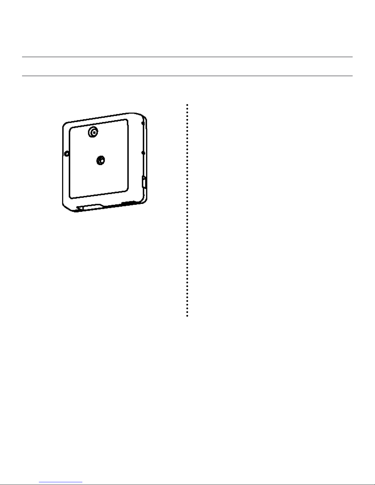
Identify Your Clock
A label containing the part number of your clock is attached to the clock movement.
P. 540-563-2000
F. 540-362-9800
www.valcom.com
ORIGINAL CLOCKS
V-A2412
V-A2416
V-A11012
V-A11016
B-MODEL CLOCKS
V-A2412B
V-A2416B
V-A11012B
V-A11016B
4
Page 5
Wall Mount Installation
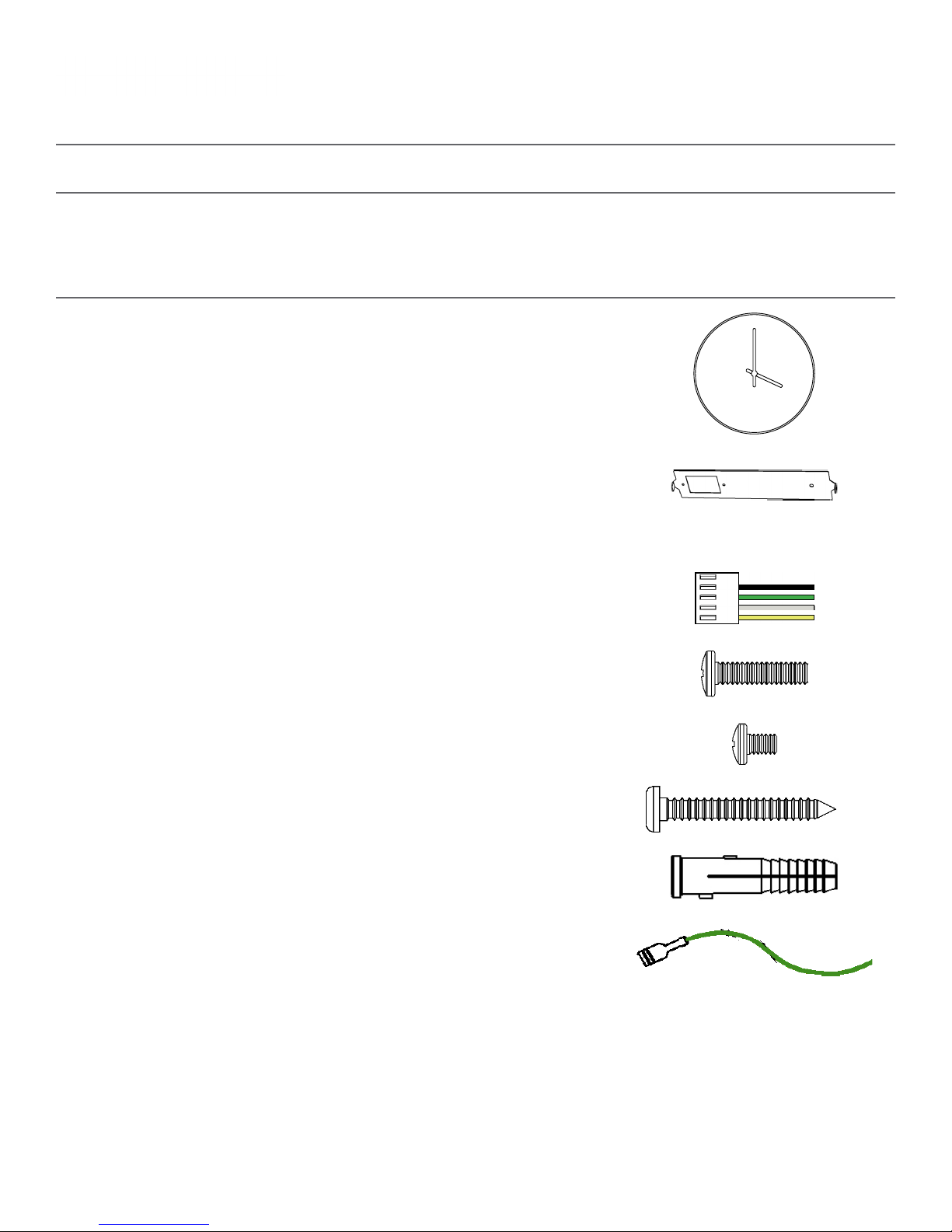
Included in Package
Valcom, Inc.
5614 Hollins Road
Roanoke, VA 24019
USA
P. 540-563-2000
F. 540-362-9800
www.valcom.com
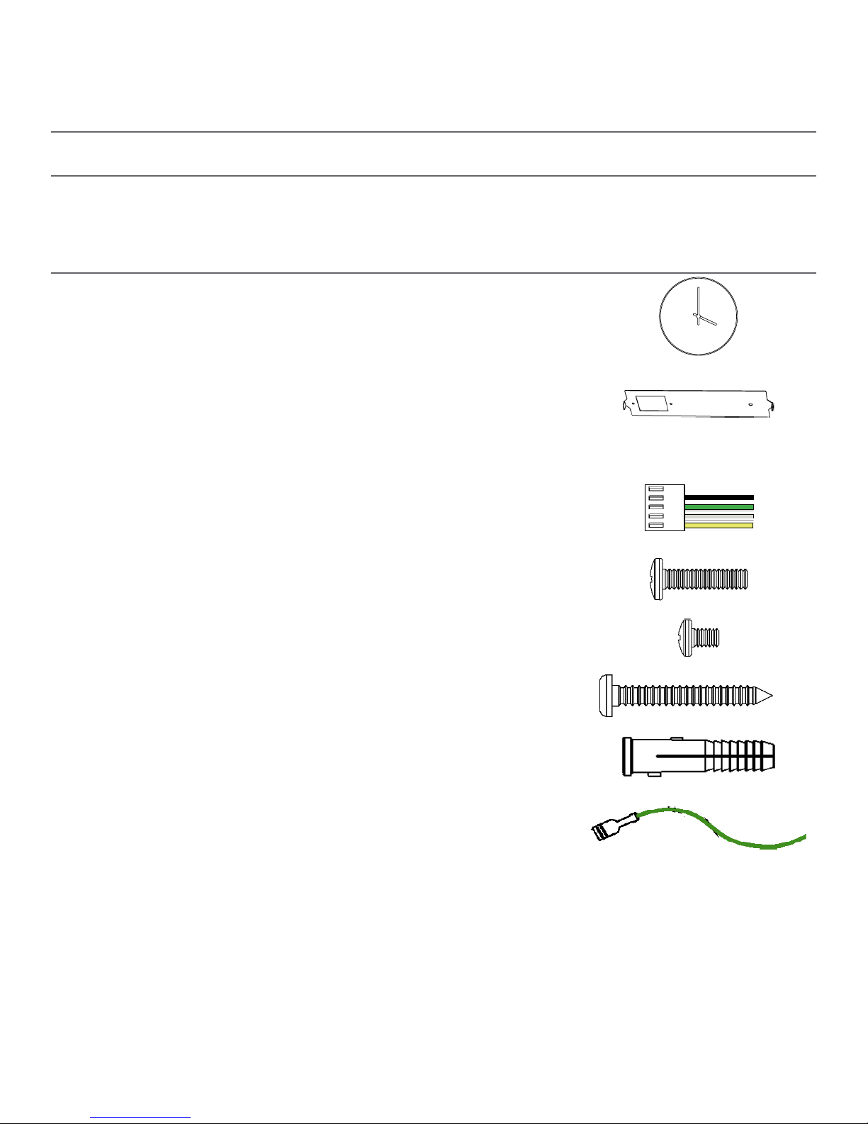
Description
Valcom analog clock
Mounting Bracket
12”: M- M B -12- 4
16”: M-MB-16 -2
Included in Wiring Kit (A-PK-12-2A)
Power/grounding wires
and connector
#6 -32x1/ 2 screw
Quantity
1
1
1
2
Picture
M4 - 0.5x10
#10x1.5 Self-tapping screw
Wall anchor
Additional grounding wire
2
1
1
1
with connector
PLEASE NOTE: A user will also have to provide a Phillips-head screwdriver, a small slot-head screwdriver, a drill with a 1/4 inch drill bit, a pencil, a single
gang box, any equipment needed to install the gang box, and any additional wiring needed to extend the signal, power, or ground cables.
If any of the items listed in the wiring kit are missing, you may contact Valcom and order a
replacement kit.
5
Page 6
Wall Mount Installation
Valcom, Inc.
5614 Hollins Road
Roanoke, VA 24019
USA
P. 540-563-2000
F. 540-362-9800
www.valcom.com
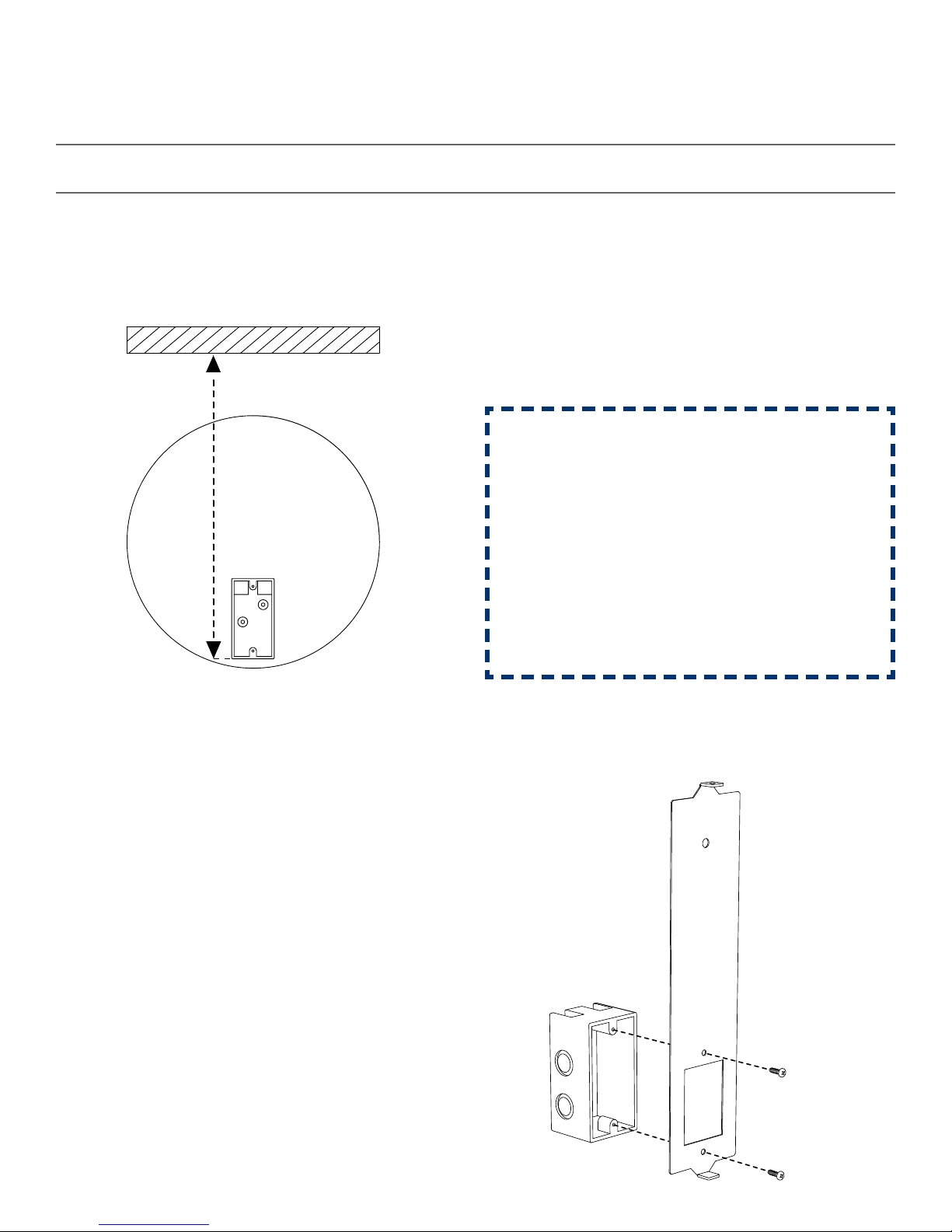
1) Install the single gang box in the wall. Leave at
least 17 inches between the bottom of the gang
box and ceiling. Confirm that the bottom of the
gang box is level with the floor.
1 2
17” Minimum
43.2 cm
2) Run power and communication wiring to the
gang box. See the sections of this manual labeled
“Wiring Information” for additional details,
depending on your system.
If you are using a 2-wire system, pull the
YELLOW and GREEN wires out of
the connector.
CHECK YOUR WIRING
The voltage between the white and black wires
should measure 105-126 volts AC in the 110
volt model or 21.5-26.5 21.5-26.5 volts DC in
the 24 volt model.
If you are using the 24 volt model, make sure
that the wiring leading to the clock is from a
Valcom power supply or V-VCU.
3) Attach the communication, power,
and grounding wires from your kit to the
communication and power wires in the gang box.
See the Wiring Guide included later in this manual
for additional details.
3
4) Use the #6-32x1/2 screws to attach the mounting
bracket to the gang box. The gang box should be at
the bottom of the mounting piece.
4
6
Page 7

Wall Mount Installation
Valcom, Inc.
5614 Hollins Road
Roanoke, VA 24019
USA
P. 540-563-2000
F. 540-362-9800
www.valcom.com
5) Use the pencil to mark the location of the large,
circular hole at the top of the mounting bracket.
Once finished, remove the mounting piece and drill
a hole at the location you just marked.
5
6) Insert the wall anchor into the hole, then reattach
the mounting bracket. This time, also insert the
#10x1.5 through the top of the mounting piece and
into the wall anchor.
6
7) Remove the gearbox pin, then, if the case is
made of metal, attach the grounding wire to the
grounding tab below and to the right of the
clock movement.
7
8) Attach the Power connector to the port on the
clock movement.
3-Wire Sync 2-Wire Digital
8
Black
Green
White
Yell ow
3-Wire Sync 2-Wire Digital
Black
White
Yell ow
White
Green
Black
White
Black
7
Page 8
Valcom, Inc.
5614 Hollins Road
Roanoke, VA 24019
USA
Wall Mount Installation
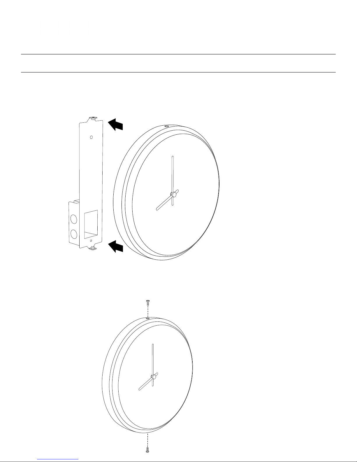
9) Attach the clock to the mounting piece so that the hole at the top of the clock lines up with the hole
at the top of the mounting piece, and the hole at the bottom of the clock lines up with the hole at the
bottom of the mounting piece.
P. 540-563-2000
F. 540-362-9800
www.valcom.com
9
10) Use the two M4-0.5x10 screws to attach the clock to the mounting bracket. The screws should
pass through the top and bottom holes on the clock, followed by the top and bottom holes of the
mounting bracket.
10
8
Page 9
Flag Mount Installation
Included in Package
Valcom, Inc.
5614 Hollins Road
Roanoke, VA 24019
USA
P. 540-563-2000
F. 540-362-9800
www.valcom.com
Description
Valcom analog clock
Mounting Bracket
Included in Wiring Kit (A-PK-12-2A)
Power/grounding wires
and connector
#6 -32x1/ 2 screw
M4 - 0.5x10
Quantity
1
1 (not used)
1
(not used)
2
2 (not used)
Picture
#8x1.5 Self-tapping screw
Wall anchor
Additional grounding wire
with connector
If any of the items listed in the kits are missing, you may contact Valcom and order a replacement kit.
1 (not used)
1 (not used)
1
Continued on next page
9
Page 10

Flag Mount Installation
Included in Adapter Kit (V-SMR12A) or (V-SMR16A)
Valcom, Inc.
5614 Hollins Road
Roanoke, VA 24019
USA
P. 540-563-2000
F. 540-362-9800
www.valcom.com
Description
Round Clock Adapter
Internal-tooth washer
#8-32x7/16 screw
Included in Pole Kit
Dual-mount pole, including
mounting plate
Quantity
1
4
4
1
Picture
#10-32x3/8 green screw
PLEASE NOTE: A user will also have to provide a Phillips-head screwdriver, a small slot-head screwdriver, a drill with a 1/4 inch drill bit, a pencil, a double
gang box, Four wall anchors that can support 50 lbs and a maximum screw size of 10x1.5”, four #8 screws for the wall anchors, four #6-32x1 screws
for attaching the mounting plate to the gang box, any equipment needed to install the gang box, and any additional wiring needed to extend the signal,
power, or ground cables.
1
If any of the items listed in the kits are missing, you may contact Valcom and order a replacement kit.
10
Page 11

Flag Mount Installation
Valcom, Inc.
5614 Hollins Road
Roanoke, VA 24019
USA
P. 540-563-2000
F. 540-362-9800
www.valcom.com
1) Install the double gang box in the wall or ceiling.
If you are installing the gang box in the wall, leave
at least eleven inches between the top of the
gang box and the ceiling. If you are installing the
gang box in the ceiling, leave at least eleven inches
between the gang box and the wall.
Ceiling
1
11” Minimum
2) Run power and communication wiring to the
gang box. See the sections of this manual labeled
“Wiring Information” for additional details,
depending on your system.
If you are using a 2-wire system, pull the
YELLOW and GREEN wires out of
the connector.
CHECK YOUR WIRING
The voltage between the white and black wires
should measure 105-126 volts AC in the 110
volt model or 21.5-26.5 21.5-26.5 volts DC in
the 24 volt model.
If you are using the 24 volt model, make sure
that the wiring leading to the clock is from a
Valcom power supply or V-VCU.
2
3) Detach the mounting plate from the mounting
pole by unscrewing the two screws. Set the screws
and pole aside for later.
3
4) Attach the mounting plate to the gang box using
only two of the four long silver #6-32x1 screws.
With the mounting plate as a guide, use the pencil
to trace the locations of the four larger holes at the
outer corners.
4
11
Page 12

Flag Mount Installation
Valcom, Inc.
5614 Hollins Road
Roanoke, VA 24019
USA
P. 540-563-2000
F. 540-362-9800
www.valcom.com
5) Remove the mounting plate and drill the four
holes that were just traced. Insert the four wall
anchors into the holes.
5
7) Thread any wiring through the mounting plate,
and attach a grounding wire to the mounting plate
using one of the larger centered holes and the
#10-32x3/8 screw.
6) Reattach the mounting plate, this time using all
four long, silver #8 screws, then insert the four
#6-32x1 screws through the mounting plate and
into the anchors.
6
8) Use a screwdriver to remove one of the end caps.
The end cap and screw that was used to secure it
will not be needed again during this installation.
7
8
12
Page 13

Flag Mount Installation
Valcom, Inc.
5614 Hollins Road
Roanoke, VA 24019
USA
P. 540-563-2000
F. 540-362-9800
www.valcom.com
9) Insert the four #8-32x7/16 screws through the
internal-tooth washers, then through the adapter,
and finally into the pole. Use a screwdriver to
tighten the screws so that the adapter does
not move.
9
10) Thread at least fifteen inches (38.1cm) of wiring
from the gang box through the bottom of the pole
until each wire exits through the hole in
the adapter.
10
Adapter hole
11) Attach the base of the pole to the mounting plate so that the lip is on the top of the base, and the
holes for the screws are on the bottom of the base. Hang the base on the mounting plate, attach the wires
from the bottom of the pole to the wires in the gang box, then screw the other side of the base onto the
mounting plate using the two black screws you set aside before.
2
11
1
1
2
WALL
CEILING
13
Page 14

Valcom, Inc.
5614 Hollins Road
Roanoke, VA 24019
USA
Flag Mount Installation
12) Attach the power connector to the wires you threaded through the pole. Consult the diagrams
below for additional help, or see the sections of this manual labeled “3-Wire Synchronous (Sync-Wire)
Communication Wiring Information” or “2-Wire Digital Communication Wiring Information” for additional
details, depending on your system.
P. 540-563-2000
F. 540-362-9800
www.valcom.com
Master Clock
To next
clock
Gang
Box
Ground
Green
Black
White
Yellow
CLOCK 1
Black
Green
White
Yellow
13) Remove the gearbox pin, then, if the case is
made of metal, attach the grounding wire to the
grounding tab below and to the right of the
clock movement.
27/24
26/23
Common
Power
To next
clock
Gang
Box
12
14) Attach a power connector to the port on the
bottom of the movement.
A1/B1/C1
A2/B2/C2
Black
White
2-Wire Digital3-Wire Sync
Black
White
V- CCU
CLOCK 1
13
3-Wire Sync 2-Wire Digital
14
Black
Green
White
Yell ow
3-Wire Sync 2-Wire Digital
Yell ow
White
Green
Black
Black
White
White
Black
14
Page 15

Valcom, Inc.
5614 Hollins Road
Roanoke, VA 24019
USA
Flag Mount Installation
15) Remove the outer adapter screws, then slide the clock onto the adapter in the rotation that you wish it
to be viewed. You should hear a snapping noise as the four clips on the adapter secure the clock in place.
Insert the screws again to complete the installation.
P. 540-563-2000
F. 540-362-9800
www.valcom.com
15
16) If you feel the need to detach the clock from the housing after the installation has been completed,
remove the outer adapter screws, press down on the latches, and gently pull on the rim of the clock until
the clock detaches.
16
15
Page 16

Double Mount Installation
Included in Package
Valcom, Inc.
5614 Hollins Road
Roanoke, VA 24019
USA
P. 540-563-2000
F. 540-362-9800
www.valcom.com
Description
Valcom analog clock
Mounting Bracket
Included in Double Mount Kit
Dual-mount pole, including
mounting plate and adapters
#10-32x3/8 green screw
Included in Wiring Kit (A-PK-12-2A)
Quantity
2
2 (not used)
1
1
Picture
Power/grounding wires and
connector
#6 -32x1/ 2 screw
M4 - 0.5x10
#8x1.5 Self-tapping screw
Wall anchor
Additional grounding wire
with connector
PLEASE NOTE: A user will also have to provide a Phillips-head screwdriver, a small slot-head screwdriver, a drill with a 1/4 inch drill bit, a pencil, a double
gang box, Four wall anchors that can support 50 lbs and a maximum screw size of 10x1.5”, four #8 screws for the wall anchors, four #6-32x1 screws
for attaching the mounting plate to the gang box, any equipment needed to install the gang box, and any additional wiring needed to extend the signal,
power, or ground cables.
2
4
(not used)
4 (not used)
2 (not used)
2 (not used)
2
16
Page 17

Double Mount Installation
Valcom, Inc.
5614 Hollins Road
Roanoke, VA 24019
USA
P. 540-563-2000
F. 540-362-9800
www.valcom.com
1) Install the double gang box in the wall or ceiling.
If you are installing the gang box in the wall, leave
at least eleven inches between the top of the
gang box and the ceiling. If you are installing the
gang box in the ceiling, leave at least eleven inches
between the gang box and the wall.
Ceiling
1
11” Minimum
2) Run power and communication wiring to the
gang box. See the sections of this manual labeled
“Wiring Information” for additional details,
depending on your system.
If you are using a 2-wire system, pull the
YELLOW and GREEN wires out of
the connectors.
CHECK YOUR WIRING
The voltage between the white and black wires
should measure 105-126 volts AC in the 110
volt model or 21.5-26.5 21.5-26.5 volts DC in
the 24 volt model.
If you are using the 24 volt model, make sure
that the wiring leading to the clock is from a
Valcom power supply or V-VCU.
2
3) Detach the mounting plate from the mounting
pole by unscrewing the two screws. Set the screws
and pole aside for later.
3
4) Attach the mounting plate to the gang box using
only two of the four long silver #6-32x1 screws.
With the mounting plate as a guide, use the pencil
to trace the locations of the four larger holes at the
outer corners.
4
17
Page 18

Double Mount Installation
Valcom, Inc.
5614 Hollins Road
Roanoke, VA 24019
USA
P. 540-563-2000
F. 540-362-9800
www.valcom.com
5) Remove the mounting plate and drill the four
holes that were just traced. Insert the four wall
anchors into the holes.
5
7) Thread any wiring through the mounting plate,
and attach a grounding wire to the mounting plate
using one of the larger centered holes and the
#10-32x3/8 screw.
6) Reattach the mounting plate, this time using all
four long, silver #8 screws, then insert the four
#6-32x1 screws through the mounting plate and
into the anchors.
6
8) Thread at least fifteen inches (38.1cm) of wiring
from the gang box through the bottom of the pole
until each wire exits through the hole in the adapter.
7
8
Adapter hole
18
Page 19

Valcom, Inc.
5614 Hollins Road
Roanoke, VA 24019
USA
P. 540-563-2000
F. 540-362-9800
www.valcom.com
Double Mount Installation
9) Attach the base of the pole to the mounting plate so that the lip is on the top of the base, and the holes
for the screws are on the bottom of the base. Hang the base on the mounting plate, attach the wires
from the bottom of the pole to the wires in the gang box, then screw the other side of the base onto the
mounting plate using the two black screws you set aside before.
2
9
1
1
2
CEILING
WALL
10) Attach the power connectors to the wires you threaded through the pole. Consult the diagrams
below for additional help, or see the sections of this manual labeled “3-Wire Synchronous (Sync-Wire)
Communication Wiring Information” or “2-Wire Digital Communication Wiring Information” for additional
details, depending on your system.
Master Clock
To next
clock
Gang
Box
27/24
26/23
Common
Power
To next
clock
10
Gang
Box
V- CCU
Ground
Green
Black
White
Yellow
3-Wire Sync
Black
White
CLOCK 1CLOCK 2
BlackBlack
GreenGreen
WhiteWhite
YellowYellow
2-Wire Digital
CLOCK 1CLOCK 2
BlackBlack
WhiteWhite
19
Page 20

Double Mount Installation
Valcom, Inc.
5614 Hollins Road
Roanoke, VA 24019
USA
P. 540-563-2000
F. 540-362-9800
www.valcom.com
11) Remove the gearbox pin, then, if the case is
made of metal, attach the grounding wire to the
grounding tab below and to the right of the
clock movement.
11 12
12) Attach a power connector to the ports on the
bottom of each movement.
3-Wire Sync 2-Wire Digital
Black
Green
White
Yell ow
3-Wire Sync 2-Wire Digital
Black
White
13) Remove the outer adapter screws, then slide
each clock onto the adapter in the rotation that you
wish it to be viewed. You should hear a snapping
noise as the four clips on the adapter secure the
clock in place. Insert the screws again to complete
the installation.
13
Yell ow
White
Green
Black
14) If you feel the need to detach the clock
from the housing after the installation has been
completed, remove the outer adapter screws, press
down on the latches, and gently pull on the rim of
the clock until the clock detaches.
White
Black
14
20
Page 21

Valcom, Inc.
5614 Hollins Road
Roanoke, VA 24019
USA
Wiring Information - 2-Wire Digital Communication
Valcom Master Clock
18 19
Data In
P. 540-563-2000
F. 540-362-9800
www.valcom.com
V-C6124P
+-+-+- +-+-+-
*V-C6124P and the V-CCU are
ordered as a V-VCU.
24 VDC IN24 volt outputs
V-CCU
2 Wire Digital
Output to Clocks
White
Black
V- A 2412 or V- A 2416
V-A2412B or V-A2416B
Orange
Yellow
V-D2425B or V-D2440 B
White
Black
V- A 2412 or V- A 2416
V-A2412B or V-A2416B
21
Page 22

Valcom, Inc.
5614 Hollins Road
Roanoke, VA 24019
USA
P. 540-563-2000
F. 540-362-9800
www.valcom.com
Warranty
Valcom, Inc. warrants its products only to the original purchaser, for its own use, to be free from defects in
materials and workmanship under conditions of normal use and service for a period of one year from the
date of shipment. This Limited Warranty obligation shall be limited to the replacement, repair or refund of
any such defective device within the warranty period, provided that:
1. Inspection by Valcom, Inc. indicates the validity of the claim;
2. The defect is not the result of damage, misuse or negligence after the original shipment;
3. The product has not been altered in any way or repaired by others and that factory sealed units
are unopened (a service charge plus parts and labor will be applied to units defaced or
physically damaged);
4. Freight charges for the return of products to Valcom are prepaid;
5. All units ‘out of warranty’ are subject to a service charge. The service charge will cover minor repairs
(major repairs will be subject to additional charges for parts and labor).
This Limited Warranty is in lieu of and excludes all other warranties, expressed or implied and in no event
shall Valcom, Inc. be liable for any anticipated profits, consequential damages, loss of time or other losses
incurred by the buyer in connection with the purchase, operation, maintenance, installation, removal or use
of the product. The maximum liability of Valcom under this warranty is limited to the purchase price of the
specific Product covered by the warranty.
Disclaimer. Except for the Limited Warranty provided herein, the product is provided “as-is”
without any warranty of any kind whatsoever including, without limitation, any WARRANTY
OF MERCHANTABILITY, FITNESS FOR A PARTICULAR PURPOSE OR NON-INFRINGEMENT.
This warranty specifically excludes damage incurred in shipment. In the event a product is received in
damaged condition, the carrier should be notified immediately. Claims for such damage should be filed
with the carrier involved in accordance with the F.O.B. point.
Headquarters:
Valcom, Inc.
5614 Hollins Road
Roanoke VA 24019-5056
Phone: (540) 563-2000 FAX: (540) 362-9800
22
Page 23

Valcom, Inc.
5614 Hollins Road
Roanoke, VA 24019
USA
Wiring Information - 3-Wire Synchronous (Sync-Wire)
Communication 24VDC
Valcom Master Clock
P. 540-563-2000
F. 540-362-9800
www.valcom.com
10 Amp Contact Rating
Clock Circuit
272426
or
23
Black
White
Power
Neutral
Reset
24VDC
Ground
27 26 25 24 23 22
or*
27 26 25 24 23 22
WhiteNeutral
BlackPower
YellowReset
Green
Clock Circuit 1
Clock Circuit 2
V- A 2412 or V- A 2416
V-A2412B or V-A2416B
* ”or” means one pair of ports or
the other. You cannot, for instance,
use port 23 for reset and 27 for
power, nor can you use 26 for reset
and 24 for power. You must use
the pair 24 AND 23 or the pair
26 AND 27
Ground
WhiteNeutral
BlackPower
YellowReset
Green
V- A 2412 or V- A 2416
V-A2412B or V-A2416B
23
Page 24

Valcom, Inc.
5614 Hollins Road
Roanoke, VA 24019
USA
Wiring Information - 3-Wire Synchronous (Sync-Wire)
Communication 110VAC
Valcom Master Clock
P. 540-563-2000
F. 540-362-9800
www.valcom.com
10 Amp Contact Rating
Clock Circuit
272426
or
23
Black
White
Power
Neutral
Reset
110VAC
Ground
27 26 25 24 23 22
or*
27 26 25 24 23 22
WhiteNeutral
BlackPower
YellowReset
Green
Clock Circuit 1
Clock Circuit 2
V- A11012 o r V - A11016
V-A11012B or V-A11016B
* ”or” means one pair of ports or
the other. You cannot, for instance,
use port 23 for reset and 27 for
power, nor can you use 26 for reset
and 24 for power. You must use
the pair 24 AND 23 or the pair
26 AND 27
Ground
WhiteNeutral
BlackPower
YellowReset
Green
V- A11012 o r V - A11016
V-A11012B or V-A11016B
24
Page 25

Valcom, Inc.
5614 Hollins Road
Roanoke, VA 24019
USA
P. 540-563-2000
F. 540-362-9800
www.valcom.com
Frequently Asked Questions
How do I know if the clock is receiving data?
Perform Diagnostic 2. See the section labeled “Diagnostic Test #2 - Comprehensive Test”. The result should
correspond to your system’s synchronization settings.
Example 1: The two-wire digital system should result in the clock recieving communication within the
last hour.
Example 2: Once-a-day sync systems may return a result of 11 hours or more, depending on when you
conduct the test. In this case, the test should be conducted less than nine hours after the synchronization
signal is sent.
What size utility/gang box is needed?
A standard single gang box is required for wall mounting a clock. However, if you are installing a double
mount or flag-mount clock, then a standard double gang box is required.
Do I need to power up all the clocks at the same time?
No. Clocks that are added to the system after power up will begin running and wait for correction signals
from the master clock. Sync-wire systems may take up to 24 hours to receive a correction signal.
Do I have to reset the clock if it suffers a power outage?
No. The clock will resume operation after the power outage, and will adjust to the correct time as soon as
it receives a signal from the master clock.
What happens if I power the Valcom Wired Clock before connecting the master clock?
The clock will begin to run, but the time displayed will be incorrect. As soon as signal wires from the
master clock are connected and a synchronization signal is sent, the Valcom Wired Clock will correct itself
to display the correct time.
Can I manually set the time on the clock?
No. Furthermore, attempting to open the front crystal or moving the hands manually will damage the clock
and void your warranty.
25
Page 26

Valcom, Inc.
5614 Hollins Road
Roanoke, VA 24019
USA
P. 540-563-2000
F. 540-362-9800
www.valcom.com
Questions about Protocols
How do I set up the Valcom Wired Clock to accept synchronization protocols from Rauland,
Dukane, and other systems?
If you are receiving the protocol directly from the master clock, your Valcom Wired Clock will automatically
detect the sync-wire protocol being used when it first powers up; no action on your part is required.
If you wish to use Valcom’s 2-wire digital protocol to carry synchronization data from a system that uses
an unsupported protocol, a Valcom Master Clock must be used as an adapter between the two wiring
systems. Consult the wiring guide in your Master Clock manual for more information.
How do I select which protocol I want my Valcom Wired Clock to use?
When you power up the clock, your Valcom Wired Clock will automatically recognize the protocol being
used as soon as it receives data.
Can I change protocols if the system is running?
Yes. There are two ways of doing this:
1) Do nothing. Within three days of being plugged into the new protocol, the Valcom Wired Clock will
automatically notice the change in protocol and correct itself.
2) Reset the clock to manufacturer’s default. Perform Diagnostic #3, then, after Diagnostic #3 is complete,
power cycle the clock.
How do I check to confirm that the Valcom Wired Clock is receiving the correct protocol?
Perform Diagnostic #1
How do I perform diagnostic tests on the clock system?
See the sections on the pages labeled “Diagnostic Test #1 - Protocol Verification”, “Diagnostic Test
#2 - Comprehensive Test”, or “Diagnostic Test #3 - Manufacturing Default”, depending on your needs.
I am adding a new clock into an existing Valcom Wired Clock System. Do I have to set my entire
system back to 12:00?
No. The new Valcom Wired clock will automatically correct itself upon receiving the data signal from the
master clock.
26
Page 27

Valcom, Inc.
5614 Hollins Road
Roanoke, VA 24019
USA
P. 540-563-2000
F. 540-362-9800
www.valcom.com
Troubleshooting
The clock is plugged into the power, but it is not running. What should I do?
a) Make sure that the movement’s gearbox pin is removed.
b) Make sure that the ground wire is not touching other wires.
c) Make sure that the transformer is an isolated transformer if using a 24 volt model.
d) Measure the voltage between the power (black) wire and the neutral (white) wire. The voltage between
the white and black wires should measure 105-126 volts AC in the 110 volt model or 21.5-26.5 21.5-26.5
volts DC in the 24 volt model.
*Failure to follow instructions c and d can result in a blown fuse.
The clock is not receiving a communication signal from the master clock. What should I do?
Follow these steps in order:
1) In order to check the last time the clock received communication from the master clock, perform
Diagnostic #2. See the section labeled “Diagnostic Test #2 - Comprehensive Test”
2) Compare the time that the last signal was recieved to the parameters of your protocol. If the amount of
time since the last signal was recieved is more than the amount of time since the clock last recieved time
data, then there is a fault with the system.
3) Check your master clock and confirm that it is sending time data at the correct protocol and at the
correct time. Consult your master clock manual for more information.
4) If your master clock has been properly configured, take the clock off the wall and test it at a location
close to the master clock’s signal output (or the converter box signal output, if a 2-Wire Digital System is
being used). Use the master clock to send time data to the clocks.
If the clock corrects itself, then there was a problem with the wiring to the clock’s original installation
point, and the wiring must be repaired or replaced.
If the clock still fails to correct itself, contact tech support.
I can hear data noise bleeding into the intercom line. What should I do?
Reduce the transmission rate from the master clock to once a minute. Please refer to the master clock
manual for information on how to change the transmission rate.
27
Page 28

Valcom, Inc.
5614 Hollins Road
Roanoke, VA 24019
USA
Diagnostic Test #1 - Protocol Verification (Original Only)
The purpose of Diagnostic #1 is to tell the user
which protocol the master clock is using to
communicate with the secondary clock.
Diagnostic #1 may be enabled by pressing the
diagnostic button for one second. If the
clock is performing this diagnostic, the Diagnostic
LED will flash green once every three seconds. It will
continue to flash once every three seconds until the
diagnostic is complete. The clock will confirm that
the diagnostic is complete when the LED shines a
different color.
If the LED is shining a solid green:
Button
LED
P. 540-563-2000
F. 540-362-9800
www.valcom.com
The Diagnostic was completed successfully. The
second hand on the clock will move to a specific
second on the dial. Each second corresponds to a
particular protocol and polarity:
Second Hand Position
2 seconds
4 seconds
6 seconds
8 seconds
10 seconds
12 seconds
14 seconds
16 seconds
18 seconds
20 seconds
Protocal and Polarity Detected
2-Wire Digital Communication, Polarity 1
2-Wire Digital Communication, Polarity 2
3-Wire Digital Communication, Polarity 1
3-Wire Digital Communication, Polarity 2
RS485 Communication, Polarity 1
RS485 Communication, Polarity 2
59 Minute Correction, Correct Polarity
59 Minute Correction, Reverse Polarity
58 Minute Correction, Correct Polarity
58 Minute Correction, Reverse Polarity
22 seconds
24 seconds
The second hand will remain on this number for 3 minutes, and then the clock will revert to displaying the
accurate time.
If the LED is flashing red:
A comprehensive test is required. Please perform Diagnostic #2
National Time/Rauland Correction, Correct Polarity
National Time/Rauland Correction, Reverse Polarity
28
Page 29

Valcom, Inc.
5614 Hollins Road
Roanoke, VA 24019
USA
Diagnostic Test #1 - Protocol Verification (B-Model Only)
The purpose of Diagnostic #1 is to tell the user
which protocol the master clock is using to
communicate with the secondary clock.
Diagnostic #1 may be enabled by pressing the
diagnostic button once. If the clock is performing
this diagnostic, the Diagnostic LED will flash green
once every three seconds. It will continue to flash
once every three seconds until the diagnostic is
complete. The clock will confirm that the diagnostic
is complete when the LED shines a different color.
If the LED is shining a solid green:
Green
LED
P. 540-563-2000
F. 540-362-9800
www.valcom.com
Button
Red
The Diagnostic was completed successfully. The
second hand on the clock will move to a specific
second on the dial. Each second corresponds to a
particular protocol and polarity:
Second Hand Position
2 seconds
4 seconds
6 seconds
8 seconds
10 seconds
12 seconds
14 seconds
16 seconds
18 seconds
Protocal and Polarity Detected
2-Wire Digital Communication, Polarity 1
2-Wire Digital Communication, Polarity 2
3-Wire Digital Communication, Polarity 1
3-Wire Digital Communication, Polarity 2
RS485 Communication, Polarity 1
RS485 Communication, Polarity 2
59 Minute Correction, Correct Polarity
59 Minute Correction, Reverse Polarity
58 Minute Correction, Correct Polarity
20 seconds
22 seconds
24 seconds
The second hand will remain on this number for 3 minutes, and then the clock will revert to displaying the
accurate time.
If the LED is flashing red:
A comprehensive test is required. Please perform Diagnostic #2
58 Minute Correction, Reverse Polarity
National Time/Rauland Correction, Correct Polarity
National Time/Rauland Correction, Reverse Polarity
29
Page 30

Valcom, Inc.
5614 Hollins Road
Roanoke, VA 24019
USA
Diagnostic Test #2 - Comprehensive Test (Original Only)
The purpose of Diagnostic #2 is to test the
Movement gearbox and electrical components of
your clock.
Diagnostic #2 may be enabled by holding down the
diagnostic button for three seconds. If the Valcom
Wired clock is performing this diagnostic, then a
green LED on the movement will flash twice every
three seconds. It will continue to flash twice every
three seconds until the diagnostic is complete. The
clock will confirm that the diagnostic is complete
when the LED shines a different color:
If the LED is shining a solid green:
Button
LED
P. 540-563-2000
F. 540-362-9800
www.valcom.com
The second hand will display the protocol and polarity that was detected. See the table on the previous
page for details.
The minute hand will display the software version number.
If the LED is flashing red:
The hour hand will display how much time has passed since the clock last received a communication signal:
Hour Hand Position
12
1
2
3
4
5
6
7
Time Since Clock Last Recieved Communication
Clock received communication within the last hour.
Clock received communication between 1 and 2 hours ago.
Clock received communication between 2 and 3 hours ago.
Clock received communication between 3 and 4 hours ago.
Clock received communication between 4 and 5 hours ago.
Clock received communication between 5 and 6 hours ago.
Clock received communication between 6 and 7 hours ago.
Clock received communication between 7 and 8 hours ago.
8
9
10
11
The clock hands will remain on these numbers for three minutes, and then the clock will revert to
displaying the accurate time.
Clock received communication between 8 and 9 hours ago.
Clock received communication between 9 and 10 hours ago.
Clock received communication between 10 and 11 hours ago.
Clock received communication more than 11 hours ago.
--May signify a manufacturer default.
30
Page 31

Valcom, Inc.
5614 Hollins Road
Roanoke, VA 24019
USA
Diagnostic Test #2 - Comprehensive Test (B-Model Only)
The purpose of Diagnostic #2 is to test the Movement
gearbox and electrical components of your clock.
Diagnostic #2 may be enabled by pressing the
diagnostic button twice. If the clock is performing
this diagnostic, then a green LED on the movement
will flash twice every three seconds. It will continue to
flash twice every three seconds until the diagnostic is
complete.
If the LED is lit a solid green:
The second hand will display the protocol and polarity
that was detected. See the table on the previous page
for details.
Green
LED
P. 540-563-2000
F. 540-362-9800
www.valcom.com
Button
Red
The minute hand will display the software version
number.
If the LED is flashing red:
The hour hand will display how much time has passed
since the clock last received a communication signal:
Hour Hand Position
12
1
2
3
4
5
6
7
8
Time Since Clock Last Recieved Communication
Clock received communication within the last hour.
Clock received communication between 1 and 2 hours ago.
Clock received communication between 2 and 3 hours ago.
Clock received communication between 3 and 4 hours ago.
Clock received communication between 4 and 5 hours ago.
Clock received communication between 5 and 6 hours ago.
Clock received communication between 6 and 7 hours ago.
Clock received communication between 7 and 8 hours ago.
Clock received communication between 8 and 9 hours ago.
9
10
11
The clock hands will remain on these numbers for three minutes, and then the clock will revert to
displaying the accurate time.
Clock received communication between 9 and 10 hours ago.
Clock received communication between 10 and 11 hours ago.
Clock received communication more than 11 hours ago.
--May signify a manufacturer default.
31
Page 32

Valcom, Inc.
5614 Hollins Road
Roanoke, VA 24019
USA
Diagnostic Test #3 - Manufacturing Default (Original Only)
The purpose of Diagnostic #3 is to bring the clock
back to 12:00:00 and reset to the manufacturer’s
default.
Diagnostic #3 may be enabled by holding down the
diagnostic button for five seconds. If the Valcom
Wired clock is performing this diagnostic, then a
green LED on the back will flash three times with
a five second break between each flash. The LED
will continue to flash green until the diagnostic is
complete. The clock will confirm that the diagnostic
is complete when the LED shines a different color.
If the LED is flashing red:
Button
LED
P. 540-563-2000
F. 540-362-9800
www.valcom.com
Number of Red Flashes
1,2
Error Message
Error detected in second hand. Confirm that hands
are not hitting each other, then repeat the test.
3,4,5
Error detected in the minute or hour hand. Confirm
that hands are not hitting each other, then repeat
the test.
6,7, 8
Call tech support.
If the LED is a solid green and all of the clock hands are pointing to 12, the test was completed successfully.
At the end of Diagnostic three, the clock hands will be set to 12:00:00. The clock will not resume normal
operation until the power has been recycled.
32
Page 33

Valcom, Inc.
5614 Hollins Road
Roanoke, VA 24019
USA
Diagnostic Test #3 - Manufacturing Default (B-Model Only)
P. 540-563-2000
F. 540-362-9800
www.valcom.com
The purpose of Diagnostic #3 is to bring the clock
back to 12:00:00 and reset to the manufacturer’s
default.
Diagnostic #3 may be enabled by pressing the
diagnostic button three times. If the clock is
performing this diagnostic, then a green LED on the
back will flash three times with a five second break
between each flash. The LED will continue to flash
green until the diagnostic is complete.
If the LED is flashing red:
Number of Red Flashes
1,2
3,4,5
Button
Green
Red
LED
Error Message
Error detected in second hand. Confirm that hands
are not hitting each other, then repeat the test.
Error detected in the minute or hour hand. Confirm
that hands are not hitting each other, then repeat
the test.
6,7, 8
Call tech support.
If the LED is a solid green and all of the clock hands are pointing to 12, the test was completed successfully.
At the end of Diagnostic three, the clock hands will be set to 12:00:00. The clock will not resume normal
operation until the power has been recycled.
33
 Loading...