

Page 1
(540) 427-3900
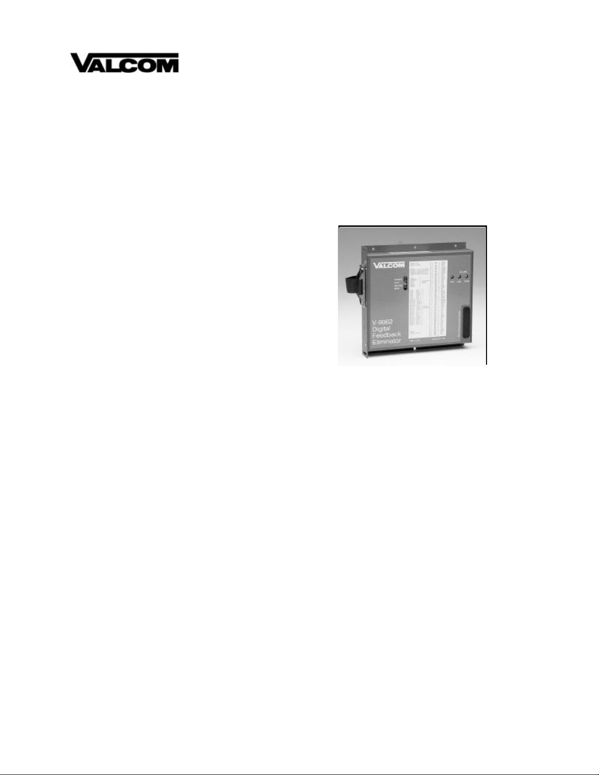
V-9962
DIGITAL FEEDBACK ELIMINATOR
VSP V-9962
Issue 2
GENERAL
The V -9962 is a Digital Feedback Eliminator designed to
eliminate paging system acoustic feedback with an
option to prevent DTMF tones from being broadcast
through the paging system.
SPECIFICATIONS
Features
! Two audio outputs
Line level 600 ohm
Low impedance 8 ohm
(transformer isolated and separately adjustable)
! Audio input, 600 ohm, transformer isolated
! Three output relays - Play, Record, Busy
! LED Indicators
! Easy access volume controls
! Dip switch programmable
! Solid state, no moving parts
! Audio, DTMF, or contact closure activated
! DTMF message cancel
! Easy to install in new and existing systems
Access
! DTMF (Dual Tone Multi-Frequency)
! VOX (Voice Operated Switch)
! Contact Closure
Dimensions & Weight
Dimensions:
! 19.05cm H x 20.32cm W x 3.18cm D
(7.5"H x 8.0"W x 1.25"D)
! Weight: 1.36 Kg (3.0 lbs.)
Nominal Specifications
Input Impedance: 600 ohms
Input Level: -10 dBm
Line Level Output Impedance: 600 ohms
Output Level: -10 dBm (adjustable)
Speaker Level Output Impedance: 8 ohms
1
Output Level: -10 dBm (adjustable)
VOX Sensitivity: -21 dBm (adjustable)
Release time after last sensed audio: 3 seconds
Nominal Power Requirements
! -24 VDC, 500 mA regulated "A" battery
Environment
Temperature: 0 to 40 Degrees C
Humidity: 0 to 85% non-precipitating
DESIGN
The V-9962 is designed to eliminate paging system
acoustic feedback with an option to prevent DTMF
tones from being broadcast through the paging system.
When a page is made, the message is digitized and
saved. Upon completion of the live page, the message
is released to play over the system speakers. This
eliminates the offensive squeal of feedback commonly
produced by telephones or microphones when making a
page.
947948
Page 2

Valcom
Zone
Page Control
Unit
Output
FIGURE 1 - SIMPLIFIED BLOCK DIAGRAM OF A TYPICAL INSTALLATION
INSTALLATION
Cabling
A 25 pair cable with a female amphenol connector
should be run from the feedback eliminator to a 66B
type punchdown block. The cable should be terminated
on the block in standard color code order. (See Figure
2).
Mounting
NOTE: DO NOT install the V-9962 or its wiring
closer than 18" to a power supply or any equipment
that generates electrical noise.
___ 1. Using four #6 - 1/2" wood screws, mount the
feedback eliminator in a vacant space on the
backboard.
___ 2. Mount a 66B type punchdown block near the
unit and label the block per Figure 2.
___ 3. Connect the 25 pair cable to the punchdown
block per standard color code order.
___ 4. Connect the female amphenol connector to the
V -9962.
Connections
___ 1. Connect zone output from a 600 ohm page port
or Valcom page control to Audio In Tip
(W/BL) and Audio In Ring (BL/W) on the
punchdown block. (See Note at end of this
section).
___ 2. Connect page enable contact closure (if
available - this is an optional connection) to
COM (R/BL) and RECORD (BL/R) on the
punchdown block.
V-9962
Up to 150 Valcom
Amplified Speakers
___ 3. Connect Tip lead or terminal of amplified
speaker(s) to output 2; speaker level 8Ω
(W/BR) on the punchdown block.
___ 4. Connect Ring lead or terminal of amplified
speaker(s) to output 2; speaker level return
(BR/W) on the punchdown block.
___ 5. Connect -24Vdc from a filtered -24Vdc power
supply to pin 24 (BR/V) on the punchdown
block.
___ 6. Connect GND of the power supply to pin 49
(V/BR) on the punchdown block.
___ 7. Plug in power supply.
___ 8. The POWER ON LED on the V-9962 should
illuminate. (IF POWER ON LED does not light,
then using a voltmeter, measure voltage
between power terminals with negative probe
at pin #24 and positive at pin #49. If reading is
reversed, unplug power supply, verify V/BR
and BR/V pairs are properly connected at the
punchdown block and connector).
See Figure 3 for simplified block diagrams of typical
configurations.
NOTE: The input level must be attenuated using a V1092 to prevent distortion if exceeding nominal input
levels for the V-9962; i.e., when used on a zone of
Valcom talkback page control (for one-way paging).
2
Page 3

W/BL
W/O
W/GR
W/BR
W/S
Audio In Tip
FIGURE 2 - CONNECTION BLOCK
Audio In Ring
---
--Output 1, Line level 600 ohm
Output 1, Line level return
Output 2, Spkr level 8 ohm
Output 2, Spkr level return
---
--COM
RECORD
COM
PLAY
COM
ABORT
---
--Play N.C.1
Play N.C.2
Play COM 1
Play COM 2
Play N.O.1
Play N.O.2
Record N.C.1
Record N.C.2
Record COM 1
Record COM 2
Record N.O.1
Record N.O.2
Busy 1 COM 1
Busy 1 COM 2
Busy 1 N.C.1
Busy 1 N.C.2
Busy 1 N.O.1
Busy 1 N.O.2
Busy 2 COM 1
Busy 2 COM 2
Busy 2 N.C.1
Busy 2 N.C.2
Busy 2 N.O.1
Busy 2 N.O. 2
---
---
---
--A GND
A BAT
---
---
Command
Inputs
Relay
Outputs
26
27
28
29
30
31
32
33
34
35
10
36
11
37
12
38
13
39
14
40
15
41
16
42
17
43
18
44
19
45
20
46
21
47
22
48
23
49
24
50
25
1
2
3
4
5
6
7
8
9
BL/W
O/W
GR/W
BR/W
S/W
R/BL
BL/R
R/O
O/R
R/G
G/R
R/BR
BR/R
R/S
S/R
BK/BL
BL/BK
BK/O
O/BK
BK/G
G/BK
BK/BR
BR/BK
BK/S
S/BK
Y/BL
BL/Y
Y/O
O/Y
Y/G
G/Y
Y/BR
BR/Y
Y/S
S/Y
V/BL
BL/V
V/O
O/V
V/G
G/V
V/BR
BR/V
V/S
S/V
3
Page 4

PAGE
Amplified Speakers
Amplified Speakers
(Power connections not shown)
PORT
ACCESS
LOOP
START
TRUNK
PORT
ACCESS
Audio
Contact
Closure
(optional)
Tip
Ring
T
R
VALCOM
Single or
Multi-Zone
Control
Unit
Tip
Ring
Record
Com
V-9962
Zone
Output
Contact
Closure
(optional)
8 Ohm
Out
Tip
Ring
Record
Com
Up to 150 Valcom
Amplified Speakers
V-9962
8 Ohm
Out
Up to 150 Valcom
VALCOM
C. O. LINE,
CENTREX
OR PABX
STATION
LEVEL
ACCESS
OUTPUT
TO A
Tip
Ring
V-9940 OR V-9950
T
R
V-9962
600 Ohm
Output
600 ohm
Out
Contact
Closure
(optional)
Audio
Input
V-9962
Tip
Ring
Record
Com
8 Ohm
Out
Output
TRADITIONAL
AMPLIFIER
Play COM 1
Play N.O. 1
Mute
Contact
FIGURE 3 - SIMPLIFIED BLOCK DIAGRAM OF TYPICAL CONFIGURATIONS
Up to 150 Valcom
25 or 70V
Speakers
4
Page 5

Setting Program Dip Switches
FIGURE 4
There are two sets of dip switches on the V-9962 (See
Figure 4) which provide user selectable Options.
1 2 3 4 5 6 7 8
SW272-1 SW272-2
1 2 3 4
On
The 8-position dip switch (SW-272-1)
offers the following choices:
Maximum Recording Length:
#1 Off 60 sec. at 3.4 Khz Bandwidth
#1 On 30 sec. at 6.8 Khz Bandwidth
DTMF Options:
#2 Off, #3 Off DTMF, No restrictions
#2 On, #3 Off DTMF, Allow two bursts
#2 Off, #3 On DTMF, Allow one burst
#2 On, #3 On DTMF, Choke (Abort)
Record Setup:
#4 On, #5 Off Activate RECORD by DTMF (One
Pulse).
#4 Off, #5 On Activate RECORD by Audio Sensor.
NOTE: Activate RECORD by external dry contact is
always functional regardless of switch settings.
Play Setup:
#6 Off, #7 Off Play while active by external contact.
#6 On, #7 Off Play once active by external contact.
#6 Off, #7 On Auto-repeat once. No external
contact needed.
#6 On, #7 On Auto-repeat twice.
#8 On Play Pre-page tone.
5
The 4-position dip switch (SW-272-2)
offers the following selections:
Page Delay:
(Delay time after recording ends before page play).
#1 Off, #2 Off 1 second delay.
#1 On, #2 Off 3 second delay.
#1 Off, #2 On 5 second delay.
#1 On, #2 On 10 second delay.
#3 and #4 - Spare switches.
Typical dipswitch setting is:
SW272-1 SW272-2
#1 ON #1 OFF
#2 ON #2 OFF
#3 ON #3 N/A
#4 OFF #4 N/A
#5 ON
#6 OFF
#7 ON
#8 OFF
Volume Control Setup
There are three volume controls on the V -9962.
VOX - Adjusts the voice sensitivity of the record by
VOX or DTMF activation. (Typical
adjustment of this control is completely
clockwise).
LINE - Adjusts level of page from Output 1 line level
600Ω output.
SPKR- Adjusts level of page from Output 2 speaker
level 8Ω output.
OPERATION
For proper operation, the V-9962 must receive a
RECORD command. This command will be from an
external source in the form of:
1. External dry contact closure: Between
terminals #6 (BL/R)(Record), and #31
(R/BL)(Com). The unit will record as long as
the contact closure is supplied to the unit or
until the maximum record time is reached.
When the Closure signal is removed, the V9962 automatically switches modes to re-play
the "just recorded" page. The re-play will be
played according to options selected during
set-up.
Page 6

2. DTMF Digit sent on audio lines: If the paging
system allows DTMF tones to be generated
by paging stations, the V-9962 can be
activated by enabling its internal detector to
start Recording. Recording will end
approximately 3 seconds after audio detection
ends. (If switches 2 and 3 of SW272-1 are in
the "on" position, this enables DTMF abort.
This allows the paging party to cancel their
message by pressing any button on their
telephone tone pad during recording).
3. Voice Operation (VOX): Recording will begin
at the start of actual paging; recording will end
approximately 3 seconds after the completion
of the page.
4. Play External Contact: By applying a dry
contact closure between COM (R/O) and Play
(O/R), the V-9962 will play the last recorded
message.
5. Auto Repeat Setup: The unit is normally set to
automatically playback the "just finished"
page as soon as the RECORD contact goes
away. This feature allows the user to set the
number of automatic repeats, one or two.
6. Pre-page Tone: This option inserts an alert
tone (the DTMF number 0) prior to the autorepage function.
7. Page Delay: This option inserts the selected
time delay between the end of record and the
time PLAY relay is activated and plays back
the recorded page.
TECHNICAL ASSISTANCE
When trouble is reported, verify the unit is turned on
and there are no broken connections leading to the unit.
Assistance in troubleshooting is available from the
factory. When calling, you should have a VOM and a
telephone test set available and be calling from the job
site. Call (540) 427-3900 and ask for an Applications
Engineer.
VALCOM equipment is not field repairable. VALCOM
maintains service facilities in Roanoke, VA. Should
repairs be necessary, attach a tag to the unit clearly
stating your company name, address, phone number,
contact person, and the nature of the problem. Send the
unit to the Repair and Return Dept. at the address
shown below.
VALCOM LIMITED WARRANTY
Valcom, Inc. warrants its products to be free from the defects in materials and workmanship under conditions of normal use and
service for a period of one year from the date of shipment. The obligation under this warranty shall be limited to the replacement,
repair or refund of any such defective device within the warranty period, provided that:
1. inspection by Valcom, Inc. indicates the validity of the claim,
2. the defect is not the result of damage, misuse, or negligence after the original shipment,
3. the product has not been altered in any way or repaired by others and that factory sealed units are unopened (A service charge
plus parts and labor will be applied to units defaced or physically damaged),
4. freight charges for the return of products are prepaid,
5. all units 'out of warranty' are subject to a service charge. The service charge will cover minor repairs (Major repairs will be
subject to additional charges for parts and labor).
This warranty is in lieu of and excludes all other warranties, expressed or implied, and in no event shall Valcom, Inc. be liable
for any anticipated profits, consequential damages, loss of time or other losses incurred by the buyer In connection with the
purchase, operation or use of the product.
This warranty specifically excludes damage incurred in shipment. In the event a product is received in damaged condition, the
carrier should be notified immediately. Claims for such damage should be filed with the carrier involved in accordance with the F. O.
B. point.
Headquarters:
Valcom, Inc.
1111 Industry Avenue
Roanoke, VA 24013
Phone: (540) 427-3900
FAX: (540) 427-3517
In Canada:
CMX Corporation
35 Van Kirk Drive #11 and 12
Brampton, Ontario L7A1A5
Phone: (905) 456-1072
FAX: (905) 456-2269
6
 Loading...