

Page 1
V-9947A
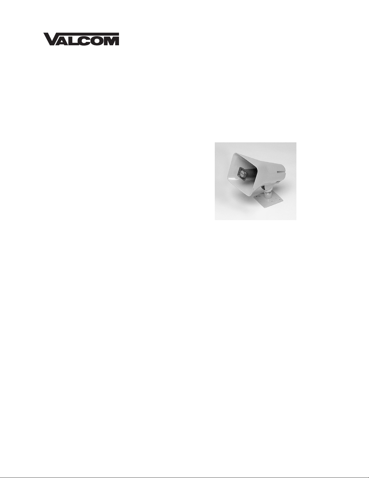
LINE POWERED LOUD RINGER/HORN
INTRODUCTION
The V-9947A, is a Line Powered Loud
Ringer/Horn which provides amplified electronic
tones for signaling in large or noisy areas. This
instruction contains the specifications and
information necessary to install, operate and
maintain the
V-9947A.
SPECIFICATIONS
Design
The V-9947A is a ringer/horn containing circuitry
to generate incoming call indication via a warble
or single tone when activated by 70-120VAC ring
voltage (Ringer Equivalency Number 2.7A).
To plan a system utilizing the V-9947A, refer to
the Ringer Distance Chart to determine
approximate distances covered. The number
given (ft) is the side to side distance for mounting
the speakers. It is also the distance in front of
the speaker that a good quality signal can be
heard.
Application
• PABX station ringer
Issue 10
• Single or warble tone output.
• Activated by 70-120VAC ring voltage.
• Tones continuous for duration of ring cycle.
• Weatherproof.
• Units may be multipled for simultaneous
access.
• Separate power supply not required.
Dimensions/Weight
• 6.5"H x 8.2"W x 10.4"D, plus mounting
bracket.
• (16.51cm H x 20.83cm W x 26.42cm D)
• 3.3 lbs. (1.5 kg)
Features
• Omni-directional mounting bracket.
• Self-contained tone generator, amplifier,
volume control and horn speaker.
Power Requirements
• 20-30Hz, 35mA maximum.
Environment
• Temperature: -20 to +55° C
• Humidity: 0-95% non-precipitating
1 947947
Page 2

INSTALLATION
Lead Connections
Connect the tip (green) and ring (red) leads of the
ringer to the PBX Analog station port.
• To produce a warble tone, the black and white
leads remain unconnected.
• To produce a single tone, connect the black
and white leads to each other (See Figure 3).
The V-9947A is not intended for direct or indirect
connection to the public telephone network or any
telephone line providing dial tone. When used with
a customer premise telephone system such as a
key system or PABX system, these units are
interfaced to the system via a fully protected page
port or system central office port, which is a fully
protected interface device. Also, the host system
must be configured to disallow central office trunk
conferencing in order to prevent indirect
connection to the public network.
Connecting Speaker to Base
The speaker may be attached to the base before
or after the base is mounted.
• Loosen position adjustment knob.
• Insert the ball of the base into the socket of the
speaker.
• Tighten the position adjustment knob.
Mounting
The V-9947A should be mounted 12' to 25' high to
obtain optimum results. This ringer may be used
for either interior or exterior signaling applications.
• Mount the base to a wall using the two holes
provided. Knockout holes are provided for
punch out should additional holes be desired.
• A "C" clamp is provided with the ringer to allow
mounting to a beam. Place the bolt through
the hole in the bottom of the base to secure
the "C" clamp to the beam. (See Figure 1). It
is suggested that the horn be mounted to the
underside of the "I" beam so as to provide the
maximum of positioning adjustments.
• Connection to an electrical backbox is
accomplished by channeling wire through the
ball of the base and making appropriate
connections. The base has holes punched for
a double-gang square box, but by punching
out additional knockout holes, the base can be
mounted to a single-gang or octagon box.
(See Figure 2).
The V-9947A may be rotated or moved up and
down to obtain the desired position by loosening
the position adjustment knob at the bottom of the
unit (See Figures 1 and 2) approximately 1 turn.
Make required adjustment and re-tighten the knob.
TECHNICAL ASSISTANCE
When trouble is reported, verify there are no
broken connections between the telephone and
the ringer. Ascertain volume control is turned
up.
Assistance in troubleshooting is available from
the factory. When calling, you should have a
VOM and a test set available and call from the
job site. Call (540) 563-2000 and press 1 for
Technical Support or visit our website at
www.Valcom.com.
Valcom equipment is not field repairable.
Valcom, Inc. maintains service facilities in
Roanoke, VA. Should repairs be necessary,
attach a tag to the unit clearly stating company
name, address, phone number, contact person,
and the nature of the problem. Send the unit to:
Valcom, Inc.
Repair and Return Dept.
5614 Hollins Road
Roanoke, VA 24019-5056
Ambient
Noise
Level
(dB)
dB
100
90
80
70
RINGER DISTANCE CHART
10 20 30 40 50 60 70 80 90 100 110 120 ft.
Distance (Spacing) in Feet
2
Page 3

"C" Clamp
A
A
x
Speaker Base
I-Beam
Position
djustment
Knob
Figure 1 - Mounting to a Beam with a "C" Clamp
Electrical
Backbox
Position
djustment
Knob
Wire
Speaker
Base
Figure 2 - Mounting to an Electrical Backbo
3
Page 4

Valcom, Inc. warrants its products to be free from defects in materials and workmanship under conditions of normal use and service for
g
VALCOM LIMITED WARRANTY
a period of one year from the date of shipment. The obligation under this warranty shall be limited to the replacement, repair or refund
of any such defective device within the warranty period, provided that:
1. inspection by Valcom, Inc. indicates the validity of the claim,
2. the defect is not the result of damage, misuse, or negligence after the original shipment,
3. the product has not been altered in any way or repaired by others and that factory sealed units are unopened
4. freight charges for the return of products to Valcom are prepaid,
5. all units 'out of warranty' are subject to a service charge. The service charge will cover minor repairs
This warranty is in lieu of and excludes all other warranties, expressed or implied, and in no event shall Valcom, Inc. be liable
for any anticipated profits, consequential damages, loss of time or other losses incurred by the buyer in connection with the
purchase, operation or use of the product.
This warranty specifically excludes damage incurred in shipment. In the event a product is received in damaged condition, the carrier
should be notified immediately. Claims for such damage should be filed with the carrier involved in accordance with the F.O.B. point.
(A service charge plus parts and labor will be applied to units defaced or physically damaged),
(Major repairs will be subject to additional charges for parts and labor).
Headquarters:
Valcom, Inc.
5414 Hollins Road
Roanoke, VA 24019
Phone: (540) 563-2000
FAX: (540) 362-9800
35 Van Kirk Drive #11 and 12
Brampton, Ontario L7A 1A5
In Canada:
CMX Corporation
Phone: (905) 456-1072
FAX: (905) 456-2269
Analog
Station Port
FIGURE 3
V- 9947A
Ti
Ring
--
Connect together to
Produce sin
Warble tone is produced
-when not connected.
Gree
Red
White
Black
le tone
4
Page 5

5
 Loading...