

Page 1
VSP-V-9941A
Issue 4
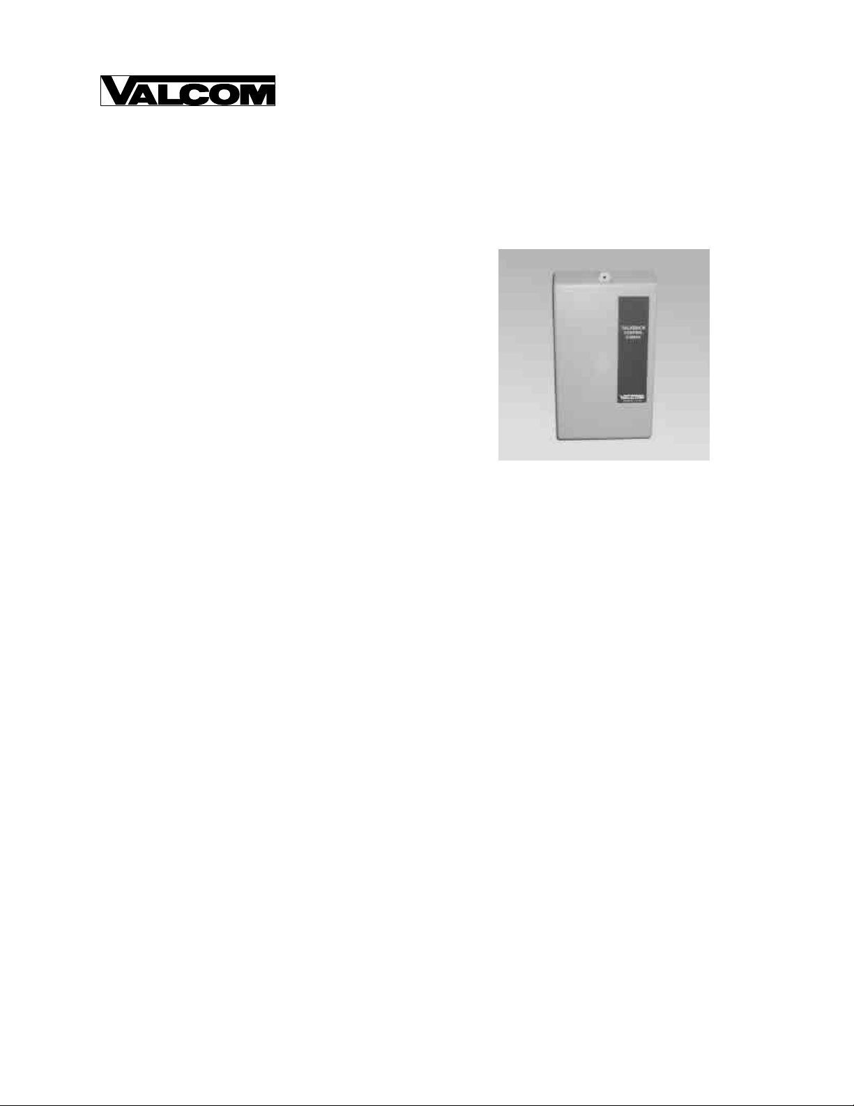
V-9941A
ONE ZONE HANDSFREE TALKBACK CONTROL UNIT
INTRODUCTION
The V-9941A is a One Zone Handsfree Page Unit for
use on an Electronic Key system line key position, a
PABX loop start trunk port, a dedicated single line
telephone or a 600 Ohm two-way page port with a
contact closure.
These instructions contain the specifications and
information necessary to install, operate and maintain
the One Zone Handsfree Talkback Control Unit.
SPECIFICATIONS
Purpose
• Provides battery feed and loop detect circuitry to
properly interface with a telephone system C. O.
position or dedicated single line telephone.
• Provides VOX circuit and handsfree amplifier to
drive 45 Ohm talkback speakers.
• Provides 600 Ohm input with ground start input
to operate on E-Key systems with a 600 Ohm
two- way page port and a contact closure.
Applications
• PABX loop start trunk port
• Electronic key system C. O. Line position
• Telephone systems with 600 Ohm two-way page
port and contact closure
• Dedicated single line telephone
Refer to Figure 1 for a block diagram of a typical
installation.
NOTE: When used with additional
equipment, the V-9941A can also be
accessed from a push-to-talk microphone for
use in restaurant drive-in windows and other
similar applications. Contact Valcom
Application Engineering for information.
Features
• Loop start
• Input for ground start from a contact closure
• Provides optional battery feed
• Built in talkback amplifier
• Directly drives up to two talkback speakers
• Will drive Valcom one-way amplified speaker
assemblies
• Screw terminals for all connections
• Initial alert tone option
• Repeated alert tone option
• Music input
• Speaker inhibit option
• Operates on -24VDC "B" Battery
Limitations
• Maximum of two Valcom talkback speakers plus
40 one-way amplified speaker assemblies.
• Maximum allowable cable distance from control
unit to talkback speakers is 800 feet.
Capacity
• Each V-9941A will provide one zone of talkback
paging
• The V-9941A is a single talkpath unit
• Each V-9941A will drive up to two 45 Ohm
talkback speakers
• Up to 40 one-way amplified speaker assemblies
may be used in addition to the talkback speakers
1 947960
Page 2

V-9941A
Electronic Key
or PABX
Page Port Access (600 Ohms) with
Contact Closure
C. O. Line
Position or
Loop Start
Trunk Port
Figure 1 - Typical Loop Start Trunk Installation
Power
Supply
Talkback
Speaker
Dimensions/Weight
• 8.25" H x 4.65" W x 2.30" D
(20.96cm H x 11.81cm W x 5.84cm D)
• 1.5 lbs. (0.68 kg)
Power Requirements
• 21.5 to -26VDC "B" Battery, 300mA maximum
Environment
Temperature: 0 to +50° C
Humidity: 0 to 85% (non-precipitating)
SYSTEM DESIGN
General
The Valcom V-9941A talkback control unit is
designed to provide paging access from a C. O.
position or loop start trunk port of a telephone
system. The V-9941A may also be connected to a
600 Ohm two-way page port with a contact closure or
a dedicated single line telephone. The V-9941A
contains all the VOX and handsfree amplifier
circuitry required to drive up to two Valcom 45 Ohm
talkback speakers.
Electronic Key, PABX Access or
Dedicated Single Line Telephone
The following components are required when paging
from a PABX loop start trunk port, Electronic Key
System C. O. line position or a Dedicated Single Line
Telephone:
A telephone system C. O. line port or PABX loop
start trunk port with a circuit card installed or a
dedicated single line telephone:
(1) V-9941A talkback control unit
(1) VP-624B power supply
45 Ohm talkback speakers (maximum two)
The following components are required when paging
from a 600 Ohm two-way paging port:
600 Ohm two-way paging port with contact closure
(1) V-9941A talkback page control
(1) VP-624B power supply
45 Ohm talkback speaker (maximum two)
Background Music
The V-9941A provides background music input and
is designed to automatically cut off the music during a
page. If background music is to be installed, a
receiver providing an 8 Ohm output with 1-3 Watts of
output power will be required.
Inhibit Option
The V-9941A is equipped with an inhibit lead that
may be used in special applications to automatically
turn off the speakers and allow a handset
conversation between the calling party and a single
line telephone connected to the paging Tip and Ring.
To use the inhibit function you will need a dedicated
single line telephone modified for "A" Lead Control
and a 5.1K Ohm 1/4 Watt resistor.
INSTALLATION
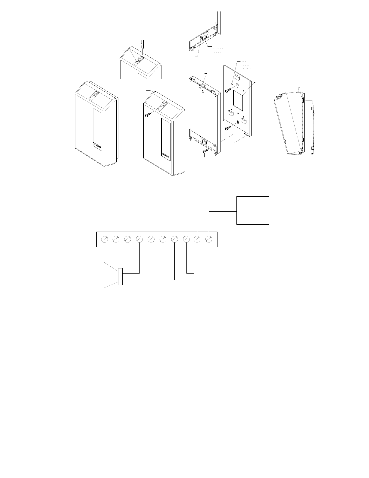
Mounting
Remove the metal mounting plate from the rear of the
V-9941A enclosure. Using two #6 ¾ inch wood
screws, mount the plate in a vacant space on the
backboard with the telephone system common
equipment. Both mounting holes must be utilized to
insure secure mounting of the unit. See Figure 1A.
Open the V-9941A enclosure to access connections
and option switches. Slide the rear of the unit
(contains the board) onto the mounting plate and lock
in place with screw provided. Make connections.
Replace cover and lock in place with the #6 ¾ inch
screw provided.
2
Page 3
TO REMOVE COVER
LOOSEN SCREW,
THEN ACTIVATE LATCH
PLASTIC
COVER
V-9941A
WIREWAY OPENING
TO WALL PLATE AND
JUNCTION BOX
CIRCUIT BOARD
HOUSING ASSEMBLY
SNAP LATCH
FIGURE 1A
WIRE TIE LOOP
WIRE TIE USED TO BUNDLE
ENTERING AND LEAVING TERMINAL
METAL WALL
MOUNTING
PLATE
BRACKET
LOCKING
SCREW
.155 DIA. HOLES FOR MOUNTING
SINGLE OR DOUBLE GANG JUNCTION
HOLE PATTERN MATCHES BOTH
AND US JUNCTION BOXES
1.5 x 2 WIRE ACCESS OPENING
TO JUNCTION BOX
R
T
SNAP LATCH
FOR COVER
Music
Music
Spkr
Inhibit
10
9 7
8
Spkr
6
Gnd Start
5
-24VDC
4
Ground
3
Ring
Tip
2
1
Ground (+)
-24VDC
C.O. Line Position
or Loop Start
Trunk Port
45 Ohm Talkback Speaker
ELECTRONIC KEY SYSTEM OR PABX ACCESS
INSTALLATION
WIRING INSTRUCTIONS:
__ b. "SW2" controls the repeated alert tone.
Place a check by each step as it is completed:
__ 1. Connect Tip of the telephone system trunk
position to the V-9941A terminal 1 (TIP).
__ 2. Connect Ring of the trunk port to the
__ c. "SW3" turn ON (Battery Feed Switch).
__ 5. Plug in power supply.
NOTE: "A" battery may be substituted for "B"
V-9941A terminal 2 (RING).
__ 3. Connect Tip and Ring of the talkback
__ 6. Connect -24VDC "B" battery (may be
speakers to the V-9941A terminals 6 and 7
(SPKR) of the V-9941A.
4. Option Switches:
__ a. "SW1" controls the initial alert tone. Turn
__ 7. Connect -24VDC "B" ground ("+" or "signal
the switch ON to precede each page with an
3
audible tone.
Turn the switch ON to have a short tone
burst every 15 seconds during a handsfree
page.
battery.
referred to as "-" or "signal battery") from
power supply to terminal 4 (-24VDC) on the
V-9941A.
ground") from power supply to terminal 3
(GND).
Page 4

ELECTRONIC KEY PAGE PORT CONNECTIONS
Electronic Key System
Contact
Closure
V-9941A
R
T
Inhibit
10
Music
Music
9 7
8
Spkr
Spkr
6
Gnd Start
5
-24VDC
4
Ground
3
Tip
Ring
2
1
Page Port
Ground (+)
-24VDC
45 Ohm Talkback Speaker
__ 8. Connect -24VDC ground (+) from power
supply to telephone system GROUND.
WIRING INSTRUCTIONS:
__ 1. Connect Tip of the telephone system 600
Ohm page port to terminal 1 (TIP) of the
V-9941A.
__ 2. Connect Ring of the 600 Ohm page port to
terminal 2 (RING).
__ 3. Connect one side of the telephone system
dry contact closure to terminal 3 (GND) of
the V-9941A.
__ 4. Connect the other side of the contact closure
to terminal 5 (GND ST) of the V-9941A.
__ 5. Connect Tip and Ring of the talkback
speakers to the V-9941A terminals 6 and 7
(SPKR).
6. Option Switches:
__ a. "SW1" controls the initial alert tone. Turn
the switch ON to precede each page with an
audible tone.
__ b. "SW2" controls the repeated alert tone.
Turn the switch ON to have a short tone
burst every 15 seconds during a handsfree
page.
__ 7. Plug in power supply.
NOTE: "A" battery may be substituted for
"B" battery.
__ 8. Connect -24VDC "B" battery (may be
referred to as "-" or "signal battery") from
power supply to terminal 4 (-24VDC) on the
V-9941A.
__ 9. Connect -24VDC "B" ground ("+" or "signal
ground") from power supply to terminal 3
(GND).
__ 10. Connect -24VDC ground (+) from power
supply to telephone system GROUND.
__ 11. " SW3 " turn to the OFF position (Battery
Feed Off).
RAT
15 Sec Tone
Initial Tone
IATE
Phone to Speaker
Speaker to Phone
Battery Feed
Location of Screw Terminals,
Option Switches and Volume Controls
V-9941A One Zone Talkback Control
Music
Music
Inhibit
10
9 78 6
SCREW CONNECTION DESIGNATIONS
Spkr
OFF
ON
Spkr
5
OFF
ON
Gnd Start
-24VDC
4 3 2 1
SW1
SW3
Ground
Ring
Tip
4
Page 5

Volume Adjustments
There are two volume controls on the V-9941A. The
control on the left adjusts the speaker to phone level
and the control on the right adjusts the phone to
speaker level. Turn the controls clockwise to
increase the volume.
__ a. Speaker to Phone:
Adjust this control so the reply from the speaker is
clear. IMPORTANT: This is the most critical
adjustment. Set the volume at the lowest practical
level. Setting this control too high will increase
background noise without giving greater talkback
volume.
__ b. Phone to Speaker:
Adjust this control to give the desired listening level
at the speakers.
Optional Connections
A) MUSIC:
__ 1. Connect a pair from an amplified music
source to terminals 8 and 9 (MUSIC) of the
V-9941A.
__ 2. Adjust the control on the music source for
the desired music level at the speakers.
B) INHIBIT CONNECTIONS:
__ 1. Verify the telephone being used has been
modified for "A" Lead Control. Contact the
telephone manufacturer for assistance if
required.
__ 2. Connect Tip of the Telephone to terminal 1
of the V-9941A.
__ 3. Connect Ring of the Telephone to terminal
2.
__ 4. Connect the “A1” Lead of the Telephone to
the V-9941A terminal 3.
__ 5. Connect the “A” Lead of the Telephone to
one end of a 5.1K Ohm 1/4 Watt resistor.
__ 6. Connect the other end of the resistor to
V-9941A terminal 10.
Telephone System C.O. Line Position
or Loop Start Trunk Port
OPERATION
The V-9941A provides a -24VDC battery feed on Tip
and Ring (SW3 ON). This provides "Talk Battery" to
allow proper operation of PABX loop start trunk
ports, Electronic Key system line key position or a
dedicated single line telephone. A loop sense circuit
connected with the battery feed turns on the V-9941A
on access from the phone system. Note: By turning
SW3 "OFF" and placing a ground on the ground start
terminal, the unit may be accessed.
Immediately after access the V-9941A will send a
tone to the speakers if the initial alert tone option has
been enabled (SW1). The user will then be able to
page to the speakers and receive a handsfree reply.
As long as the person originating the call remains
quiet, he will monitor the speaker. As soon as the
caller begins to speak, the VOX circuit will switch
and allow paging through the speaker. Throughout
the call, if the 15 second repeated alert tone has been
enabled (SW2) there will be a tone at the speaker
every 15 seconds. When the calling party disconnects,
the V-9941A will sense the open loop from the phone
system and automatically turn off the speaker. If the
V-9941A was accessed with a ground on the ground
start lead, the unit releases when the ground is
removed.
If the inhibit circuit has been connected to a single
line phone and that phone goes off hook during a
page, the V-9941A will sense approximately 5K
Ohms to ground through the “A” lead contacts of the
phone and it will turn off the speakers. Since the
telephone Tip and Ring has been connected to the
Valcom Tip and Ring, the called and calling parties
may now converse.
An internal relay will automatically connect a music
source (optional) to the speakers when the V-9941A
is idle and remove the music during a page. During a
page the music source will be connected to a 2.2 Ohm
load resistor.
V-9941A
Connecting Block
W/BL
BL/W
BR/W
BL/R
T
R
Inhibit
Ground
CONNECTIONS FOR INHIBIT OPTION
T RAA1
5.1K Ohm
5
Page 6

TECHNICAL ASSISTANCE
When trouble is reported, verify that power is being
supplied to the unit and there are no broken
connections. Check voltages for proper polarity on
the cross connect block.
Table 1 identifies symptoms of some possible
problems with solutions.
If a spare unit is available, continue to troubleshoot
by substituting the spare unit for the suspected
defective unit.
Assistance in troubleshooting is available from the
factory. When calling, you should have a VOM,
several clip leads and a test set available and be
Technical Support, or (540) 767-1555 for Valcom
24-hour Faxback System or visit our website at
http://www.valcom.com.
Valcom equipment is not field repairable. Valcom,
Inc. maintains service facilities in Roanoke, VA.
Should repairs be necessary, attach a tag to the unit
clearly stating your company name, address, phone
number, contact person and the nature of the problem.
Send the unit to:
Valcom, Inc.
Repair and Return Dept.
5614 Hollins Road
Roanoke, VA 24019-5056
calling from the job site. Call (540) 563-2000 for
VALCOM LIMITED WARRANTY
Valcom, Inc. warrants its products to be free from defects in materials and workmanship under conditions of normal use and service
for a period of one year from the date of shipment. The obligation under this warranty shall be limited to the replacement, repair or
refund of any such defective device within the warranty period, provided that:
1. inspection by Valcom, Inc. indicates the validity of the claim;
2. the defect is not the result of damage, misuse or negligence after the original shipment;
3. the product has not been altered in any way or repaired by others and that factory sealed units are unopened (a service
4. freight charges for the return of products to Valcom are prepaid;
5. all units ‘out of warranty’ are subject to a service charge. The service charge will cover minor repairs (major repairs will be
This warranty is in lieu of and excludes all other warranties, expressed or implied, and in no event shall Valcom, Inc. be
liable for any anticipated profits, consequential damages, loss of time or other losses incurred by the buyer in connection
with the purchase, operation or use of the product.
This warranty specifically excludes damage incurred in shipment. In the event a product is received in damaged condition, the
carrier should be notified immediately. Claims for such damage should be filed with the carrier involved in accordance with the
F.O.B. point.
Headquarters: In Canada
Valcom, Inc. CMX Corporation
5614 Hollins Road 35 Van Kirk Drive #11 and 12
Roanoke, VA 24019-5056 Brampton, Ontario L7A 1A5
Phone: (540) 563-2000 Phone: (905) 456-1072
FAX: (540) 362-9800 FAX: (905) 456-2269
charge plus parts and labor will be applied to units defaced or physically damaged);
subject to additional charges for parts and labor).
6
Page 7

(8) Music
(9) Music
Problem
1. No talk battery on Tip and
Ring
2. No paging at speaker
3. Paging at speaker but no
reply from speaker
TROUBLESHOOTING CHART
Possible Solution
a. Verify good connections on terminals 1 (TIP), 2 (RING), 3 (GND),
and 4 (-24VDC). Verify SW3 in "ON" position.
a. Test system with two Lineman's Test sets:
a. Disconnect TIP and RING of the V-9941A from the telephone
system.
b. Connect one test set across terminals 1 (TIP) and 2 (RING) of the
V-9941A and the second test set across terminals 6 (SPKR) and 7
(SPKR). Turn SW3 "ON".
c. While monitoring the second test set, go off hook on the first test set
and page.
d. If the page is heard when the V-9941A is working, verify the
connections to the speakers. If your system still does not work,
verify proper programming of your phone system. There should not
be any type of toll restriction on the port used to access the Valcom
equipment.
a. Verify talkback speakers are being used.
(NOTE: Most page ports are not talkback compatible)
Tip (1)
Ring (2)
SW3
Battery Feed
Gnd Start (5)
Inhibit (10)
-24Vdc (4)
Ground (3)
Battery Feed
Loop Detect
Control
Circuit
Music Relay
Power
Supply
Talkback
Amplifier
(6) Spkr
(7) Spkr
SIMPLIFIED SCHEMATIC
NOTE: Specifications are subject to change without notice.
7
 Loading...