

Page 1

Issue 10
V-9937
ONE ZONE PAGE PORT ADAPTER
INTRODUCTION
These instructions provide identification,
installation, connection, operation and
maintenance information for the V-9937 One
Zone Page Port Adapter.
SPECIFICATIONS
Purpose
• Provides loudspeaker paging access for one
zone of paging
• Offers override and background music
capabilities, as well as automatic gain
control and pop suppression
• Connects to page ports of most electronic
key and PABX Telephone Systems
Applications
• Electronic Key System C. O. Line Ports
• Electronic Key System Page Ports
• PABX Page Ports
• PABX Loop Start Trunk Ports
Refer to Figure 1 for a simplified block
diagram of a typical installation.
Features
• One zone
• Automatic gain control
• Pop suppression
• Override capability (using C. O. line position
or PABX loop trunk port)
• Low level input for background music
(typically -17dBm)
• Automatic background music cutoff (when
the page port has control leads)
• Electronic Key System page port access
• PABX page port access
• Built-in connection block
• Directly drives Valcom amplified speaker
assemblies
• Page plus music output (music stops during
page)
• Page only output
• C. O. audible ring and tone signaling option
(requires V-9942 Tone Module)
Dimensions/Weight
Dimensions: 8.20"H x 4.55"W x 2.30"D
(20.85cm H x 11.56cm W x 5.84cm D)
Weight: 1.5 lbs. (0.68 kg)
Capacity
• The V-9937 is a one zone, single talkpath
unit
• Access requires a page port
• Override requires a C. O. line position or a
PABX loop trunk port
• Music input provided
Power Requirements
-21.5 to -26.0VDC "B" Battery, 200mA maximum
Environment
Temperature: 0 to +50°C
Humidity: 0 to 85% (non-precipitating)
1 947937
Page 2
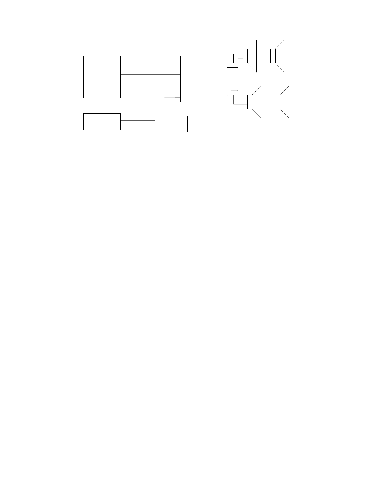
Electronic
Key System
C. O. Line
Port
Page Port
Contact
Closure
Music
Source
FIGURE 1 - SIMPLIFIED BLOCK DIAGRAM OF A TYPICAL INSTALLATION
(Arrangement 1)
SYSTEM DESIGN
Telephone System Requirements
The V-9937 is designed to work with telephone
system page ports, which provide an audio pair (8
to 600 Ohms) and a dry contact closure for
control. This will be referred to as Arrangement
1.
The V-9937 may also be used with page ports (8
to 600 Ohms) that do not have control leads, with
two feature limitations:
) If background music is desired, the telephone
1
system must be capable of providing the
switching instead of the V-9937;
The AGC and pop suppression circuitry will not
2)
be enabled on a standard page (they will still
work on page override). This will be referred to
as Arrangement 2.
NOTE: Refer to the Installation section for
Arrangement 1 and 2 connecting information.
Equipment
A complete one zone one-way page system using
the V-9937 will be made up of the following:
•
Telephone system page card (if page ports
are not standard)
• V-9937 page port adapter
• Valcom one-way amplified speaker
assemblies (or existing high power amplifier
and speakers)
• -24VDC power supply
Optional (depending on individual job
requirements):
• Music source
• V-9942 Tone Module
.
V-9937
Input 1
Input 2
Control
Input 3
Power
Supply
Output 1
Pwr
One-W ay Amplified
Speaker Assemblies
Output 2
Pwr
Page
+
Music
Page
Only
INSTALLATION
Instructions
The following sections contain step by step
instructions for wiring the V-9937. Each
instruction is preceded by a line. Place a check on
the appropriate line as the instruction is
completed. The instructions also include tests
along the way to verify connections have been
made correctly. If these steps are followed
exactly, installation of your Valcom system will go
smoothly and quickly. If the results of a test do not
correspond with what is shown, do not proceed
until the problem has been corrected.
NOTE: The telephone system referred to in
this manual is the customer premise
equipment such as an electronic key system, a
PABX or a dedicated single line telephone (s).
The V-9937 is not intended for direct or indirect
connection to the public telephone network or
to PABX analog station ports. When used with
a customer premise telephone system such as
a key system or PABX system, these units are
interfaced to the system via a fully protected
page port or system central office port, which
is a fully protected interface device. Also, the
host system must be configured to disallow
central office trunk conferencing in order to
prevent indirect connection to the public
network.
2
Page 3
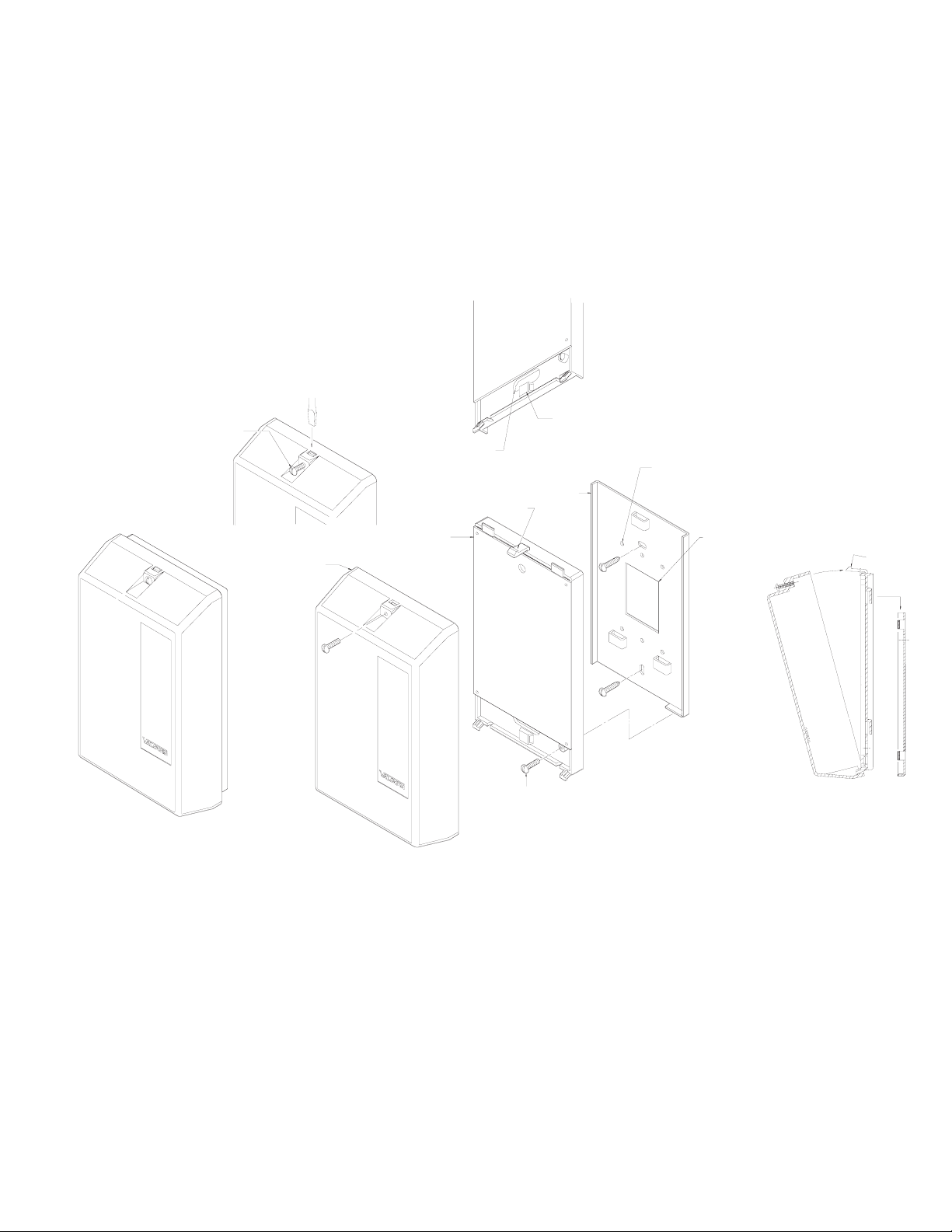
Mounting
Remove the metal mounting plate from the rear of the V-9937 enclosure. Using two #6 ¾ inch wood screws,
mount the plate in a vacant space on the backboard with the telephone system common equipment. Both
mounting holes must be utilized to insure secure mounting of the unit. Provisions for mounting to a
single or double gang junction box are provided. See Figure 2
Open the V-9937 enclosure to allow access to connections and option switches. Slide the rear of the unit
(contains the board) onto the mounting plate. Lock enclosure to mounting plate with screw provided. Make
connections. Replace cover and lock in place with #6 ½ inch screws provided.
TO REMOVE COVER
LOOSEN SCREW,
THEN ACTIVATE LATCH
PLASTIC
COVER
WIREWAY OPENING
TO WALL PLATE AND
JUNCTION BOX
CIRCUIT BOARD
HOUSING ASSEMBLY
SNAP LATCH
WIRE TIE LOOP
WIRE TIE USED TO BUNDLE WIRES
ENTERING AND LEAVING TERMINAL AREA
METAL WALL
MOUNTING
PLATE
.155 DIA. HOLES FOR MOUNTING TO
SINGLE OR DOUBLE GANG JUNCTION BOX
HOLE PATTERN MATCHES BOTH EURO
AND US JUNCTION BOXES
1.5 x 2 WIRE ACCESS OPENING
TO JUNCTION BOX
BRACKET
LOCKING
SCREW
FIGURE 2
MOUNTING
EXPLODED VIEW
SNAP LATCH
FOR COVER
3
Page 4

Connecting Arrangements
There are two possible ways this equipment may
be used as described in the following paragraphs.
Place a check by the arrangement being used in
this installation.
___ 1. Arrangement 1:
Access Method: Electronic Key or PABX
page port with "page enable" dry relay
contact.
Override Access: Electronic Key C. O.
button or PABX loop start trunk.
Music: Input background music to V-
9937.
Additional Features: Pop suppression
and AGC on page and override. Two
outputs, one with music and one without.
Tone signaling option.
___ 2. Arrangement 2:
Access Method: Electronic Key or PABX
page port (no control leads required).
Override Access: Electronic Key C .O.
button or PABX loop start trunk.
Music: Background music may be
provided if the telephone system provides
the needed inputs and switching.
Additional Features: Pop suppression
and AGC on override only. Tone signaling
option
.
LOCATION AND NUMBERING OF CONNECTION BLOCK
GROUND OUT14-24 OUTPUT
15
28
2930
GROUND IN
-24 VDC IN
15
30
FIGURE 3
SINGLE TONE
WARBLE TONE
TIP OUT 2
-24 OUT
-24 OUT
TIP OUT 1
2527 26
9
8765
24
RING OUT 2
GROUND OUT
FIGURE 4
RING OUT 1
GROUND OUT
202223 21
12 1011
13
SINGLE TONE
WARBLE TONE
CONNECTING BLOCK POINTS
1
16
19
CTRL GND IN
TIP INPUT 3
4
321
CTRL GND OUTRING INPUT 3
RING INPUT 2
TIP INPUT 1
TIP INPUT 2
1618 17
RING INPUT 1
Wiring (Arrangements 1 and 2)
Refer to Figure 2 for location and numbering of
connection block and Figure 3 for connecting
block pin outs.
___ 1. Unplug power supply.
___ 2. Connect -24VDC "B" battery (may be
referred to as "-" or "signal battery") from
power supply to pin 30 on V-9937.
___ 3. Connect 24VDC Ground ("B" ground, "+"
or "signal ground") from power supply to
pin 29.
___ 4. Connect 24VDC Ground from power
supply to telephone system Ground.
___ 5. Power test:
(a) Plug in power supply.
(b) If power reversal LED is lit:
(1) Unplug power supply;
(2) Reverse connections on pins 29
and 30;
(3) Go to step 6.
___ 6. Unplug power supply.
NOTE: Power supply pins 6, 21, 8 and 23 for
external speaker power are provided as a
convenience. When using large numbers of
speakers with the V-9937, the speakers should
be connected directly to their respective power
source.
Wiring Arrangement 1
Page Access:
___ a. Connect V-9937 pin 2 to page port Tip.
___ b. Connect pin 17 to page port Ring.
Override Access:
___ a. Connect V-9937 pin 1 to override trunk (or
override line key) Tip.
___ b. Connect pin 16 to override Ring.
Control Leads:
___ a. Connect V-9937 pin 3 to one side of page
port dry contact closure.
___ b. Connect pin 18 to the other side of the dry
contact closure.
Music Input:
___ a. Connect pin 4 of the V-9937 to one side of
the music source output.
___ b. Connect pin 19 to the other side of the
music output.
NOTE: Use a low level music source such as a
tuner. DO NOT connect the output of a high
power amplifier to the Valcom unit.
4
Page 5

Speaker Connections:
Speakers receiving background music:
___ a. Connect pin 7 of V-9937 to Tip of the
amplified speaker assembly.
___ b. Connect pin 22 to Ring of the Speaker.
___ c. Connect pin 6 to -24VDC terminal of
speaker (white lead if using horns).
___ d. Connect pin 21 to GND terminal of
speaker (black lead of horns).
Speakers not receiving background music:
___ a. Connect pin 9 of the V-9937 to Tip of the
amplified speaker assembly.
___ b. Connect pin 24 to Ring of the speaker.
___ c. Connect pin 8 to -24VDC terminal of
speaker (white lead if using horns).
___ d. Connect pin 23 to GND terminal of
speaker (black lead of horns).
Go to the Volume Adjustment section.
Wiring Arrangement 2
Page Access:
___ a. Connect V-9937 pin 4 to page port Tip.
___ b. Connect pin 19 to page port Ring.
Override Access:
___ a. Connect V-9937 pin 1 to override trunk (or
override line key) Tip.
___ b. Connect pin 16 to override Ring.
Music Input:
NOTE: Background music may only be
connected if the telephone system provides
the appropriate inputs.
___ a. Connect music source to telephone
system following phone system installation
instructions.
Speaker Connections:
___ a. Connect pin 7 of V-9937 to Tip of the
amplified speaker assembly.
___ b. Connect pin 22 to Ring of the speaker.
___ c. Connect pin 6 to -24VDC terminal of
speaker (white lead if using horns).
___ d. Connect pin 21 to GND terminal of
speaker (black lead of horns).
NOTE: Set speaker volume controls at
approximately 1/2 volume during installation.
Volume Adjustment and Test
Refer to Figure 4 for location of volume controls.
Test the system and adjust the controls as follows:
NOTE: For proper operation, the controls
must be adjusted in the order specified.
___ 1. Set the "Output 1" and the "Output 2"
controls to approximately 1/2 volume. Set
the "Input 3" control fully
counterclockwise.
___ 2. Connect a lineman's test set to the V-9937
pins 1 and 16.
___ a. Go "off hook" and speak. Paging should
be heard through the speakers.
___ b. If paging is not heard, recheck
connection. Refer to the Troubleshooting
Chart.
___ c. While speaking, adjust the individual
speaker volume controls to the desired
level.
___ 3. If using wiring Arrangement 1 with
background music, the "Input 3" control
may be adjusted to set the desired level of
background music.
___ 4. If using wiring Arrangement 2, access the
page port through the Telephone System
and use the "Input 3" control to set the
proper system page level.
NOTE: The "Output 1" and the "Output 2"
controls may be used as master controls to
change the system volume.
Tone Module Option
The V-9942, Tone Module Card, may be added to
provide two types of electronic tone signaling over
the paging. An installation may use one or both
types of signaling. Check the type of signaling
being used:
___ 1. Interrupted warble tone (one second tone
every four seconds).
___ 2. A single frequency non-interrupted tone.
The tones are activated by connecting the
appropriate pins together (typically through a dry
contact closure).
The single tone will override the warble tone if
both are accessed at the same time. If a page is
in progress, the tone will be mixed with the page.
VOLUME:
OUTPUT 2
OUTPUT 1
POWER
REVERSAL
LED
LOCATIONS OF SWITCHES AND CONTROLS
TONE SELECT:
OUTPUT 2 OUTPUT 1
ON OFF ON OFF
SW2 SW1
V-9937
V-9942
(Optional)
V-9942
Connector
15 1
30 16
FIGURE 5
INPUT 3
TONE
LEVEL
CONTROL
INPUT 3
LEVEL
ADJUST
5
Page 6

Installation:
___ 1. Disconnect power from V-9937.
___ 2. Plug V-9942, Tone Module, into jack
provided in V-9937.
___ 3. Warble Tone
___ a. Connect pin 11 of V-9937 to one side of
dry contact closure being used to control
the warble tone.
___ b. Connect pin 26 to the other side of the
closure.
___ 4. Single Tone
___ a. Connect pin 12 of the V-9937 to one side
of dry contact closure being used to
control the single tone.
___ b. Connect pin 27 to the other side of the
closure.
___ 5. Referring to Figure 4, set the volume
control on the V-9942 to approximately
1/2.
___ 6. Set the tone select switches (Figure 4) to
determine which outputs will receive tones
(OFF: No tones; ON: Tones).
___ 7. Reapply power to the unit.
___ 8. Testing the Tones
___ a. IMPORTANT: Verify volume controls
have been adjusted.
___ b. Momentarily connect between pins 11 and
26 of the V-9937. A warble tone should
be heard from any speakers connected to
outputs that have the tone select switch
set ON.
___ c. Momentarily connect between pins 12 and
27. A single frequency tone should be
heard from any speakers connected to
outputs that have the tone select switch
on.
___ d. If proper results are not obtained in (b)
and (c), then remove power from the V-
9937; return to the beginning of this
Section and verify all connections.
___ 9. While shorting pins 12 and 27, adjust the
V-9942 volume control to the desired
level.
OPERATION
Circuit Description
The V-9937, One Zone Page Port Adapter, will
interface to most E-KEY or PABX page ports to
provide a single zone of one-way paging with
automatic gain control, pop suppression and
background music cut off. The V-9937 has 3
inputs:
Input 1: provides talk battery and contains loop
detection circuitry. It is to be accessed from a C.
O. line button on E-Key Systems or a loop trunk
port on PABX's. Signals on this input will go
through the AGC and pop suppression circuits.
Accessing this port will override inputs 2 and 3.
Input 2: is transformer coupled to the V-9937.
Ground must be applied to pin 3 for this input to
operate (provided from pin 18 through the
telephone system contact closure). When ground
is applied to pin 3, input 3 will be overridden.
Audio on this input will go through the AGC and
pop suppression circuits. Typically this input will
connect to an 8 or 600 Ohm page port.
Input 3: is transformer coupled to the V-9937 and
is active any time inputs 1 and 2 are not in use.
This input is not affected by AGC or pop
suppression and is typically used as a music input.
The output of the V-9937 is designed to drive
Valcom One-Way Amplified Speaker Assemblies.
Two outputs are provided. Output 1 provides
paging and background music with automatic
music cutoff during a page. Output 2 provides
paging without music for areas where music is not
desired.
TECHNICAL ASSISTANCE
When trouble is reported, verify that power is
being supplied to the unit and there are no broken
connections. Check voltages for proper polarity
on the cross connect block.
Table 1 identifies symptoms of some possible
problems with solutions. If your problem is listed,
perform the actions indicated. A lineman's test
set, several clip leads, and a VOM may be
necessary to effectively troubleshoot the unit.
If the trouble can not be located, continue to
troubleshoot by substituting a spare unit for the
suspected unit.
Assistance in troubleshooting is available from the
factory. When calling, you should have a VOM
and a test set available and call from the job site.
Call (540) 563-2000 press 1 for Technical Support
or visit our website at http://www.valcom.com.
Valcom equipment is not field repairable. Valcom,
Inc. maintains service facilities in Roanoke, VA.
Should repairs be necessary, attach a tag to the
unit clearly stating your company name, address,
phone number, contact person and the nature of
the problem. Send the unit to:
Valcom, Inc.
Repair and Return Dept.
5614 Hollins Road
Roanoke, VA 24019-5056
6
Page 7

Table 1 - Troubleshooting Chart
Symptom
1. No output
2. No output when using Input 1
3. No output when using Input 2
4. No tone signaling
VALCOM LIMITED WARRANTY
Valcom, Inc. warrants its products to be free from defects in materials and workmanship under conditions of normal use and service
for a period of one year from the date of shipment. The obligation under this warranty shall be limited to the replacement, repair or
refund of any such defective device within the warranty period, provided that:
1. inspection by Valcom, Inc. indicates the validity of the claim;
2. the defect is not the result of damage, misuse or negligence after the original shipment;
3. the product has not been altered in any way or repaired by others and that factory sealed units are unopened (a service
charge plus parts and labor will be applied to units defaced or physically damaged);
4. freight charges for the return of products to Valcom are prepaid;
5. all units ‘out of warranty’ are subject to a service charge. The service charge will cover minor repairs (major repairs will
be subject to additional charges for parts and labor).
This warranty is in lieu of and excludes all other warranties, expressed or implied, and in no event shall Valcom, Inc. be
liable for any anticipated profits, consequential damages, loss of time or other losses incurred by the buyer in connection
with the purchase, operation or use of the product.
This warranty specifically excludes damage incurred in shipment. In the event a product is received in damaged condition, the
carrier should be notified immediately. Claims for such damage should be filed with the carrier involved in accordance with the
F.O.B. point.
Solution
A. Verify -24VDC present on pins 29 and 30. Power reversal
LED
should not be on.
B. Verify music present on pins 4 and 19.
C. Verify proper polarity on power leads to speakers.
D. Verify volume control settings.
A. Test unit by placing telephone test set on pins 1 and 16, going
off
hook and paging.
A. Verify ground is present on pin 3 when accessing page.
B. Verify audio is present on pins 2 and 17 when paging.
A. Verify V-9942 plugged in correctly.
B. If V-9937 is not working correctly in all other respects, then
start
at troubleshooting chart Step 1.
C. Verify connections on pins 11 and 26 and/or 12 and 27. Test
by
momentarily shorting these pairs and listening for tones at
speakers.
Headquarters:
Valcom, Inc.
5614 Hollins Road
Roanoke, VA 24019-5056
Phone: (540) 563-2000
FAX: (540) 362-9800
7
Page 8

V-9937 CONNECTING BLOCK
151413121110987654321
30 29 28 27 26 25 24 23 22 21 20 19 18 17 16
-24VDC
POWER
SUPPLY
+-
PAGE
ONLY
VALCOM
ONE-WAY
AMPLIFIED
SPEAKER
ASSEMBLIES
PAGE
PLUS
MUSIC
MULTIPLE TO
ALL SPEAKERS
TIP
RING
-24
GND
MULTIPLE TO
ALL SPEAKERS
TIP
RING
-24
GND
NOTE: ALL CONNECTIONS NOT MARKED
OPTIONAL MUST BE COMPLETED
PABX OR ELECTRONIC
KEY SYSTEM
C. O. LINE BUTTON
R
(OPTIONAL, FOR
T
PAGE OVERRIDE)
R
PAGE PORT
T
DRY CONTACT CLOSURE
MUSIC SOURCE
(OPTIONAL)
R
T
FIGURE 5 - WIRING CONNECTIONS FOR ARRANGEMENT 1
VALCOM
ONE-WAY
AMPLIFIED
SPEAKER
ASSEMBLIES
V-9937 CONNECTING BLOCK
151413121110987654321
30 29 28 27 26 25 24 23 22 21 20 19 18 17 16
+-
-24VDC
POWER
SUPPLY
MULTIPLE TO
ALL SPEAKERS
TIP
RING
-24
GND
NOTE: ALL CONNECTIONS NOT MARKED
OPTIONAL MUST BE COMPLETED
PABX OR ELECTRONIC
KEY SYSTEM
C. O. LINE BUTTON
R
(OPTIONAL, FOR
T
PAGE OVERRIDE)
R
PAGE PORT
T
MUSIC INPUT
(IF AVAILABLE)
MUSIC SOURCE
(OPTIONAL)
FIGURE 6 - WIRING CONNECTIONS FOR ARRANGEMENT 2
8
 Loading...