

Page 1
V-9932
NOISE SENSING VOLUME CONTROL
GENERAL
The V-9932 is designed to electronically adjust the
level of a page by monitoring ambient noise levels in
an area of a building.
These instructions contain the specifications and
information necessary to install, operate, and maintain
the V-9932 Noise Sensing Volume Control.
SPECIFICATIONS
Purpose
The V-9932 provides automatic paging level
adjustments in areas where ambient noise levels are
continuously changing.
VSP-V-9932
Issue 9
Application
• Valcom one-way paging systems
Features
• Solid-state design
• Low power requirements
• Operates on key system voltages
• Self-contained se nsing device
Capacity
Each V-9932 will control up to 150 Valcom one-way
amplified speaker assemblies in a single zone.
Multiple V-9932 units can be used within the same
zone.
Additional Materials Required
At the time of installation, the installer should provide
the following materials:
• 24VDC power supply (if existing supply is
inadequate)
• "D" type station wire
Dimensions/Weight
The V-9932 is designed to be wall mounted.
• 7.3"H x 4.7”W x 2.1"D
(18.54cm H x 11.94cm W x 5.33cm D)
• 0.9 lbs. (.41kg)
Power Requirements
The V-9932 requires -24VDC Signal Battery.
Range -20 to -28VDC "B" Battery
Idle 50 mA
Operating 100 mA
Nominal Specifications
Automatic Level Adjustment Range -10dB to 30dB
Quench Threshold -23dBm nominal
Power Output -10dBm
Frequency Response 80-10KHz +3dB
Input Impedance 600 ohms
Output Impedance 8 ohms
Operating Temperature 0 to 50 degrees C
Power Requirements -24VDC signal battery
Monitor Reset 5 sec.
1 947932
Page 2
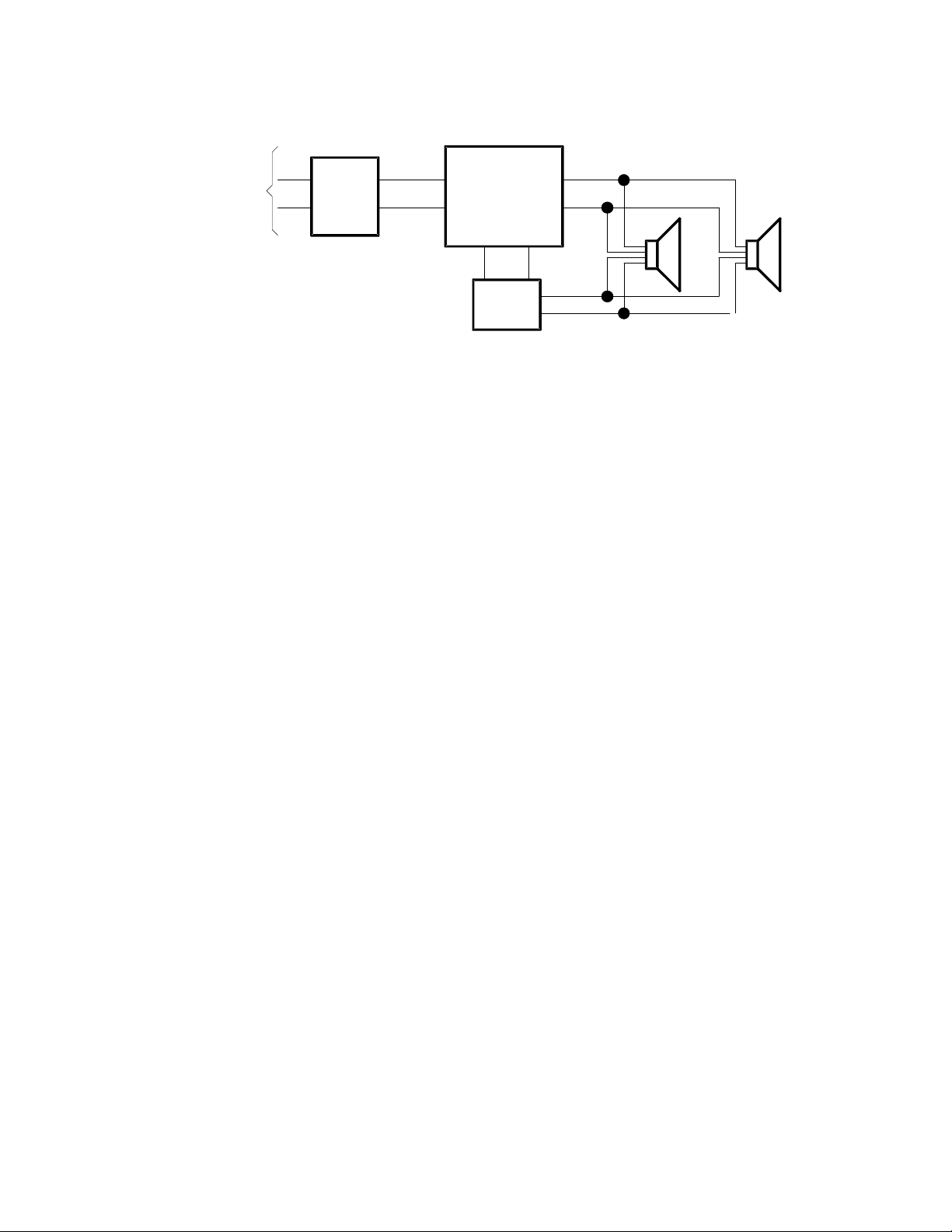
To
Telephone
System
T
Valcom
Page
R
Control
Unit
Zone A
T
IN
R
V-9932
-24V GND
Power
Supply
T
OUT
R
Maximum 150 Amplified
One-Way Speaker Assemblies
Figure 1 - Simplified Block Diagram of Connections
INSTALLATION
These instructions cover only the installation
procedure of the Valcom V-9932. Please consult
applicable instructions for control equipment or any
other equip ment used.
Precautions
All precautions have been taken at the factory to
insure that the equipment functions properly. Please
observe the following precautions or the equipment
may be damaged and the warranty voided.
a. Unplug the power supply before connecting any
wires or cables to the control unit connecting
block. With power on, accidental bridging of
two terminals with a wiring tool may damage
electronic circuits.
b. Do not use a lamp tester to check signals. Use a
voltmeter. A lamp tester, when first applied is a
short circuit to electronic circuits.
c. Do not ap ply power to the control unit until all
connections have been double-checked.
NOTE: The V-9932 cannot be used to control
music.
Mounting
a. Locate a space on the wall central to the noise
producing equipment.
b. Carefully unpack the unit from the carton and
inspect.
c. Unsnap cover from base and mount base to wall
using pan head screws.
b. Connect the input of amplified speaker to T and
R output of V-9932.
c. Connect power supply -24VDC and ground to
-24 and GND terminals on V-9932.
Set-Up and Adjustment
a. Complete all connections to page control unit,
V-9932, one-way amplified speakers, and power
supply (refer to applicable instructions).
b. With background noise at its lowest level, access
page system and adjust level controls on page
control and speakers for proper sound level.
c. Turn on all noise producing equipment for
maximum background noise l evel.
d. Access page and test.
NOTE: The V-9932 microphone gain is factory
adjusted. This adjustment is correct for most
applications.
e. I f page volume with maximum background i s t oo
high, turn microphone gain control counter
clockwise in small increments and test.
Important: Wait at least 10 seconds after
adjusting microphone gain before accessing
page and testing.
f. If page volume with maximum background noise
is too low, turn microphone gain control
clockwise in small increments and test.
Important: Wait at least 10 seconds after
adjusting microphone gain before accessing
page and testing. Do not adjust microphone
gain beyond the point where the LED lights.
g. Installation and set-up now complete.
Connections
Refer to Figure 2 while performing the following:
a. Connect the page control unit speaker output to T
and R input of V-9932.
2 947932
Page 3

Do Not Adjust
Microphone Gain
TECHNICAL ASSISTANCE
When trouble is reported, verify that power is being
supplied to the unit and there are no broken
connections. Check voltages for proper polarity on
terminals.
Do Not Adjust
V-9932
T R -24V GND T R
Input
(from page
control)
Output (To oneway amplif i ed
speakers)
LED
Figure 2
OPERATION
The V-9932 Noise Sensing Volume Control
continuously monitors t he surrounding ar ea noise by
utilizing a built-in microphone. When a page is
made, the V-9932 electronically locks onto the last
area noise sample. A -23dBm signal or higher is
required on the input before the V-9932 will activate
and lock. Once activated, the amplifier is
automatically set to the proper gain level for the
amount of background noise. The amplifier will
remain locked at that gain level for the duration of the
page. After the page is made there is a 5 second
delay before the V-9932 starts monitoring the area
noise levels. Refer to Figure 3 for a simplified
schematic of the V-9932.
Table 1 identifies symptoms of some possible
problems with solutions. If a spare unit is available,
continue to troubleshoot by substituting the spare unit
for the suspected defective unit.
Assistance in troubleshooting is available from the
factory. When calling, you should have a VOM and a
telephone test set available and be calling from the
job site. Call (540) 427-3900 and ask for Technical
Support, or call (540) 427-6000 for Valcom 24-hour
Automated Support or visit our website at
http://www.valcom.com.
The V-9932 is not field repairable. Valcom
equipment contains no user serviceable parts
inside. Valcom, Inc. maintains service facilities in
Roanoke, VA. Should repairs be necessary, attach a
tag to the unit clearly stating your company name,
address, phone number, contact person, and the
nature of the problem. Send the unit to:
Valcom, Inc.
Repair and Return Dept.
5614 Hollins Road
Roanoke, VA 24019-5056
TABLE 1 - TROUBLESHOOTING CHART
SYMPTOM POSSIBLE SOLUTION
No page 1) Check -24V DC and Ground to unit and to one-way speakers.
Volume incorrect with no bac kground noise 1) With no back ground noi se, access page and adjust vol ume at page
Can't hear with full background noise
Too loud with full background noise 1) Turn microphone gain control counter clockwise in smal l i ncrements.
Loud squeal when paging 1) Relocate phone or speaker.
2) Check * f or audi o at tip and ring input to V-9932.
3) Check * f or audi o at tip and ring output from V-9932.
control unit or at one-way amplifi ed speakers.
1) Turn mi crophone gain control clockwise in small increment s.
seconds before accessing page to test.
Wait 10 seconds before accessing page and testing.
2) Install noise cancel i ng transmitter on phone.
3) Readjust page level.
Wait 20
*Use lineman's test set to check for audio.
3 947932
Page 4

Valcom, Inc. warrants i ts products to be free from defects in mat erials and workmanship under conditi ons of normal use and
VALCOM LIMITED WARRANTY
service for a period of one year from the date of shipment. The obl i gation under this warranty shall be lim i ted to the replacement,
repair or refund of any such defecti ve device within the warranty period, provided that:
1. inspection by Valcom, Inc. indicat es the validity of the claim,
2. the defect is not the res ul t of damage, mis use, or negligence after the original shipment.
3. the product has not been altered in any way or repaired by others and that factory sealed units are unopened (A service
4. freight charges for the return of products to Valcom are prepai d,
5. all units ‘out of warranty’ are subject to a service c harge. The service charge will cover minor repairs (Major repairs will
This warranty is in lieu of and excludes all other warranties, expressed or implied, and in no event shal l Valcom, Inc. be
liable for any anticipated profits, consequential damages, loss of time or other losses incurred by the buyer in connection
with the purchase, operation, or use of the product.
This warranty specifically excludes damage incurred in shipment . In the event a product is rec ei ved in damaged condition, the
carrier should be notified immediately. Claims for such damage s houl d be filed with the carrier involved in accordance with the
F.O.B. point.
charge plus parts and labor will be applied to units defaced or physic ally damaged),
be subject to additional c harges for parts and labor).
Headquarters: In Canada
Valcom, Inc. CMX Corporation
1111 Industry Avenue 35 Van Kirk Drive #11 and 12
Roanoke, VA 24013 Brampton, Ontario L7A1A5
Phone: (540) 427-3900 Phone: (905) 456-1072
FAX: (540) 427-3517 FAX: (905) 456-2269
MICROPHONE
T
INPUT
R
BG
BB
SIMPLIFIED SCHEMATIC
MICROPHONE GAIN
LEVEL SENSE
CIRCUIT
PAGE SENSE
CIRCUIT
REGULATOR
FIGURE 3
CONTROL
CIRCUIT
AMPLIFIER
T
OUTPUT
R
-12
-24
4 947932
 Loading...