

Page 1
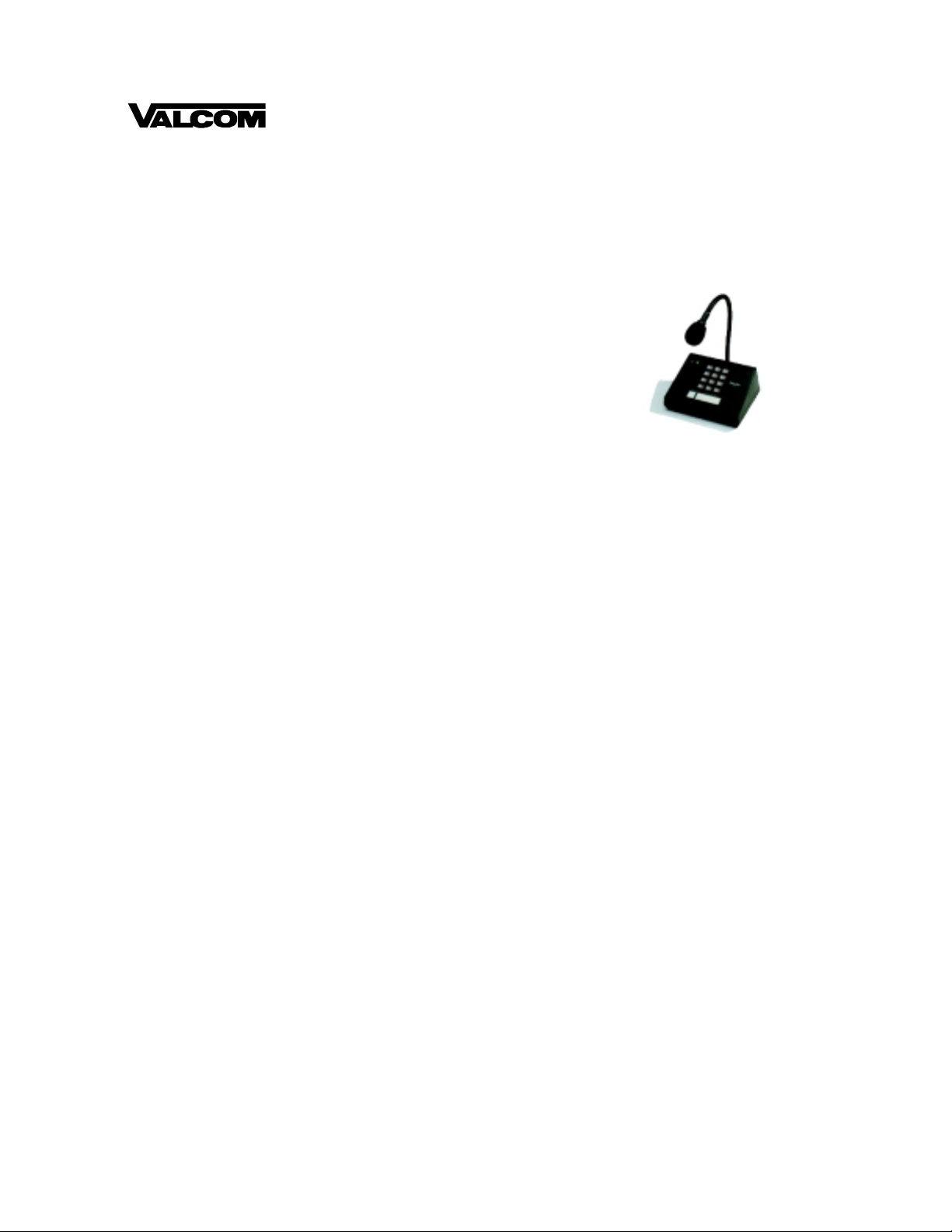
PagePac
®
by
MULTI-ZONE MICROPHONE
V-5335405
INTRODUCTION
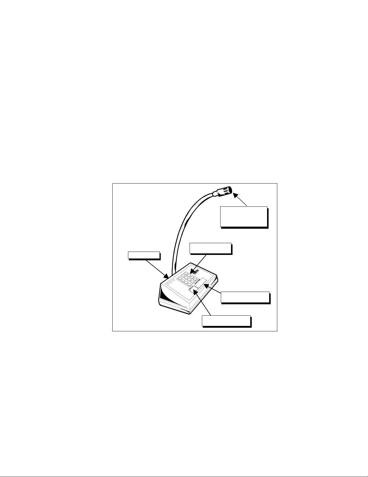
Your high fidelity desk microphone provides high
quality, low noise single and multi-zone paging
capability to existi ng paging products. A cardioid
electret element suppresses background noise,
and is housed on the end of a flexible tube. You
can page through a momentary push-button for
short pages, or make a long page with a lock-on
button. Front panel LEDs indicate paging status
(see Figure 1).
The back panel is shown in Figure 2. An attached
wall socket transformer provid es power to the unit.
Connections for tip and ring, busy buss, and dry
contact closure are made at a compression scr ew
terminal block. You can adjust the output volume
level by screwdriver. The multi-zone model has a
switch for selecting dedicated single zone paging.
SPECIFICATIONS
FEATURES
• DTMF Pad for Multi-Zone Access
• Can be Switched to Dedicated Single-Zone
• Momentary Push or Lock-On Page Button
• Front Panel LEDs
Power Requirements
• 120 VAC, 60 Hz
Dimensions/Weight
• Base: 7”W x 3”H x 5”D
(17.78cm x 7.62cm x 12.7cm)
Gooseneck: 14”H (35.56cm)
• 2.50 lbs (1.13 kg)
OPERATION
To make a short page, press and hold the larger,
momentary contact push- button. To make a longer
page, press the smaller locking push-button; when
the page is over, press this push-button again to
Issue 1
deactivate. On the multi-zone model, use the
DTMF pad to select zone addresses or implement
paging features; Refer to your Page Controller
Manual for zone options.
The three LEDs on the front panel show paging
status. A flashing yellow LED indicates a long
term page. The red LED indicates a busy condition on the system. The green LED indicates that
the microphone is on and ready to initiate a page
(even when the unit is paging).
The volume can be adjusted by using the screwdriver-accessible output level at the back panel
(see Figure 2).
INSTALLATION
The microphone has rubber feet for placing
directly on a desktop. Connect the transformer to
a standard 120 VAC 60 Hz wall socket. Figure 3
shows the wiring connections at the microphone
terminal block. Multiple microphones may be
wired to an amplifier in either a st ar or daisy chai n
configuration, as shown in Figure 4. Choose the
configuration that minim izes the length of wiring
runs.
Figure 5 shows the wiring diagram for connecting
microphones to a PagePac D-Series Ampli Center
amplifier. An additional terminal block is recommended with the star configuration for connecting
the various incoming wires at the amplifier end.
1947189
Page 2
Note: The shielding for the wires should NOT be
connected to the GND screw at any microphone
in the star configuration.
Note: The Shield should remain conti nuous to the
end of the wire run and should only be grounded
at the amplifier.
TECHNICAL ASSISTANCE
When calling, have a VOM and a telephone test
set available and call from the job site. Call (540)
427-3900 and ask for PagePac Technical Support, or call (540) 427-6000 for Valcom 24-hour
Automated Support or visit our websites at
http://www.pagepac.com and www.val com.com.
Figure 6 shows the wiring diagram for connecting
microphones to a Paging Controller Unit.
LED INDICATORS
Should repairs be necessary, attach a tag to the
unit clearly stating comp any name, address,
phone number , contact person, and the nature of
the problem. Send the unit to:
Valcom, Inc.
PagePac
®
Repair Dept.
5614 Hollins Road
Roanoke, VA 24019-5056
CARDIOID ELECTRET
CONDENSER ELEMENT
WITH HIGH SUPPRESSION
OF BACKGROUND NOISE
TOUCHTONE PAD FOR
MULTI-ZONE ACESS
MOMENTARY PUSHBUTTON
FOR SHORT PAGES
LOCKING PUSHBUTTON
FOR LONG PAGES
Figure 1. Multi-Zone Microphone Features
2947189
Page 3

SCREWDRIVER-ACCESSIBLE
VOLUME CONTROL
SWITCH FOR DEDICATED
SINGLE-ZONE PAGING
Output
COMPRESSION SCREW
TERMINAL BLOCK
Normally Open
Busy Buss for Multiple Microphones
Contacts
Figure 2. Back Panel Controls and Connectors
Enlarged View
GND
Mic
Level
Control
Single Zone
Page
V-5335405
Ref. No. 22700-003
Valcom, Inc.
Roanoke, VA 24019-5056
ON
OFF
CABLE CONNECTED TO WALL SOCKET
TRANSFORMER PROVIDES 12 VAC
OUTPUT
BUSY
BUSS
CONTACT
CLOSURE
Figure 3. Wiring Connections on Microphone Terminal Block
3947189
Page 4

STAR WIRING
A
AMPLIFIER
SHIELDED WIRE
NO SMALLER THAN
24 AWG UP TO 1000 FT.
DAISY CHAIN WIRING
SHIELDED WIRE
NO SMALLER THAN
24 AWG. NO GREATER
THAN 1000 FT. TOTAL
TO LAST MICHROPHONE
Figure 4. Star or Daisy Chain Wiring Configurations
PAGING IN
70 V OUT MUSIC IN
GROUNDC1RING
+
TIP
-
LEFT
GROUND
GROUND
RIGHT
D SERIES AMPLICENTER
TERMINAL BLOCK
PAGE IN
70 V OUT MUSIC IN
GROUND
C1
RING
+
TIP
-
LEFT
GROUND
GROUND
SHIELD
RIGHT
AMPLIFIER
SHIELD
TERMINAL BLOCK
R66B
STAR WIRING
GND C C - +
(ALL OTHER MICROPHONES ARE ATTACHED
IN A SIMILAR MANNER TO THE TERMINAL BLOCK))
R66B
BUSY +
BUSY -
C C - + BUSY +
GND
C C - + BUSY +
GND
C C - + BUSY +
GND
C C - + BUSY +
GND
DAISY CHAIN WIRING
BUSY -
BUSY -
BUSY -
BUSY -
MIC 1
MIC 2
MIC 3
MIC 4
Figure 5. Typical Connections to a D-Series AmpliCenter
PAGING
CONTROLLER
TERMINAL STRIP
DAISY CHAIN WIRING
(REFER TO FIGURE 5 FOR
TYPICAL STAR WIRING
CONFIGURATION)
0dBm
SHIELD
0dBu N. B .
A
CC- + BUSY +
GND
CC- + BUSY +
GND
CC- + BUSY +
GND
BUSY -
BUSY -
BUSY -
MIC 1
MIC 2
MIC 3
CC- + BUSY +
GND
BUSY -
MIC 4
Figure 6. Typical Connections to Paging Controller Unit
4947189
 Loading...