

Valcom V-5335030-5 Service Manual

PagePac
®
by
RECESSED ROUND CEILING
SPEAKER BACKBOX (V-5335030-5)
Fits back of Recessed Round Ceiling Speaker (V-5330115 & V-5330215).
Complies with all fire codes in air plenum applications.
DIMENSIONS/WEIGHT
• 12.3”Dia. x 4.0”H (31.24cm x 10.16cm)
2.0 lbs. (0.9 kg)
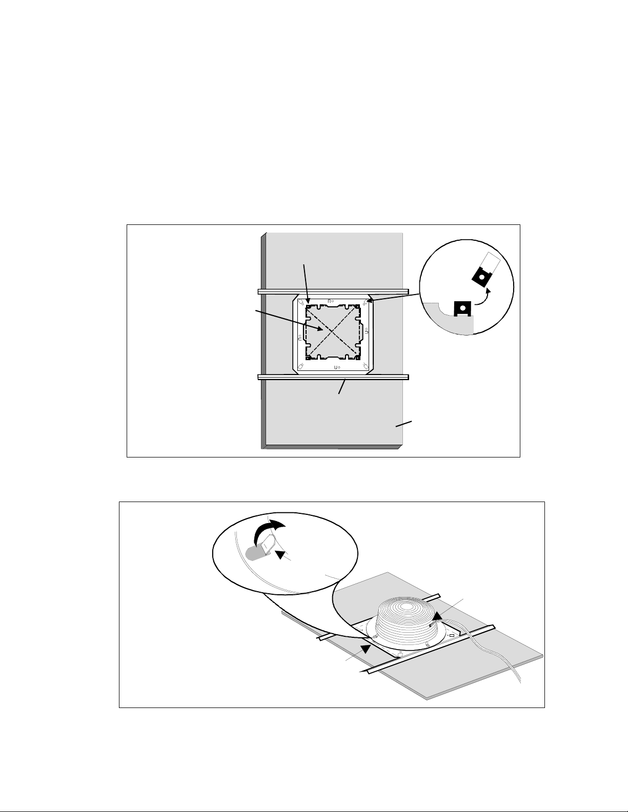
1. Cut an eight and one-half i nch squar e ho le in cei ling til e us ing the su pport bri dge as a templ ate .
2. Bend up the four horseshoe tabs on the support bridge.
3. Position the support bridge on the tile and bend the eight locator tabs into the tile opening.
4. Install the UL listed metallic enclosure entry fitting to the knockout to accommodate plenum
cable or fitting for conduit.
Issue 2
5. Install the enclosure to t he bridge by orienting the four enclosur e slots over the four horseshoe
tabs of the bridge.
6. With pliers, twist the four horseshoe tabs on the br idg e one-half turn, se curi ng the enclosur e to
the bridge. (Note: Four s lots provided on each encl osure to mate with four t wist tabs on support
bridge eliminates need for screws.)
7. Install the speaker/baffle assembly with the four 8-32 screws.
(Screws are provided with the assembly.)
Note: Listed by Underwriters Laboratories, Inc. Category UUMW. Material and construction per-
mits use where ceiling plenum is part of the air handling system.
Note: Compound knockout(s) provided for listed type metallic type fittings for one-half inch and
three-quarter inch plenum rated cable and plenum whip fl ex conduit.
Note: All cable splices and connections to speaker/t ransformer pigtails must be made inside of
listed enclo s ur e .
1947172
TECHNICAL ASSISTANCE
When calling, have a VOM and a telephone test set available and call from the job site.
Call (540) 427-3900 and ask for PagePac Technical Support, or call (540) 427-6000 for Valcom 24hour Automated Support or visit our websites at http://www.pagepac.com and www.valcom.com.
Should repairs be necessary, attach a tag to the unit clearly stating company name, address, phone
number , contact person, and the nature of the problem. Send the unit to:
USING THE BRIDGE SUPPORT AS A TEMPLATE, MARK
A SQUARE OPENING IN THE
CEILING TILE AS SHOWN IN
THE ILLUSTRA TION. REMOVE
THE BRIDGE SUPPORT AND
CUT OUT THE SQUARE WITH
A UTILITY KNIFE.
PagePac
®
Repair Dept.
Valcom, Inc.
5614 Hollins Road
Roanoke, VA 24019-5056
J-NUTS (4)
SPEAKER SUPPORT
BRIDGE
SQUARE SPEAKER
J-NUT PO SITION
(OUTSIDE CUT OUT
ROUND SPEAKER
J-NUT PO SITION
TYPICAL 2' X 4'
CEILING TILE
POSITION)
POSITION THE BACKBOX ONTO THE
BRIDGE SUPPORT AS SHOWN AND
USE HORSESHOE TABS TO SECURE
IT INTO PLACE.
Figure 1
BACKBOX
HORSESHOE TAB
FROM SUPPORT BRIDGE
HORSESHOE TAB (4)
Figure 2
BACKBOX
NOTE: REMOVE THE
FOUR J-NUTS FROM
THE BACKBOX.
BACKBOX KN OCK-OUT HOLE
SPEAKER WIRE
2947172
 Loading...