

Page 1
PagePac
®
by
30 WATT SUSPENDED-RADIAL HORN
(70V) V-5331210
INTRODUCTION
Horn speakers that produce high s ound levels are
capable of covering large noisy areas.
Minimum effective mounting height for a horn is
critical. The Suspended-Radial Horn is used
when 360° sound dispersion pattern is required.
NOTE: Speaker is provided with 10’ mounting
chain. If this is not enough, additional chain must
be acquired. See suggested mounting height for
chain requirements (Figure 2).
SPECIFICATIONS
FEATURES
• High Intelligibility
• Built-in Tr ansformer
• 360° Radial Dispersion
Nominal Specifications
• Frequency Response: 225Hz - 14kHz
• Dispersion: 360°
• 112 dB @ 1W, 1 Meter
• 70 Volt / 30 Watt
Dimensions/Weight
• 13.0"W x 11.8"H (33.0cm x 29.9cm)
10 lbs. (4.5 kg)
Environment
• Temperature: 0 to 40°C (32 to 104°F)
• Humidity: 0 to 85%
Issue 2
INSTALLATION
MOUNTING
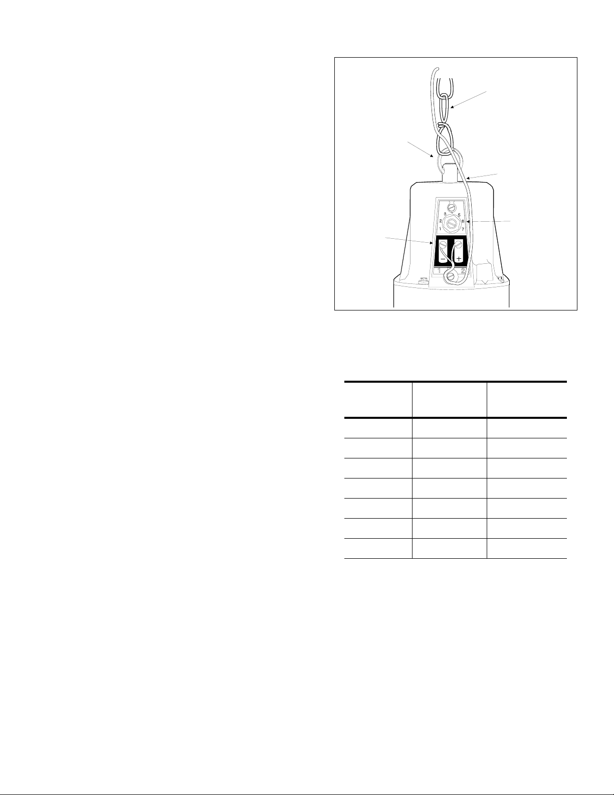
Attach the 10 foot metal chain supplied with the
horn to the post and ring on the horn base (see
Figure 1).
The device used to attach the chain to the ceiling
must withstand a 30 pound pull test, or the weight
specified by local construction or safety codes,
whichever is greater.
WIRE CONNECTIONS
A clear plastic cover protects the horn screw terminals and provides strain relief for the wires.
1. Remove the two screws from the plastic cover.
2. Set volume adjustment to lowest setting.
3. Connect the (+) 70V side of the speaker wire to
terminal 2. Connect the (-) or common side of
the speaker wire to terminal 1 (see Figure 1).
4. Do not replace the plastic cover until final
power adjustments have been made.
1947178
Page 2
FINAL POWER ADJUSTMENTS
Ensure that the speaker is set to its lowest s etting
(this will prevent an excessively loud page when
first used). Conduct test page and increase volume as necessary with a screwdriver. Turn clockwise to increase the volume (see Table 1). Install
the plastic cover.
NOTE: Due to high decibel output, it is not recommended to test paging while working closely with
the horn speaker.
10-FOOT CHAIN
ATTACHMENT RING
SPEAKER CABLE
TECHNICAL ASSISTANCE
When calling, have a VOM and a telephone test
set available and call from the job site. Call (540)
427-3900 and ask for PagePac Technical Support, or call (540) 427-6000 for Valcom 24-hour
Automated Support or visit our websites at
http://www.pagepac.com and www.valcom.com.
Should repairs be necessary, attach a tag to the
unit clearly stating company name, address,
phone number , contact person, and the nature of
the problem. Send the unit to:
Valcom, Inc.
PagePac
5614 Hollins Road
Roanoke, VA 24019-5056
®
Repair Dept.
ERMINALS
FIGURE 1
Table 1: SWITCH SETTINGS
SWITCH
SETTINGS
1 1.80 DO NOT USE
2 3.70 DO NOT USE
3 7.50 0.9
4 15.0 1.80
70V
WATTS
VOLUME LEVEL
CONTROL
(DO NOT FORCE
PAST #7)
25V
WATTS
5 30.0 3.70
6 DO NOT USE 7.5
7 DO NOT USE 15.0
2947178
Page 3

NOISE
LEVEL
IN dB
70 dB
71 dB
72 dB
73 dB
74 dB
75 dB
76 dB
77 dB
78 dB
79 dB
80 dB
81 dB
82 dB
83 dB
84 dB
85 dB
86 dB
87 dB
88 dB
89 dB
90 dB
91 dB
92 dB
93 dB
94 dB
95 dB
96 dB
97 dB
98 dB
99 dB
100 dB
101 dB
102 dB
103 dB
104 dB
105 dB
106 dB
107 dB
108 dB
109 dB
30 WATT RADIAL HORN PROJECTION DISTANCE
WATTAGE SETTINGS FOR 70 VOLT SPK
DISTANCE SHOWN IS THE RADIUS OF CIRCLE OR DISTANCE FROM SPK
SPL-111
1.8 WATT
75**
75**
75**
75**
75**
75**
75**
75**
96
86
75
64
58
53
48
42
37
32
28
26
24
20
18
16
15
13
12
8
7
6
5
SPL-114
3.7 WATT
** USE ATTENUATOR
96
86
75
64
58
53
48
42
37
32
28
26
24
20
18
16
15
13
12
8
7
6
5
12 FT
SPL-117
7.5 WATT
96
86
75
64
58
53
48
42
37
32
28
26
24
20
18
16
15
13
12
8
7
6
5
SPL-120
15 WATT
96
86
75
64
58
53
48
42
37
32
28
26
24
20
18
16
15
13
12
8
7
6
SPL-123
30 WATT
96
86
75
64
58
53
48
42
37
32
28
26
24
20
18
16
15
13
12
8
SUGGESTED
MOUNTING
HEIGHTS
46 FT
30 FT
26 FT
24 FT
18 FT
14 FT
FIGURE 2
3947178
 Loading...