

Page 1
PagePac
®
by
15 WATT HORN (70V) - V-5331200
30 WATT HORN (70V) - V-5331205
INTRODUCTION
The 15 Watt and 30 Watt 70-Volt Horns are suitable for large and/or noisy areas such as, warehouse and manufacturing facilities. Minimum
effective mounting height for a horn is 15 feet, 20
feet is preferable. However, in a system with talkback (hands-free answer back) the speaker may
have to be mounted as low as 8 to 12 feet and set
at a lower power setting.
Speakers must be mounted in locations that provide a clear sound path to the area paged. In
areas with high shelving, more horns may be
needed for adequate coverage. To avoid feedback, do not place telephones or microphones
near horns. Various power outputs can be easily
selected on the speakers, using the rotary power
switch.
SPECIFICATIONS
FEATURES
• Has variable wattage settings
(see Tables 1 and 2 or Figures 3 and 4)
• Works with 25V or 70V systems
Nominal Specifications
• Frequency Response:
15W (275 Hz - 14kHz)
30W (225 Hz - 14kHz)
• Dispersion:
15W (110°) / 30W (100°)
• dB SPL @ 1W, 1 Meter:
15W (111 dB) / 30W (112 dB)
Issue 2
Weight/Dimensions
• 15 Watt Horn (4 lbs./1.8 kg)
8"W x 8"H x 9"D (20.3 x 20.3 x 22.9 cm)
• 30 Watt Horn (6 lbs./2.7 kg)
10"W x 9.5"H x 10.5"D
(25.4 x 24.1 x 26.7cm)
Environment
• Temperature: 0 to 40°C (32 to 104°F)
• Humidity: 0 to 85%
INSTALLATION
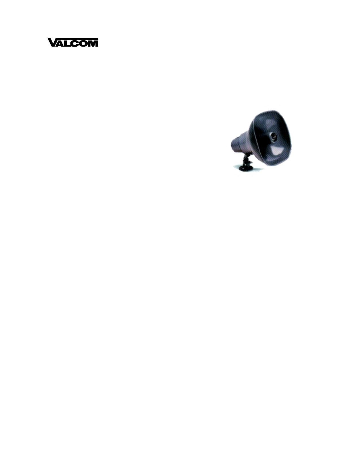
MOUNTING
Loosen the wing nut and remove the tapere d locking pin. Separate the horn from the bracket.
Mount the bracket using appropriate hardware
(not supplied). Reattach the horn to the brac ket.
Position the horn for convenient wiring and hand
tighten the wing nut.
WIRE CONNECTIONS
A clear plastic cover protects the horn screw terminals and provides strain relief for the wires.
Power Requirements
• 15W:25V system: .225W to 1.87W adjustable
70V system: .25W to 15W adjustable
• 30W:25V system: .15W to 3.75W adjustable
70V system: 1.2W to 30W adjustable
1. Remove the two screws from the p lasti c c over.
2. Connect the audio wires to the horn.
3. Connect the (+) 70V speaker wire to
terminal 2 (see Figure 2).
4. Connect the (-) common side speaker wire to
terminal 1 (see Figure 2).
1947167
Page 2
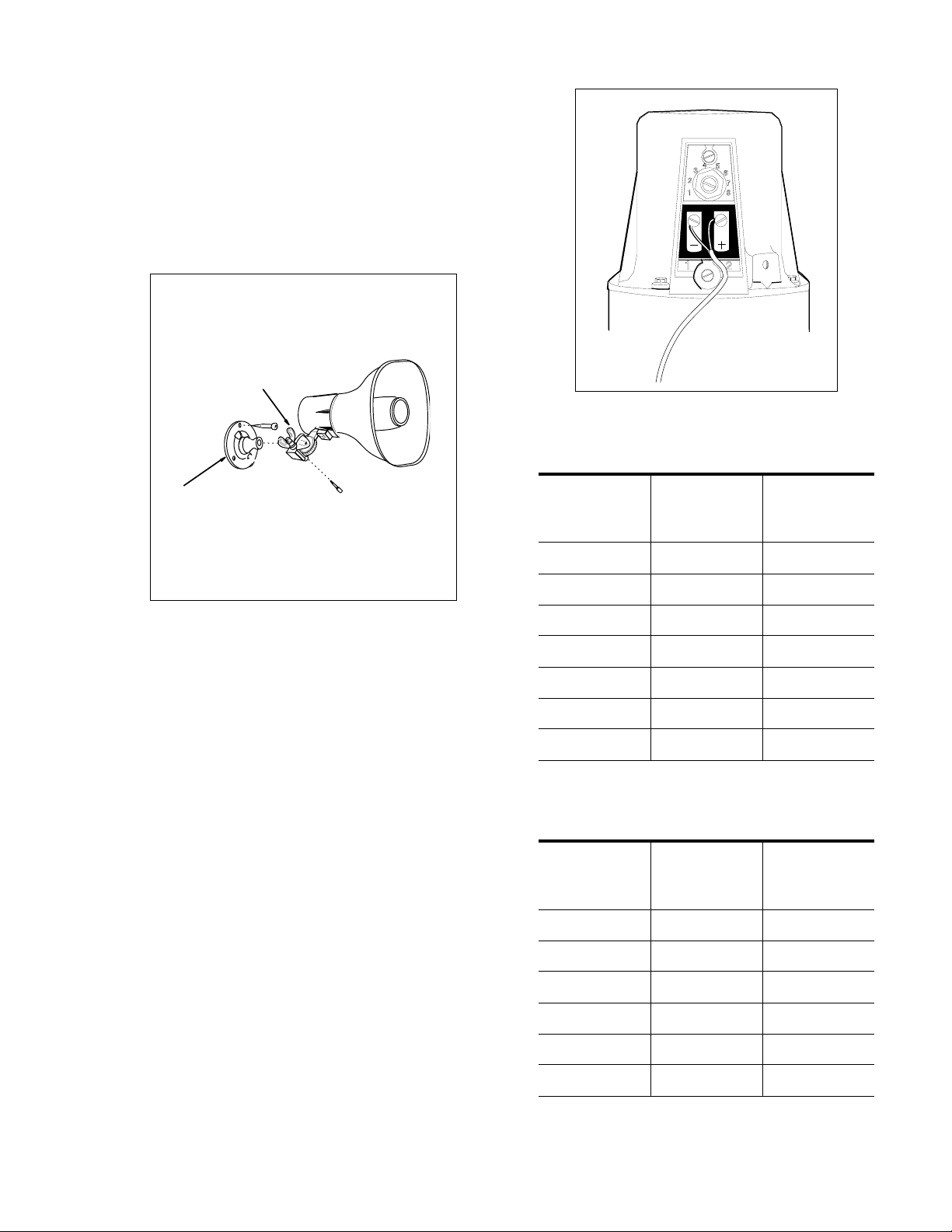
5. Do not replace the plastic cover until final
power adjustments have been made.
FINAL POWER ADJUSTMENTS
While a page is in process, adjust the power tap
setting control with a scr ewdriver. Turn clockwise
to increase the volume (see Figure 2).
NOTE: Protect hearing when working around
horns.
MOUNTING ON FLAT SURFACE
WING NUT
FIGURE 2
Table 1: 15 WATT SETTINGS
MOUNTING
BRACKET
FIGURE 1
TECHNICAL ASSISTANCE
When calling, have a VOM and a telephone test
set available and call from the job site. Call (540)
427-3900 and ask for PagePac Technical Support, or call (540) 427-6000 for Valcom 24-hour
Automated Support or visit our websites at
http://www.pagepac.com and www.valcom.com.
Should repairs be necessary, attach a tag to the
unit clearly stating company name, address,
phone number , contact person, and the nature of
the problem. Send the unit to:
Valcom, Inc.
PagePac
5614 Hollins Road
Roanoke, VA 24019-5056
®
Repair Dept.
70V
SWITCH
SETTING
10.25--
20.50--
30.90-4 1.80 .225
5 3.80 .475
67.50.93
715.01.87
Table 2: 30 WATT SETTINGS
SWITCH
SETTING
1 1.2 .15
2 2.5 .31
3 5.0 .62
TAP
SETTINGS
70V
TAP
SETTINGS
25V
TAP
SETTINGS
25V
TAP
SETTINGS
4 7.5 .93
515.01.87
6303.75
2947167
Page 3

NOISE
LEVEL
IN dB
68 dB
69 dB
70 dB
71 dB
72 dB
73 dB
74 dB
75 dB
76 dB
77 dB
78 dB
79 dB
80 dB
81 dB
82 dB
83 dB
84 dB
85 dB
86 dB
87 dB
88 dB
89 dB
90 dB
91 dB
92 dB
93 dB
94 dB
95 dB
96 dB
97 dB
98 dB
99 dB
100 dB
102 dB
SPL-99
.25 WATT
86
75
64
58
53
48
42
37
32
28
26
24
20
18
16
14
13
8
15 WATT HORN PROJECTION DISTANCE
WATTAGE SETTINGS FOR 70 VOLT SPK
SPL-102
.50 WATT
86
75
64
58
53
48
42
37
32
28
26
24
20
18
16
14
13
8
SPL-105
.90 WATT
86
75
64
58
53
48
42
37
32
28
26
24
20
18
16
14
13
8
SPL-108
1.8 WATT
BACKWASH
10' TO 20'
86
75
64
58
53
48
42
37
32
28
26
24
20
18
16
14
13
8
SPL-111
3.8 WATT
86
75
64
58
53
48
42
37
32
28
26
24
20
18
16
14
13
8
SPL-113
7.5 WATT
WIDTH
120'
60'
45'
30'
Side to Side
100 to 104 dB
90 to 99 dB
70 to 89 dB
Below 70 dB
86
75
64
58
53
48
42
37
32
28
26
24
20
18
16
14
13
8
SPL-116
15 WATT
86
75
64
58
53
48
42
37
32
28
26
24
20
18
16
14
13
8
WHEN THE NOISE LEVEL IS 90dB OR GREATER,
IT IS SUGGESTED THE 30 WATT HORN BE USED
FIGURE 3
3947167
Page 4

NOISE
LEVEL
IN dB
70 dB
71 dB
72 dB
73 dB
74 dB
75 dB
76 dB
77 dB
78 dB
79 dB
80 dB
81 dB
82 dB
83 dB
84 dB
85 dB
86 dB
87 dB
88 dB
89 dB
90 dB
91 dB
92 dB
93 dB
94 dB
95 dB
96 dB
97 dB
98 dB
99 dB
100 dB
101 dB
102 dB
103 dB
104 dB
105 dB
106 dB
107 dB
108 dB
109 dB
110 dB
111 dB
112 dB
SPL-111
1.2 WATT
168
158
148
138
128
118
107
96
86
75
64
58
53
48
42
37
32
28
26
24
20
18
16
15
13
12
10
9
8
5
30 WATT HORN PROJECTION DISTANCE
WATTAGE SETTINGS FOR 70 VOLT SPK
SPL-114
2.5 WATT
178
168
158
148
138
128
118
107
96
86
75
64
58
53
48
42
37
32
28
26
24
20
18
16
15
13
12
10
9
8
5
SPL-117
5.0 WATT
128
118
107
96
86
75
64
58
53
48
42
37
32
28
26
24
20
18
16
15
13
12
10
9
8
5
SPL-119
7.5 WATT
BACKWASH
10' TO 20'
128
118
107
96
86
75
64
58
53
48
42
37
32
28
26
24
20
18
16
15
13
12
10
9
8
5
SPL-122
15 WATT
128
118
107
96
86
75
64
58
53
48
42
37
32
28
26
24
20
18
16
15
13
12
9
8
5
SPL-125
30 WATT
WIDTH
120'
60'
45'
30'
Side to Side
100 to 112 dB
90 to 99 dB
70 to 89 dB
Below 70 dB
128
118
107
96
86
75
64
58
53
48
42
37
32
28
26
24
20
18
16
15
13
12
8
5
FIGURE 4
4947167
 Loading...