

Valcom V-5331001 Service Manual
PagePac
®
by
1 WATT VOICE-COIL HORN
V-5331001
INTRODUCTION
The 1 Watt Voice-Coil Horn is suitabl e for paging
in smaller, quiet warehouse and manufacturing
facilities. Normal mounting height for a horn is 15
to 20 feet. Howev e r, in a system with talk -b a c k
(hands-free answer back) the speaker may have
to be mounted as low as 8 to 12 feet and set at a
lower power setting. Talkback is not recommended for noisy environments.
SPECIFICATIONS
FEATURES
• Design enables the adjustment of sound level
via speaker transformer taps. As the taps are
turned down, the power consumption from the
amp also goes down and does not consume the
full one watt.
• The 1 Watt Voice-Coil Horn is not comp atible
with 25 or 70V systems
Nominal Specifications
• Frequency Response: 700Hz - 6kHz
• Dispersion: 80°
• Output: 107 dB SPL @ 1W, 1 Meter
Power Requirements
• .016 to 1 Watt adjust able
Dimensions/Weight
• 3 lbs.(1.4 kg)
6.8”Dia. x 8.2"D (17.3cm x 20.8cm)
Environment
• Temperature: 0 to 40°C (32 to 104°F)
• Humidity: 0 to 85%
Issue 2
INSTALLATION
Do not connect more than two horns per talkback
zone. Speakers must be mounted in locations
that provide a clear sound path to the area being
paged. Avoid plac ing speakers in front of shelve s,
partitions, or other obstructions. To avoid feedback, do not place telephones close to horns.
Various power outputs/tap settings can be easily
selected on the speakers, using the rotary power
switch.
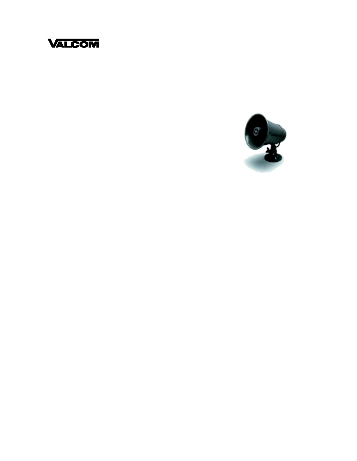
MOUNTING
Loosen the wing nut and remove the tapere d locking pin. Separate the horn from the bracket.
Mount the bracket using appropriate hardware
(not supplied). Position the horn back on the
bracket for optimum sound direction and install
locking pin and wing nut. (see Figure 1).
WIRE CONNECTIONS
A clear plastic cover protects the horn screw terminals and provides strain relief for the wires.
1. Remove the two screws from the plastic cover.
2. Connect the audio wires to the horn.
3. Connect the (+) side of the speaker wire to terminal 2. Connect the (-) common side of the
speaker wire to terminal 1 (see Figure 2).
1947175
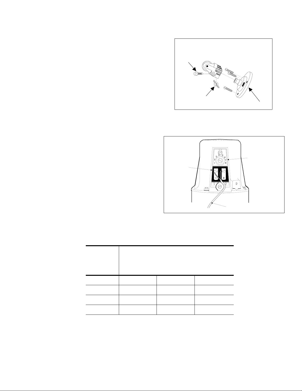
4. Do not replace the plastic cover until final
SPEAKER CABLE
VOLUME LEVE L
CONTROL
(USE ONLY SETTINGS
1 TO 4)
TERMINALS
power adjustments have been made.
FINAL POWER ADJUSTMENTS
Ensure that the speaker is set to its lowest setting
(this will prevent an excessively loud page when
first used). While a page is in process, adjust the
volume control with a screwdriver. Turn clockwise
to increase the volume (see Table 1).
TECHNICAL ASSISTANCE
When calling, have a VOM and a telephone test
set available and call from the job site. Call (540)
427-3900 and ask for PagePac Technical Support, or call (540) 427-6000 for Valcom 24-hour
Automated Support or visit our websites at
http://www.pagepac.com and www.valcom.com.
Should repairs be necessary, attach a tag to the
unit clearly stating company name, address,
phone number , contact person, and the nature of
the problem. Send the unit to:
PagePac
5614 Hollins Road
Roanoke, VA 24019-5056
®
Repair Dept.
Valcom, Inc.
ANDING
OT
ED)
TAPERED
LOCKING
PIN
MOUNTING ON FLAT SURFACE
WING NUT
MOUNTING BRACKET
FIGURE 1
Table 1: SWITCH SETTINGS
SWITCH
SETTINGS IMPEDANCE
1 720 0.016 89
2 180 0.063 95
3450.25101
4 11.5 1.0 107
OHMS
FIGURE 2
3.4 Vrms Input
POWER SPL
WATTS DECIBELS
2947175
 Loading...