

Page 1

PagePac
®
by
Universal Voice Coil and
70 Volt Door Speaker
ISSUE 2
V-5330120 / V-5330230
Installation Manual
947179
Page 2
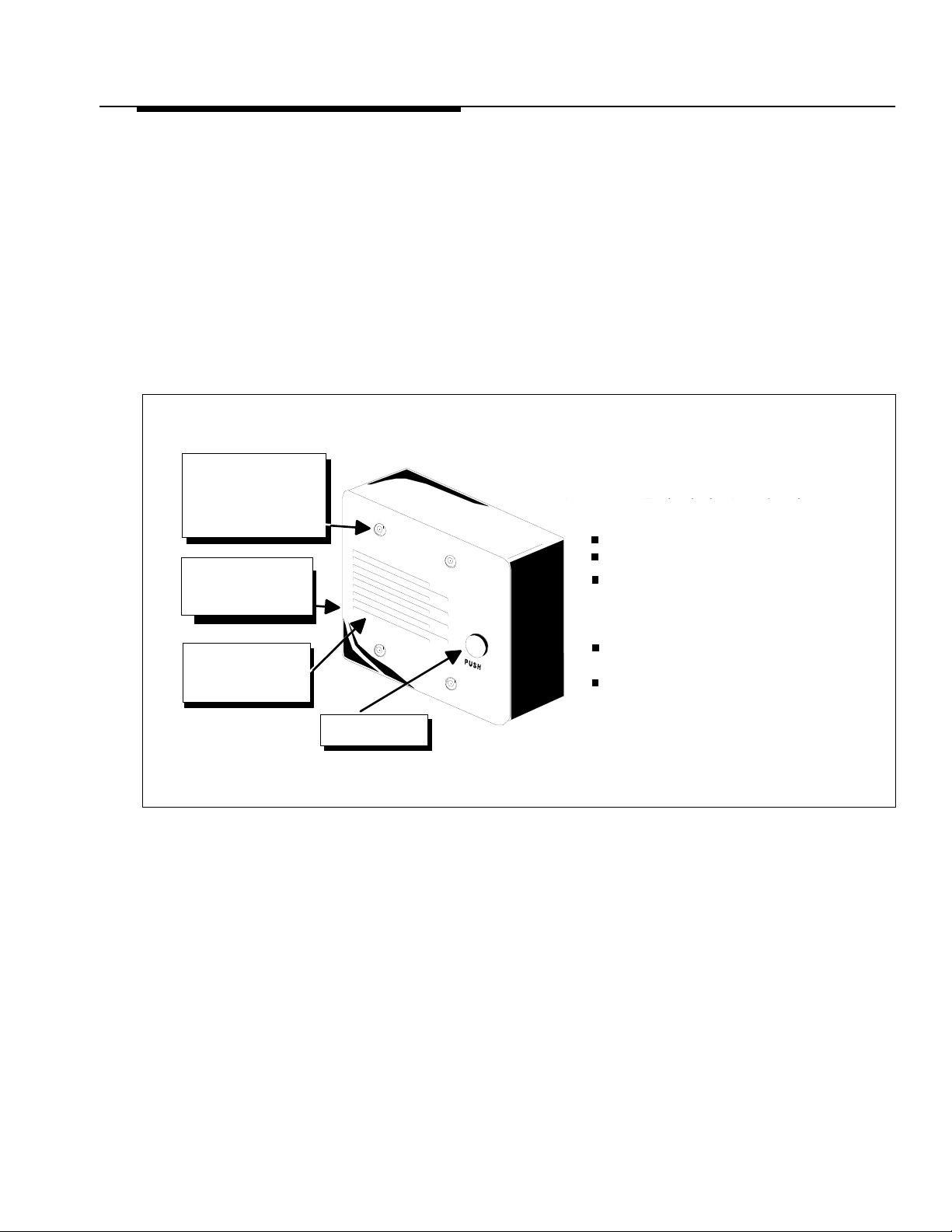
Your PagePac® Door Speaker
Note: The Door Phone
Controller an d
PagePac 6 systems
require that a V oice
Coil Door Speaker be
used. The PagePac 6
Plus system requires a
70 Volt Door Speaker
be used. (Additi onal
speaker can be added
to controller and
paging systems
mentioned).
DURABLE STAINLESS STEEL
FACEPLATE WITH FOUR
TAMPER RESISTANT
SCREWS (A SPECIAL ALLEN
WRENCH IS INCLUDED FOR
INSTALLATION).
STRONG WEATHER
RESISTANT ENCLOSURE
TO MEET BUILDING AND
SAFETY CODES.
INSIDE ENCLOSURE IS A
45 OHM (FOR VOICE-COIL
UNITS) OR 70 VOLT
SPEAKER
Your Door Speaker operates within a weather resistant enclosure ideal for indoor as well as
outdoor applications. When used in conjunction with the Door Phone Controller, PagePac 6,
or PagePac 6 Plus, persons within your office or building can speak directly with outside
visitors, through the telephone system. sBoth V oice Co il (V-5330120) and ffkfkjskgg kfgj kjgk
70 Volt (V-5330230) models are available.
Installation of double-gang electrical boxes, running of conduit, cutting through walls, etc.,
should be conducted by persons with appropriate technical skills; we highly recommended
installation be provided by a licensed electrician. Install per National Electrical Code and any
applicable local codes. This manual provides information for installing the Door Speaker to a
solid (surface mount) or nonsolid (flush mount) surface.
Your PagePac Door Speaker
Your Lucent Technologies Door Speaker
shipping box contains:
Door speaker unit
Faceplate (steel)
Weather resistant double-gang outdoor
electrical outlet box gasket, and surface
mounting hardware (screws and
brackets)
Tamper resistant (faceplate) mounting
screws (four) with driver tool
This instruction booklet
Note: For some wall
surfaces, such as
drywall, plastic wall
anchors may need to be
driven into the wall
surface to secure the
mounting screws.
PUSH-BUTTON TO
INITIATE SIGNALING
The Door Speaker can be mounted to virtually any type of surface or wall. Those surfaces that
are too hard or difficult to cut through require the unit to be SURFACE MOUNTED (device
installed so it is completely external to the wall surface). Wall surfaces such as wood or
drywall often are hollow and allow wiring to be run within the wall. Mounting the Door
Speaker unit to non-solid surfaces is often preferred because the unit can be FLUSH
MOUNTED so only the faceplate is exposed. Refer to the following pages for both surfacemount and flush-mount double-gang outlet box installations.
2 947179
Page 3

GANG BOX
MOUNTING
BRACKETS
WALL
SURFACE
PIPE OR CONDUIT
SURFACE MOUNTING
GANG BOX
WEATHER RESISTANT
DOUBLE-GANG OUTDOOR
ELECTRICAL BOX
(PROVIDED)
BRACE
CAUTION : SEAL TOP PLUG
WITH OUTDOOR SEALANT
SUCH AS SILICONE RUBBER
MOUNTING SCREWS
1
A
The gang box mounting
brackets (included) can be screwed
to the gang box back plate so they
protrude out the sides of the gang
box. Using the ap propriate screws
(depending o n the mate rial the wall is
made of), position the screws through
the bracket holes and using a
screwdriver secure the gang box to
the wall surface. Once the gang box
has been properly braced, install the
speaker unit and face plate as shown
in illust rati ons 4 and 5.
NOTICE:
—All conduit and
closure plug
connections
should be
adequately sealed
(i.e., pipe joint
compound) for wet
location
installations.
—Do not allow
conduit to
protrude into rear
opening of outlet
box to avoid
interference with
Door Speaker.
—The gang box
should be
grounded via the
conduit to a
suitable earth
ground to provide
protection against
lightning strikes.
B
Another method to attach the
gang box to the surface of a wall,
which is more secure and
provides.an esthetically pleasing
look, is to d rill mo unti ng h oles (4 )
directly into the back of the gang box.
Using the appropriate screws
(depending on the material the wall
surface is made of) position the
screws through the inside of the gang
box and using a screwdriver secure
the gang box to the wall. Once the
gang box has been properly braced,
install the speaker unit and face plate
as shown in illustrations 4 and 5.
FLUSH MOUNTING...
go to step 2.
3 947179
Page 4

STUD
S
BRACE GANG
BOX TO STUD
WALL SURFACE
FLUSH MOUNTING
2
Flush-mount surface installations
are often desirable because mounting hardware and wires are
hidden inside the wall. Steel double-gang indoor electrical
boxes mount directly to a stud. Once the gang box has been
properly braced to a stud, install the speaker unit and
faceplate as shown in illustrations 4 and 5.
TEEL DOUBLEGANG INDOOR
ELECTRICAL BOX
CONTROL UNIT
DOOR
SPEAKER
OUTPUT
DOOR BELL
BUTTO N
TERM INALS
2"
RUNNING WIRES
AUDIO PAIR
2 4 A W G S H IE L D E D T W IS T E D P A IR C A B L E
Note: Electrical box must be at least 2 inches deep to
accommodate door speaker.
LUCENT TECHNOLOGIES
DOOR SPEAKER
1
2
3
4
SPEAKER
DOOR BELL/
CHIME BUTTON
CONTROL PAIR
DO NOT CONNECT SHIELD
TO SPEAKER SIDE
NOTE: SEE STEP 4 FOR SPEAKER HOOKUP
3
Run the twisted pair wires
from the control unit, along with the pushbutton wires, to the installed double-gang
electrical box. Keep track of which colored
wire is connected to which device. R oute wires
through conduit (if necessary) and feed into
double-gang outlet box.
Check National Electrical Code and
applicable local codes and ordinances for
exact wiring requirements for your area.
Cut wires, leaving six (6) extra inches for connection to Door
Speaker’s terminal strip. Strip approximately 1/2 inch off one
end of each of the four wires.
The shield is not connected to any part of the speaker or gang
box. The shield is only connected at the Controller terminal
labeled “shield.”
Total length of wire from control unit to door speaker should
not exceed 1500 feet.
4 947179
Page 5

R
CONNECTING
h
SPEAKER WIRES
A L E R T S P K R
4 3 2 1
SHIELDED CABLE
DO NOT CONNECT
SHIELD TO SPEAKE
FINAL ASSEMBLY
GANG BOX
GASKET
SPEAKER UNIT
STEEL FACEPLATE
CONNECT W IRES TO TERMINAL BLOCK
4 5
The Door Speaker back panel has two sets of terminals:
one set is labeled SPKR and the other is labeled
ALERT. The two ALERT terminals are labeled 3 and 4,
and are connected to the doorbell input terminals of the
Controller. The other two terminals (1 and 2) are
labeled SPKR. The SPKR terminals connect to the
output of the Controller and must use shielded twisted
pair wire.
Loosen each of the terminal block screws and insert
exposed wire ends into appropriate terminal block
locations. Tighten terminal block screws. Ensure wire
connections are correct before continuing.
TAMPER PROOF SCREWS
DRAINAGE NOTCH ON
OF GASKET
BOTTOM
Use the allen wrench supplied to secure Door
Speaker and faceplate to double-gang outlet box wit
the four tamper proof mounting screws. (included).
Note: Be careful to place rubber sealing gasket in
speaker assembly so that drainage notch point s
down.
5 947179
Page 6

TECHNICAL ASSISTANCE
When calling, have a VOM and a telephone test set available and call from the job site. Call
(540) 427-3900 and ask for PagePac Technical Support, or call (540) 427-6000 for Valcom 24hour Automated Support or visit our websites at http://www.pagepac.com and www.valcom.com.
Should repairs be necessary, attach a tag to the unit clearly stating company name, address,
phone number, contact person, and the nature of the problem. Send the unit to:
Valcom, Inc.
PagePac
Roanoke, VA 24019-5056
®
Repair Dept.
5614 Hollins Road
6 947179
 Loading...