

Page 1

PagePac
®
by
Issue 1
CALL STACKER
V-5325150
INTRODUCTION
The Digital Voice Announcer Call St acker i s a micro proce ssor
based audio recording and announcement system. The Ca ll
St acker is used i n conjunction with a p aging sys tem to provide
buffered announcement play to the paging system.
SPECIFICATIONS (also see Table 3)
FEATURES
• Maximum Record Time - 3 Minutes • Battery Backup for up to 2 Hours
• Maximum of 30 Announcements • Rack Mountable - 19” (48.3cm)
• Announcement Verification • Pause Override Control
• 5 Analog Station Port Input Channels • Provides Audio Output and a Contact Closure
Power Requirements Dimensions/Weight
• 115 Vac, 60 Hz • 16.25”W x 1.75”H x 9.25”D
(41.28cm x 4.45cm x 23.50cm)
• 13.0 lbs (5.85 kg)
Environment • 19”W (48.3cm) with rack brackets
• Temperature: 0 to 40°C (32 to 104°F)
• Humidity: 5 to 95%
OPERATION
The Call Stacker features 5 Input Station (recording) channels, a single Page Output channel and
3 minutes of recording time.
Up to 5 announcements can be recorded simultaneously, virtually elimi nating frustrating delays
encountered when accessing the paging system. The recorded announcements are queued in order so
the first complete announcement recorded, plays first, followed by the second announcement, etc.
The Call Stacker allows users to verify their announcements before they play to the paging system. If a
user is not content with their recorded announcement, they can re-record it repeatedly until they are
satisfied.
The Call Stacker's Page Output channel interfaces to the paging system's control unit. Once an
announcement is recorded, the Call Stacker plays the announcement over the Page Output channel to
the paging system. While the recorded announcement is playing, the Page Output channel provides a
contact closure to the pagi ng system.
Once the complete recorded announcement plays to the pagi ng system, it is erased from the Call
Stacker, freeing up the recording time for new announcements.
The Call Stacker can be configured to record and play back paging zone selection signals. Between 2
and 4 DTMF digits can be ent ered prior to recording an announcement which, upon output, precede the
recorded announcement and select the paging system's paging zone.
1 947186
Page 2
NOTE: Associated equipment would need to be powered by an uninterrupted power supply.
The Call Stacker is equipped with battery backup which allows it to operate for up to two hours, from a
fully charged battery, if a power failure occurs.
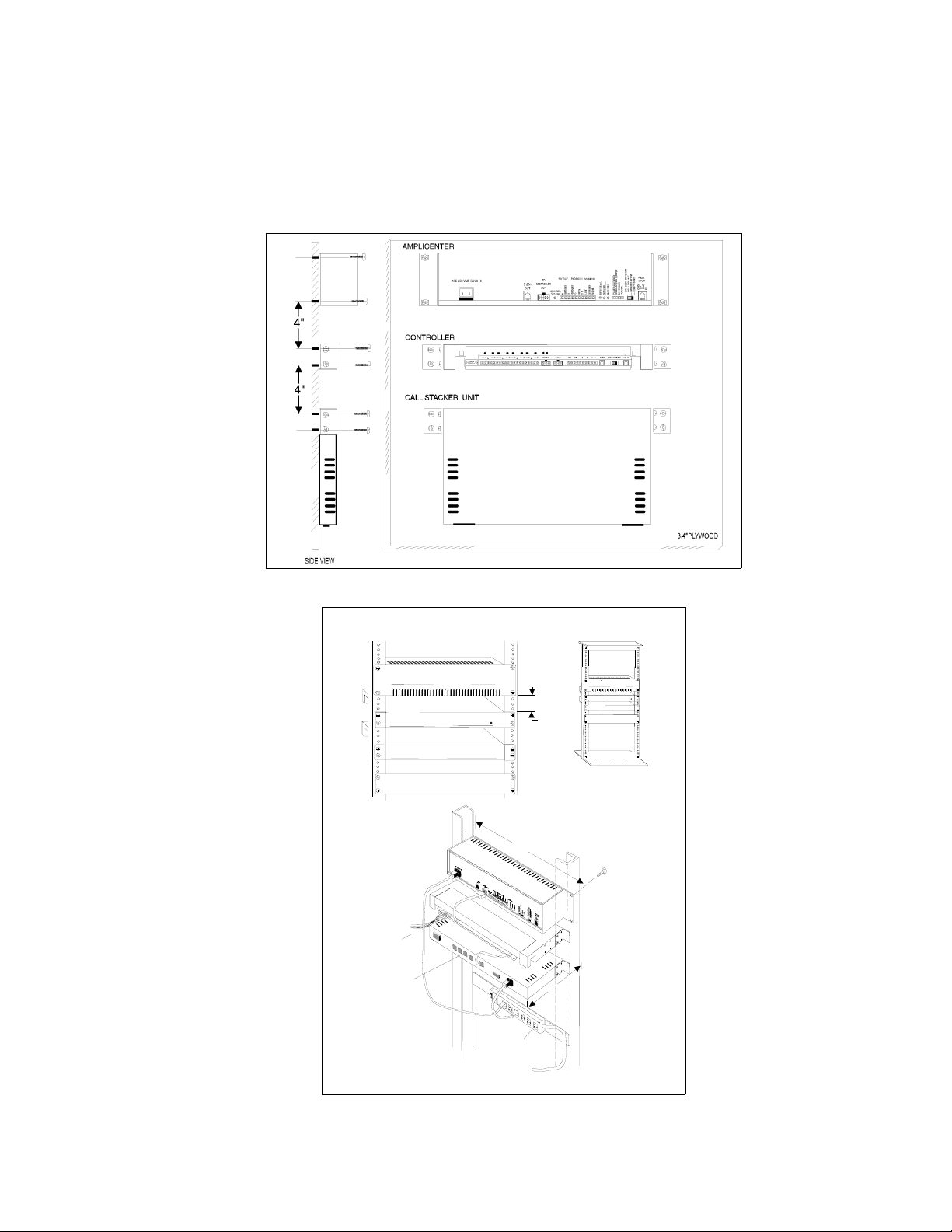
INSTALLATION
1. Attach the reversible 19/23" brackets to the Call Stacker using t he 6-32 x 3/8" screws provided, then
secure the Call Stacker to a back board or into an equipment rack.
Figure 1. Wall Mounted Unit
FRONT DETAIL
â
PagePac Plus
AmpliCenter D300
â
POWER
4.0"
TYPICAL
19''
10''
REAR DETAIL
ZONE
WIRING
TEL LINE
INPUT
CHANNELS
Call Stacker
PagePac Plus
Controller
Call Stacker
COMBINATION
PAN HEAD
PILOT POINT
# 12 - 24 (TYP IC A L)
PagePac Plus
AmpliCenter D300
PagePac Plus
Controller
â
POWER
â
POWER STRIP
Figure 2. Rack Mounted Unit
2 947186
Page 3

2. Set the option switch on the Cal l Stacker (see Figure 5) for the de sired s ystem configur ation (r efer t o
Table 1).
Table 1. Option Swit c h Sett in g
SET
SWITCH
# 1 TO
Number of DTMF Digits in Zone Code
0 ONON—————
2 OFFON—————
3 ONOFF—————
4 OFFOFF—————
Voice Prompts
None — — ON ON — — —
English only — — OFF ON — — —
Spanish only——ONOFF———
English/Spanish — — OFF OFF — — —
Length of Recording C ut Of f ( whe n us e r han gs up dur in g r e co rding)
None ————ONON—
0.25 sec ————OFFON—
0.50 sec ————ONOFF—
0.75 sec ————OFFOFF—
Confirmation or Pre-Announcement Tone
2 Second Delay——————
SET
SWITCH
# 2 TO
SET
SWITCH
# 3 TO
SET
SWITCH
# 4 TO
SET
SWITCH
# 5 TO
SET
SWITCH
# 6 TO
SET
SWITCH
# 7 TO
SEE NOTE
NOTE: When switch #7 is “OFF”, there will be no delay in time from when the paging system zone is
accessed until the time when the message is sent. When switch #7 is “ON”, ther e will be a 2 second
delay from when the paging system/zone is accessed until the time when the message is sent. The
delay is installed in order for a Confirmation/Pre-announcement tone (if available or optioned) to be
played over the system before the message is sent.
3. Connect the Call S tacker to the paging system (see Figure 4):
• Connect the Call Stacker's Pause Override Control input to the attendant override (attendant
access control leads) or incoming alarm signal from the paging system.
• Connect one or more of t he Call Stacker's Input S ta tion channel s to PBX/KTS anal og st ation inputs
on the telephone system through FCC/DOC approved modular jacks. Connect the Cal l Stacker's
Page Output channel to the paging system as shown in Figures 4 and 5 through an FCC/DOC
approved modular jack. The contr ol contact signal is use d to secure and rel ease the pagi ng system
controller.
3 947186
Page 4

Figure 3. Page Output Channel Connection of Call Stacker
(
)
Figure 4. Connection to Paging System
NOTE: The zone contact closure output must be programmed as a Zone Output type “AA READY” if the
Attendant Access input is used.
AM PLICENTER
115-24O V A C , 60/5O H z
PAGE IN
S E T M O D E S W IT C H
TO D RY LO O P 600 O H M
POWER
PAUSE OVERRIDE CONTROL
CALL STACKER
INPUT STATIONS
STA1 STA2 STA3
STA4 STA5
PAGE
OUTPUT
PBX and KTS AN ALOG STATION
INTERFACES
TIP/RING
OPTION
SWITCH
BATTERY
OFF ON
120 VAC 0.1 AMP
Figure 5. Connection to AmpliCenter (Optional)
NOTE: The connection to the AmpliCenter depicted in Figure 5 is used instead of a connection directly
to the Controller.
4 947186
Page 5

NOTE: PBX and KTS stations must have the ability to send a forward disconnect to the Call Stacker's
Station inputs.
4. Connect the detachable power supply co rd to a 110/120 VAC outlet and the Call Stacker and veri fy
the Power LED illuminates.
5. Turn the battery switch ON.
CONTROLS AND INDICATORS
Figure 6. Rear Panel Detail
Table 2. Rear Panel Description
ITEM DESCRIPTION
Power On LED Illuminates when power is supplied to the Call Stacker.
Enables/disables the Page Output channel. When a contact closure
(a short) between the two terminals is detected, the Call Stacker
Pause Override Control
Input
Input Station
(record) Channels
Page Output Cha nnel
Option Switch See table 1.
Battery Switch
Power Input 110/120 VAC, 60Hz, power input
NOTE: The Input Station channels continue to operate when a contact closure is detected. Recorded
announcements are held in a queue and play out se que ntially (first in, first out) when the c ontact closure is
removed.
terminates the outgoing announcemen t (if any), requeues it and
disables the Page Output channel. When the contact closure is
removed, the Page Output chan nel is re-enabled and the term inated
announcement plays to the paging system in its entirety (see note
below).
PBX and KTS analog station interfaces (tip/ring pairs) to the
Public Telephone Network, a PABX or a Key System.
Audio and control contact signals to the paging system as shown in
figure 6. Between outgoing announcements the control contact
opens for a minimum of 250 msec. t o rel ease the paging system
controller.
Enables/disables battery backu p. Turn the switch ON to enable the
battery backup .
5 947186
Page 6

RECORDING ANNOUNCEMENTS
VOICE PROMPTS ENABLED
1. Dial up the input station connected to the Call Stacker. The Call Stacker answers the station and
responds “Enter zone code (Marque el codigo de la zona)”. Proceed to step 2.
2. Enter a DTMF tone sequence using the telephone keypad to select a paging zone.
• Once the required number of DTMF digits (see Table 1) are entered, the Call Stacker responds
“Start recording, press the pound key to end or hang up (Empieze a grabar el mensage, para ter minar la grabación cuelge o marque la tecla de numero)” followed by a high to ne.
Proceed to step 3.
NOTE: If the number of digits in the paging zone is set to 0 (see Table 1), the Call Stacker answers the
station and responds “Sta rt re cording, p ress t he poun d key t o end or hang up ( Empiez e a grabar e l mensage, para terminar la grabación cuelge o marque la tecla de numero)” followed by a high tone. Skip
step 2 and proceed to step 3.
Important: If all the recording time is used up, the Call Stacker answers the station and responds with
“No recording time available (No hay tiempo de grabación disponible)” or “Message not recorded (No
hay mensajes grabados)” then disconnects. If this occurs wait a few seconds before re-attempting to
record the announcement.
3. Record the announcement. To end recording, either:
• Hang up to enter the recorded announcement into the queue, or
• Press the “#” key to hear the recorded announcement. The Call Stacker responds “Hang up if finished, press zero to re-record or stay on the line to rev iew your message (Cuando termine de grabar cuelge, marque la tecla cero para regrabar, o siga en la linea para escuchar el mensage
grabado)”, plays back the recorded announcement and then responds “Hang up if finished, press
zero to re-record (Cuando termine de grabar cuelge, marque la t ecla cero para regrabar)”. Press
the “0” key to re-record the annou ncement a nd return to step 2 or hang up t o accept t he announce ment and enter it into the queue.
NOTE: Press the “#” key w hile the voice prompts are playing to interrupt (and skip) them
VOICE PROMPTS DISABLED (Switch 3 & 4 ON)
1. Dial up the input station connected to the Call Stacker and wait for the Call Stacker to answer the
station and respond with a high tone. Proceed to step 2.
NOTE: If the number of di gits in the paging zone code i s set to 0 (see Table 1), skip step 2 and proceed
to step 3.
2. Enter a DTMF tone sequence using the telephone keypad to select a paging zone. Once the
required number of DTMF digits (see Table 1) are entered, the Call Stacker responds with a high
tone. Proceed to step 3.
3. Record the announcement. To end recording, either:
• Hang up to enter the recorded announcement into the queue, or
6 947186
Page 7

• Press the “#” key to hear the recorded announcement. The Call Stacker responds with a high tone,
plays back the recorded announcement and then responds with a second high tone. Press the “0”
key to re-record the announcement and return to step 2 or hang up to acce pt the announcement
and enter it into the queue.
Important: If all the rec ording ti me is used up, the Call Stacker r esponds wit h two consecut ive l ow tones
then disconnects. If this occurs your announcement has not been recorded. Wait a few seconds before
re-attempting to record the announcement.
ANNOUNCEMENT PLAYBACK
Once a recorded announcement is entered into the queue, the Call Stacker immediately closes the control contact on the Page Output channel to access the paging system cont roller.
The Call Stacker then plays out the recorded DTMF sequence to select t he paging zone foll owed by the
recorded announcement.
At the end of the announcement the Call Stacker erases the announcement and opens the control contact on the Page Output channel to release the paging system controller.
NOTE: If more than one announcement is in the queue, the control contact remains open f or a minimum
of 250 msec.
Important: If at any time a contact closure is detected on the Pause Override Control Input, the Call
Stacker immediately terminates the outgoing announcement and requeues it for playback in its entirety
once the contact closure is removed.
SPECIFICATIONS
Table 3. Call Stacker Unit Specifications
SPECIFICATION DESCRIPTION
Recording Time 3 minute base unit.
Input Lines 5 analog station ports.
Output Lines 1 page output channel.
Number of stacked
Announcements
Altitude: Sea level to 10,000 ft. operat io nal (1048 to 648 millibars) 40,000 ft. m ax. shi p m en t.
Environmental Locate in an area f ree of excess moistu re , corrosive gases, dus t, and chemicals.
Battery Backup All ows up to two hours of operation duri ng a power failure. Total charge time 48 hours.
Frequency Response 200 Hz to 3.4 kHz ( ±3 dB).
Output Level –9 dBm.
Control Contact Rating
30 individual announcem e nts.
0.3 A / 60 VDC
1.0 A / 24 VDC
0.5 A / 120 VAC
7 947186
Page 8

TECHNICAL ASSISTANCE
When calling, have a VOM and a telephone test set available and call from the job site.
Call (540) 427-3900 and ask for PagePac Technical Support, or call (540) 427-6000 for Valcom 24-hour
Automated Support or visit our websites at http://www.p agepac.com and www.valcom.com.
Should repairs be necessary, attach a tag to the unit clearly stating company name, address, phone
number , contact person, and the nature of the problem. Send the unit to:
Valcom, Inc.
PagePac
5614 Hollins Road
Roanoke, VA 24019-5056
FCC
This equipment complies with Part 68 of the FCC rules. On the rear of the digital voice announcer is a
label that contains, among other information, the FCC registration number and ringer equivalence number (REN) for this equipment. If requested, this information must be provided to the telephone company.
The USOC for this equipment is RJ11C. The facility i nterface code is 02LS2 and the service order code
is 9.0F. This equipment is hearing aid compatible.
®
Repair Dept.
The ringer equivalence number (REN) is used to determine the quantity of devices which may be connected to the telephone line. Excessive REN's on the t elephone line may res ult in the devices not r inging
in response to an incoming call. In most, but not all areas, the sum of the REN's should not exceed five
(5.0). To be certain of the number of devices that may be connected to the line , as determined by the
total REN's contact the telephone company to determine the maxi mum REN for the calling area.
If the digital voice announcer causes harm to the telephone networ k, the telephone company will notify
you in advance that temporary discontinuance of service may be required. But if advance notice isn't
practical, the telephone company will notify the customer as soon as possible. Also, you will be advised
of your right to file a complaint with the FCC if you bel ieve it is necessary.
The telephone company may make changes in it's facilities, equipment, operations, or procedur es that
could affect the operati on of the equip ment. If thi s happens, the telephone company wil l provid e advance
notice in order for you to make the necessary modifications in order to maintain uninterrupted service.
This equipment cannot be used on public coin service provided by the telephone company. Conn ection
to Party Line Service is subject to state tariffs. Contact the state public utility commission, public service
commission or corporation commission for information.
FCC Registration Number: F4PCAN-20988-AN-N
Ringer Equivalence Number: 0.7B(ac); 2.6(dc)
8 947186
Page 9

DOC
The Canadian Department of Communications label identif ies certified equipment. This cert ification
means that the equipment meets certain telec ommunicat ions networ k protect ive, oper ati onal and saf ety
requirements. The Department does not guar antee that the equi pment wil l operat e to t he user' s satis faction.
Before installing this equipment, users should ensure that it is permissible to be connected to the facilities of the local telecommunications company. The equipment must also be installe d using an approved
method of connection. In some cases, the company's inside wiring associated with a single line individual service may be extended by means of a certified jack-plug-cord ensemble (telephone extension
cord). The customer should be aware that compliance with the above conditions may not prevent degradation of service in some situations. Existing telecommunications company requirements do not permit
their equipment to be connected to customer-pr o vided jacks, except where specified by individual telecommunications company tariffs.
Repairs to certified equipment should be made by an authorized Canadian maintenance facility designated by the supplier. Any repairs or alterat ions made by the user to this equipment, or equipment malfunctions, may give the telecommunicati ons company cause to request the user to disconnect the
equipment.
Users should ensure for their own protection that the electrical ground connecti ons of the power utility,
telephone lines and internal metallic water pipe system, if present, are connected together. This precaution may be particularly important in rural areas.
Caution: Users should not att empt to make such connec ti ons themsel ves, but sho uld cont act the appropriate electrical inspec tion authority, or electrician, as appropriate.
DOC Certification Number: 5576106A
Load Number: 26
The Load Number (LN) assigned to each terminal device denotes the percentage of the total load to be
connected to a telephone loop which is used by the device, to prevent overl oading. The terminat ion on a
loop may consist of any combination of devi ces subj ect only to t he requi rement th at t he total of the Load
Numbers of all the devices does not exceed 100.
NOTE: This digital apparatus does not exceed the Class A limits for radio noise emission from digital
apparatus set out in the radio interference regulations of the Canadian Department of Communications.
9 947186
 Loading...