

Page 1
PagePac
®
by
Issue 1
MULTIPLE DIGITAL MESSAGING UNIT
V-5325100
INTRODUCTION
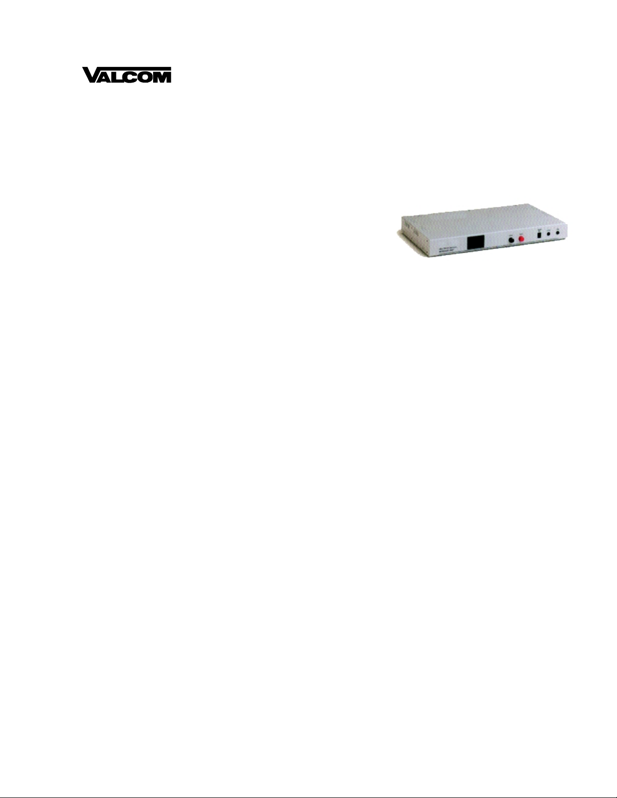
The Multiple Digital Messa ging Unit (MDMU) is a microp rocessor
based digital voice announcement system. It outputs
prerecorded messages through a public addre ss system. Up to
99 messages can be placed in the units digit al memory for
queued replay. Up to eight messages can be programmed to
play in sequence with timed delays.
The MDMU can store up to 3 minutes and 1 5 seco nds of messag es. Voice and audio messages can be
stored into memory through dial-up telephone, microphone interface, or tape input.
(The MDMU is programmed by dial-up telephone DTMF tones.)
This guide gives installation, recording, and programming steps. Sin ce messages are digitally stored,
and there are no moving parts, the MDMU should give years of uni nterrupted service.
Power Requirements
• 115 Vac, 60 Hz
Dimensions/Weight
• 16.3”W x 1.8”H x 9.3”D
(41.3cm x 4.5cm x 23.5cm)
• 13.0 lbs (5.9 kg)
Environment
• Temperature: 0 to 40°C (32 to 104°F)
• Humidity: 5 to 95%
1 947193
Page 2
INSTALLATION
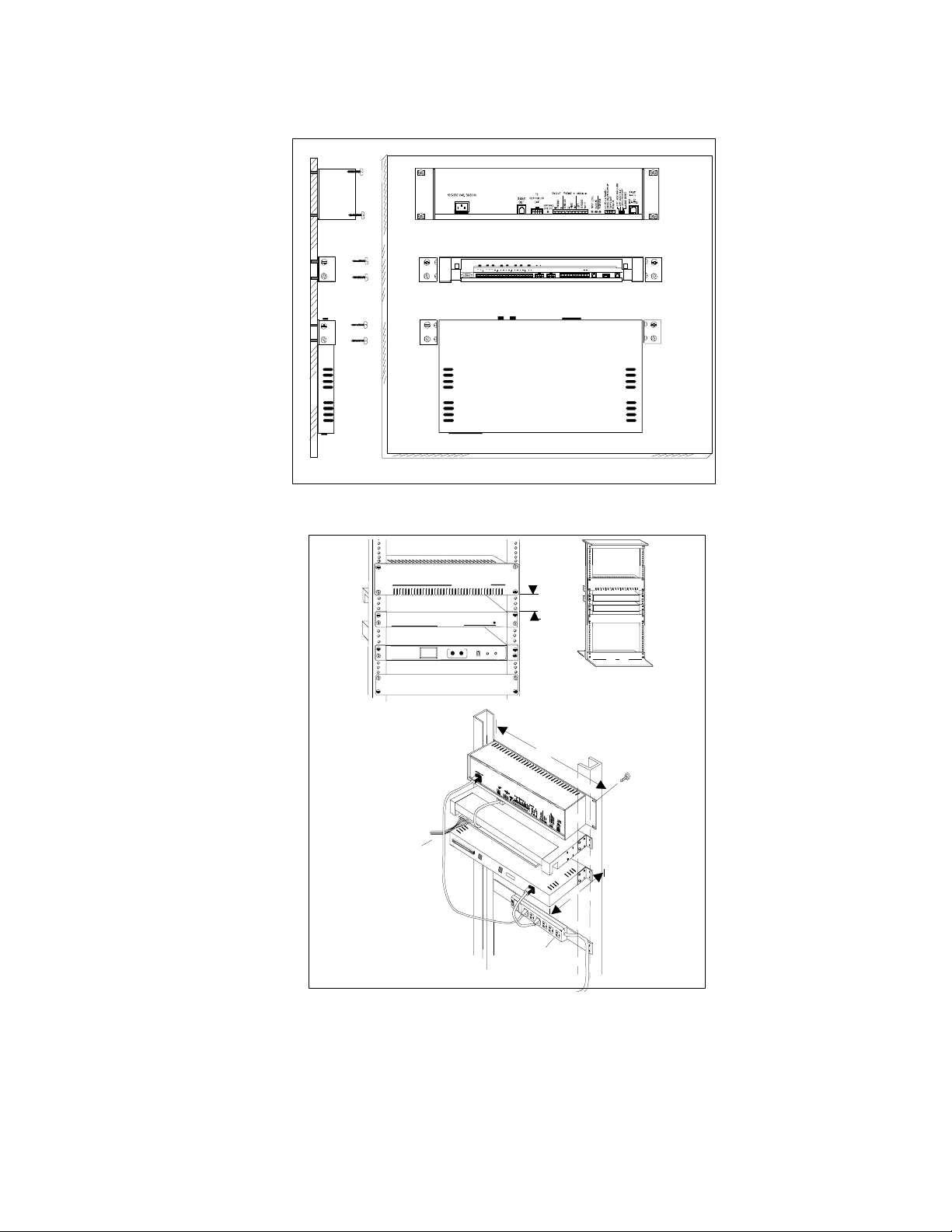
1. Mount the MDMU to either a wall, cabinet or a rack (near the paging equipment if possible).
AMPLICENTER
CONTROLLER
MULTIPLE DIGITAL MESSAGING UNIT
3/4" PLYWOOD
SIDE VIEW
Figure 1. Wall Mounted MDMU
MULTIPLE DIGITAL
MESSAGING UNIT
REAR DETAIL
ZONE
WIRING
FRONT DETAIL
PagePac Pl us
AmpliCente r D300
PagePac Plus
Controller
FUNC
POWER
4.0"
TAPE MIC
POWER STRIP
TYPICAL
COMBINATION
PAN HEAD
10''
PILOT POINT
# 12 - 24 (TYPICAL)
19''
HAND
RUN
SET
Figure 2. Rack Mounted MDMU
2. Connect the MDMU to the telephone system.
2 947193
Page 3
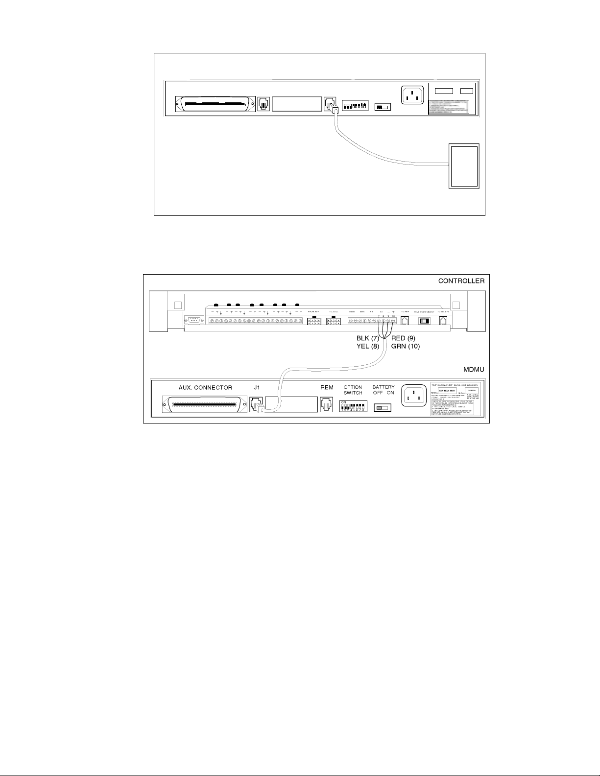
AUX. CONNECTOR J1
REM
OPTION
SWITCH
ON
1 2 3 4 5 6 7 8
BATTERY
OFF ON
TIP AND RING FROM
ANALOG STATION
TELEPHONE EQUIPMENT - DIGITAL VOICE ANNOUNCER
MODEL
FCC REGISTR ATION No. F4 P 4LB - 1 6578-AN -N
CONNECT T O USOC RJ11C OR RJ21X
DOC LOAD No. 26
SMU-4RAB-MDMU
543210
SERIAL
R.E.N.= 0.7B(ac);
2.6(dc); 120VAC,
60Hz, 0. 1A, 12W
HOST
TELEPHONE
SYSTEM
Figure 3. MDMU Connection to telephone system
3. Plug the modular cord into connector J1 on MDMU and connect the wires on the other end to the
Controller Attendant Access terminals.
Figure 4. MDMU Connection to Controller Attendant Access
4. Connect the RJ-21 cable/connector to the MDMU Aux. Interf ace and to terminal block.
NOTE: For specific pin-out information for this connector refer to Figure 5.
Messages 1 through 6 correspond to message start s 1 through 6.
3 947193
Page 4
AUX. CONNECTOR J1
RJ-21 CAB LE AND
CONNECTOR
25 PAIR
CABLE
REM
OPTION
SWITCH
ON
1 2 3 4 5 6 7 8
BATTERY
OFF ON
26
1
27
2
28
3
29
4
30
5
31
6
32
7
33
8
34
9
35
10
36
11
37
12
38
13
39
14
40
15
41
16
42
17
43
18
44
19
45
20
46
21
47
22
48
23
49
24
50
25
TELEPHONE EQUIPMENT - DIGITAL VOICE ANNOUNCER
SERIA LMODEL
FCC REGISTRATION No. F4P4LB-16578-AN-N
CONNECT TO USOC RJ11C OR R J21X
DOC LOAD No. 26
W/BL
BL/W
W/O
O/W
W/GR
GR/W
W/BR
BR/W
W/S
S/W
R/BL
BL/R
R/O
O/R
R/G
G/R
R/BR
BR/R
R/S
S/R
BK/BL
BL/BK
BK/O
O/BK
BK/G
G/BK
BK/BR
BR/BK
BK/S
S/BK
Y/BL
BL/Y
Y/O
O/Y
Y/G
G/Y
Y/BR
BR/Y
Y/S
S/Y
V/BL
BL/V
V/O
O/V
V/G
G/V
V/BR
BR/V
V/S
S/V
543210SMU-4RAB-MDMU
R.E.N.= 0.7B(ac);
TYPICAL CONNECTION
2.6(dc); 120VAC,
60Hz, 0.1A, 12W
TO 66 PUNCHDOWN BLOCK
J1 TIP
J1 RING
START 1 (-)
CP 1 (C)
START 1 (+)
CP 1 (NC)
CP 1 (NO)
START 2 (-)
START 2 (+)
START 3 (-)
START 3 (+)
START 4 (-)
START 4 (+)
ALARM (NC)
START 5 (-)
START 5 (+)
ALARM (NO)
START 6 (-)
START 6 (+)
ALARM (C)
TIP RE MOT E
RING REMOTE
CONTACT CLOSURE
TO ACTIVATE
MESSAGE #1
CONTACT CLOSURE
TO ACTIVATE
MESSAGE #2
CONT ACT CLOSUR E
TO ACT IVAT E
MESSAGE #3
CONT ACT CLOSUR E
TO ACTIVATE
MESSAGE #4
CONTACT CLOSURE
TO ACTIVATE
MESSAGE #5
CONT ACT CLOSUR E
TO ACTIVATE
MESSAGE #6
Figure 5. Connection of RJ-21 cable to MDMU and 66 Punchdown Block
5. Set the MDMU options on the DIP switch. Refer to Table 1.
NOTE: Switches 1, 2 and 3 set the number of messages in a single queue sequence. The timing
between those messages is set by switches 4, 5 and 6. Switch 7 sets the tot al possible number of
messages for the unit. Switch 8 is always in the ON position.
Figure 6. Set MDMU Options o n DIP Switch
4 947193
Page 5
Table 1. DIP Switch Setting Definitions
MAX. No. of
Messages in
Sequence
1ONONON-------2 OFF ON ON -- -- -- -3 ON OFF ON -- -- -- -4OFFOFFON-- -----5 ON ON OFF -- -- -- -6OFFONOFF-- -----7ONOFFOFF-------8 OFF OFF OFF -- -- -- --
DEFAULT DELAY BETWEEN MESSAGES:
0:05 -- -- -- ON ON ON -0:10 -- -- -- OFF ON ON -0:30 -- -- -- ON OFF ON -1:00 -- -- -- OFF OFF ON -5:00 -- -- -- ON ON OFF --
SET
SWITCH
#1 TO
SET
SWITCH
#2 TO
SET
SWITCH
#3 TO
SET
SWITCH
#4 TO
SET
SWITCH
#5 TO
SET
SWITCH
#6 TO
SET
SWITCH
#7 TO
15:00 -- -- -- OFF ON OFF -30:00 -- -- -- OFF OFF OFF --
NUMBER OF MESSAGES AVAILABLE:
1 TO 9
01 TO 99
-- -- -- -- -- -- ON
POWER UP SYSTEM
1. Plug the power cord into the AC input connector on the MDMU, then into the wall outlet.
The MDMU will display three messages in sequence:
MDMU 2.00
Software version of unit.
3:16
Total time available in memory for recording.
IDLE
Indicates the status MDMU:
Idle = no activity
PLY = a message is being played out through connector J1
Delay = the time delay between successive messages is active
OFF
5 947193
Page 6

2. Push the Battery slide switch to the ON position.
The MDMU is now ready to record and play messages.
NOTE: The internal battery maintains the recorded messages two hours in the event of a power failure
or brownout. Allow 48 hours to fully charge. If power is to be removed from the MDMU for an extended
period of time, turn the battery switch to the OFF position to avoid permanent damage to the battery.
NOTE: The suggested re liable lif etime of the rechar geable batter y used in the equi pment is 36 months .
To ensure the system has reliable battery backup, it is recommended the battery be replaced every 30
months.
Figure 7. Battery Switch
FRONT PANEL OPERATION
The MDMU can record messages input from the front panel through the hand set, tape and mic
connectors. The unit can also record and store messages input remotely through telephone access to
the REM port using a DTMF (touch tone) telephone.
CONTROLS AND INDICATORS
FRONT VIEW
HAND
SET
HANDSET
INPUT
TAPE
INPUT
MICTAPE
MIC
INPUT
MULTIPLE DIGITAL
MESSAGING UNIT
IDLE
FUNCTION
DISPLAY
FUNCTION
SELECTION
BUTTON
RUNFUNC
RUN
FUNCTION
BUTTON
REAR VIEW
POWER
INPUT
TELEPHONE EQUIPMENT - DI GITAL VOICE ANNOUNCER
SMU-4RAB-MDMU
MODEL
SERIAL
FCC REGISTRATION No. F4P4LB-1657 8-AN-N
CONNECT TO USOC RJ11C OR RJ21X
DOC LOAD No. 26
THIS DEVICE COMPLIES WITH PART 15 AND PART 68 OF THE FCC RULES. OPERATION IS SUBJECT TO THE FOLLOWING TWO CONDITIONS:
R.E.N.= 0.7B(ac) ;
2.6(dc ); 120VAC,
60Hz, 0.1A, 12W
543210
AUX. CONN EC TOR J1
50 PIN RJ-21
CONNECTOR
MESSAGE
OUTPUT
TELEPHONE
ACCESS
REM
OPTION
SWITCH
ON
1 2 3 4 5 6 7 8
OPTION
SWITCH
BATTERY
OFF ON
BATTERY
SWITCH
Figure 8. Controls and Indicators
RECORDING MESSAGES
The highest priority message should be recorded on the lowest message number (1) to ensure fastest
replay (i.e., fire in building...).
1. Plug the telephone handset, microphone or t ape player into the appropriate connector on the front
panel.
2. Press the (black) FUNC button until the RECORD message is displayed.
RECORD
6 947193
Page 7

3. Press the (red) RUN button to display the message #1.
MSG-1
4. To record on another message number, press the FUNC key until the desired message number
appears.
5. Press the RUN button and begin speaking into the handset, microphone or press the play on the
tape player.
SURE ?
mm:ss
6. When recording is complete, press the FUNC key.
The display shows the amount of time
used for the message:
TIME
0.30
DONE
IDLE
7. Repeat steps 2 through 6 to record other messages.
LISTENING TO RECORDED MESSAGES
1. Press the FUNC button until the display indicates monitor.
MONITOR
NOTE: Use the front panel handset to listen to messages.
2. Press the RUN button to sel ect the message number.
MSG-01
3. Press the FUNC button until desired message number appears.
4. Press RUN button to listen to the message.
MSG-11
7 947193
Page 8

NOTE: As the message plays into the handset, the display counts down the message time.
mm:ss
Length of message.
DONE
Done playing message.
PLAYING MESSAGES
Once messages have been recorded, they may be played over the paging system as described below.
Messages can also be queued by a contact cl osure of one of the pairs of the RJ-21 cable (see Figure 5).
1. Press the FUNC button until PLAY is displayed.
PLAY
2. Press the RUN button.
MSG-01
The first message displayed.
3. Press the FUNC button to select a message other than MSG-01 to play in.
MSG-09
4. Press RUN to play the message.
PLY-S09
Ply = Play, message #9 out of sequence.
DEL-S09
Configured delay between the messages (see Table 1).
NOTE: If a contact closure comes in on the RJ-21 ca ble, the mess age sequence will stop. The contact
closure message will play unt il the closur e is r emoved. The s equence message will resume wher e i t le ft
off.
PLAYING MESSAGES IN SEQUENCE
A group or sequence of messages can be played to the output channel. The maximum number of
messages in a sequence can be up to 8 (determined by the DIP switch settings on the back panel). To
add messages to the sequence simply repeat the PLAY command, selecting the message to be added
each time.
8 947193
Page 9

1. Press the FUNC button until PLAY is displayed.
PLAY
2. Press the RUN button.
MSG-01
The first message displayed.
3. Press the FUNC button to select a message other than MSG-01 to play in.
MSG-09
4. Press RUN to play (and group) the message.
PLY-S09
Ply = Play, S = sequence message #9.
5. Repeat steps 1 through 4 to add up to 8 messages if you are configured for 8 (see pages 7-8).
NOTE: If a contact closure comes in on the RJ-21 ca ble, the mess age sequence will stop. The contact
closure message will play unt il the closur e is r emoved. The s equence message will resume wher e i t le ft
off.
ADDING A TIME DELAY BETWEEN MESSAGE PLAYS
A time delay can be inserted before successive message plays. The amount of time depends on the
maximum time delay set on the option DIP switch.
1. Press the FUNC button until DELAY appears.
DELAY
2. Press the RUN button to di splay the message numbers.
MSG-01
3. Press the FUNC button to select the message number to add the delay.
MSG-04
4. Press the RUN button to display the delay times.
DLY-0:05
9 947193
Page 10

5. Press the FUNC button to scroll the available delay times.
DELAY
6. Press the RUN button to accept the selected delay time.
DELAY
7. Repeat steps 1 through 6 to add delays to other message numbers.
CLEARING A MESSAGE SEQUENCE
The message sequence can be cleared leaving the individual messages to be played separately.
1. Press the FUNC button until PLAY is displayed.
PLAY
2. Press the RUN button.
MSG-01
3. Press the FUNC button until the following message is displayed.
MSG-00
This is the message abort number.
4. Press the RUN button to clear the message sequence.
CLEARED
DONE
IDLE
CHECKING MESSAGE TIMES
The TIME function displays the time used for each message recorded. It also displays the remaining
time available in system memory to record other messages.
1. Press the FUNC button until TIME is displayed.
TIME
10 947193
Page 11

2. Press the RUN button to view message numbers and recording time.
MSG-01
Message number.
mm:ss
Time used to record message.
3. Once all messages and times are displayed, the display indicates:
LEFT
Amount of time left on the system to record other messages.
2:09
Available MDMU memory time in minutes and seconds.
DONE
RESET DELAY TIMES TO DEFAULT
The INIT (initialize) function resets the operating parameters and delay time to the default set ting of five
seconds without effecti ng the recorded messages.
1. Press the FUNC button until INIT is displayed.
INIT
2. Press the RUN button.
SURE ?
Verification of command.
3. Press the RUN button to init ialize.
WAIT
DONE
AUDIO AND MEMORY TESTS
Two diagnostic tests are built into the MDMU internal software. The audio test plays a 1000 Hz tone to
the installed J1 output line. The memory test clear s all recorded messages and internally writes and
reads a number of test patterns to verify proper operation.
11 947193
Page 12

AUDIO TEST
1. Press the FUNC button until TEST is displayed.
TEST
2. Press the RUN button to di splay the test options.
AUD TEST
3. Press the RUN button again to begin the test.
4. Press the FUNC button to end the continuous audio test.
WAIT
IDLE
MEMORY TEST
1. Press the FUNC button until TEST is displayed.
TEST
2. Press the RUN button to di splay the test options.
AUD TEST
3. Press the FUNC button to select the memory test.
MEM TEST
4. Press the RUN button to initialize the test.
SURE ?
Verification of memory test command.
5. Press the RUN button again to begin the test.
ADD TEST
0
This number indicates the number of times
the memory test has executed.
12 947193
Page 13

CAUTION: The memory test will erase all recorded and stored messages.
To cancel the memory test command, press the FUNC button.
6. Press the FUNC button to end the test.
DONE
TELEPHONE ACCESS OPERATION
The MDMU may be accessed remotely using a DTMF (Touch Tone) telephone. Telephone access can be
made directly through a telephone switching system with one of its analog stations connected to the
MDMU REM report.
RECORDING MESSAGES
1. Dial the telephone extension of the MDMU.
2. Press
3. When you hear the beep, begin recording the message.
4. Optionally, to send this message to a particular paging zone, dial the zone number now, then continue recording this message.
5. Press the
6. Press the
∗ 7 (R for record) and the message number. (For example, ∗ 76 - record message number 6)
# key to end recording and save message.
# key again to disconnect from the MDMU.
LISTENING TO RECORDED MESSAGES
1. Dial the telephone extension of the MDMU.
2. Press
(For example,
3. Press the
4. Press the
∗ 6 (M for monitor) and the message number.
∗ 609 - monitor message number 6)
# key to end monitoring message.
# key again to disconnect from the MDMU.
APPLICATION NOTES
While recording messages through the telephone access method, dial ing the paging controller zone
(before speaking) enables the pl ayback of this message to be routed to a Controller Zone or Zone Group
when replayed. You must, however, program the Contr oller Zone Microphone feature to be ON to
accept DTMF tones to route the message.
The controller programming sequence for the Zone Micr ophone feature is as follows:
1. Dial the Controller extension and enter
2. Enter 58, you will hear a double beep.
∗∗ .
13 947193
Page 14

3. Enter 1 (ON), you will hear a triple tone (confirmation).
4. Press
# to exit the programming mode.
SPECIFICATIONS
Table 2 lists the specificati ons for the Multiple Digital Messaging Unit.
Table 2. Multiple Digital Messaging Unit Specifications
Power Supply 115 VAC, 60 Hz, or 220 VAC, 50 Hz (specified on MDMU rear panel)
Dimensions and
Weight
Fuse Ratings AC Power: MDL 0.25 Amp Slo Blo
Temperature Range 0 to 40°C (32 to 104°F)
Humidity Range 5 to 95%
Altitude Sea level to 10,000 ft. operational (1048 to 648 millibars) 40,000 ft. max. shipment
Environmental Locate in an area free of excess moisture, corrosive gases, dust, and chemicals
Battery Backup Allows up to two hours of operation during a power failure. Total charge time 48
Frequency Response -200 Hz to 3.4 kHz (+
16.3”W x 1.8”H x 9.3”D (41.3cm x 4.5cm x 23.5cm)
13.0 lbs (5.9 kg)
Battery: MDL 2.0 Amp Slo Blo
hours.
3dB)
Output Level Adjustable to a maximum of -9dBm
Input Impedance Handset: 220 Ohms; Microphone: 600 Ohms; Tape: 10K Ohms
Voice Encoding 8 kHZ sampling rate, 8 bits/sample (PCM)
Interconnect Cable 50 pin, RJ-21 connector providing contact closure message starts
TECHNICAL ASSISTANCE
When calling, have a VOM and a telephone test set available and call from the job site.
Call (800) 782-5266 and ask for PagePac Technical Su pport, or call (540) 427-6000 for Valcom 24-hour
Automated Support or visit our websites at http://www.pagepac.com and www.valcom.com.
Should repairs be necessary, attach a tag to the unit clearly stating company name, address, phone
number , contact person, and the nature of the problem. Send the unit to:
Valcom, Inc.
PagePac
5614 Hollins Road
Roanoke, VA 24019-5056
®
Repair Dept.
14 947193
 Loading...