

Page 1
PagePac
®
by
PagePac Door Phone Controller
V-5324001
ISSUE 1
Installation and Operation Manual
947177
Page 2

Contents
1 Introduction 1-1
■ Using This Manual 1-2
■ The PagePac
■ Features 1-3
■ Terms You Should Know 1-5
2 Installation Procedures 2-1
■ Important Safety Instructions 2-2
■ General I nformation 2-4
■ Introduction 2-5
■ Door Phone Controller Back Panel Connections 2-5
■ Prior To Installation 2-7
■ PagePac Door Phone Controller Location 2-8
■ Installation 2-10
■ Connecting Door Speaker, Door Button,
and Door Ajar Switch to the PagePac Door
Phone Controller 2-12
■ Connecting Power 2-17
■ Operation and Controls Information 2-18
■ Connecting the Door Phone Controller
to Your Telephone Equipment 2-20
®
Door Phone Controller 1-3
3 Installation for Home/Residential
(Trunk Saver Mode - Loop Start) 3-1
■ Overview 3-2
■ DIP Switch Selections 3-2
■ Installation 3-3
■ Option Selection 3-4
■ Operation – Basic Door Answer Function 3-6
ii
Page 3

4 Installation for Telephone System With
Available Dedicated Trunk Port 4-1
■ Overview 4-2
■ DIP Switch Selections 4-2
■ Installation 4-3
■ Option Selection 4-6
■ Operation – Basic Door Answer Function 4-7
5 Installation for PBX Equipment
With Available Station Port 5-1
■ Overview 5-2
■ DIP Switch Selections 5-2
■ Installation 5-3
■ Option Selection 5-5
■ Operation 5-7
6 Installation for Telephone System Without Available
Dedicated Trunk/Statio n Port 6-1
■ Overview 6-3
■ DIP Switch Selections 6-3
■ Installation 6-4
■ Option Selection 6-6
■ Port Saver or Trunk Saver Mode Installation 6-6
■ Operation – Basic Door Answer Function 6-9
7 Troubleshooting and Technical Assistance 7-1
■ Troubleshooting Proce dures 7-2
■ Technical Assistance 7-4
iii
Page 4

A Appendix A—DIP Switch Settings A-1
B Appendix B—Option Selection Mode Definitions B-1
C Appendix C—Specifications C-1
D Appendix D—Using the PagePac® Door Phone Controller
With An Answering Machine D-1
E Appendix E—Auxiliary Alert Option E-1
F Appendix F—Secondary Circuit Protection F-1
G Appendix G—FCC Regulations, CSA Information G-1
iv
Page 5

Introduction
Contents
Using This Manual 1-2
The PagePac® Door Phone Controller 1-3
Features 1-3
Terms You Should Know 1-5
1
Introduction 1-1
Page 6

Using This Manual
This manual will help you install, progr am and operate the PageP ac® Door
Phone Controller. It contains important information on what features are
available and how to use them. We urge you to read this manual prior to
installing the Door Phone Controller; this will ensure that you are using the
product to its fullest capability.
Section 1 (this section) provides basic information on what the Door
Phone Controller is and what are its features. Also included is a Glossary
of Terms, a necessity for persons not familiar with telephone equipment
operation and installation.
Section 2, Installation, provides important installation information. This
section has step-by-step procedures for connecting the Door Phone
Controller to such optional equipment as
■ Remote door unlocking devices.
■ Door ajar switch.
■ Auxiliary alert device.
■ Remote open button.
Section 2 also provides an easy to use flow chart, which directs the
installer to the next appropriate section, depending on what type of
telephone equipment (residential, PBX, etc.) will be used along with your
Door Phone Controller.
1-2 Introduction
Sections 3 through 6 – after reading Section 2 and the flow chart at the
end of that section, the installer is referred to one of these sections.
Depending on which section is referenced, all the necessary programmin g,
switch setting and operating information will also be included.
Section 7 provides troubleshooting tips for when installatio n is compl e te
and the Door Phone Controller is not operating correctly.
Quick Reference Chart at the end of this manual provides all the necessary
option selection information along with complete DIP switch settings and
their definitions.
Page 7

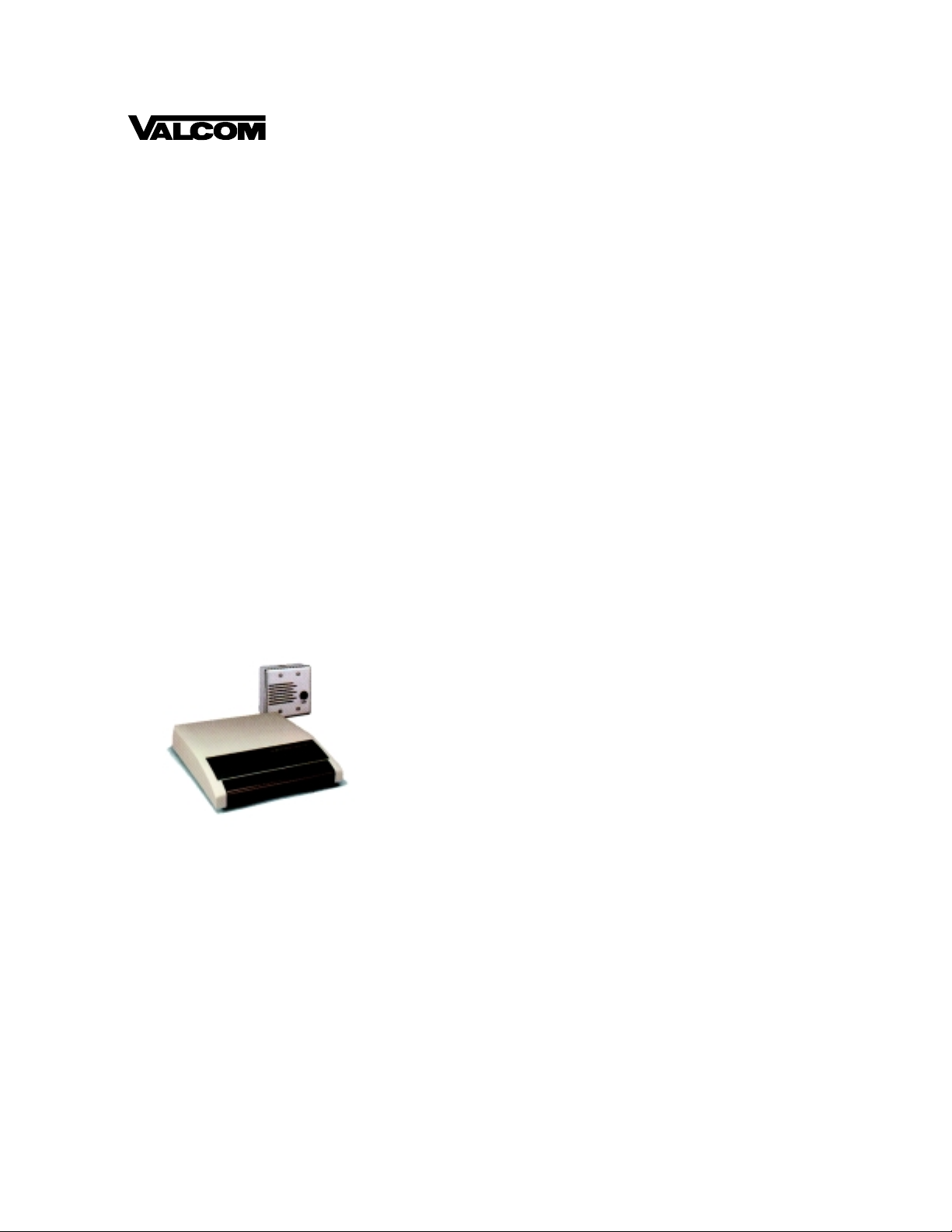
The PagePac® Door Phone Controller
The Door Phone Controller provides multi-functional control for
communications to a dedicated door-speaker unit and a remote doorunlocking device. The Door Phone Controller (see Figure1-1) can be used
alone, or it can be used along with a PBX (Private Branch Exchange) or
communications system to alert personnel within a residence or building
that someone is requesting attention at the entrance. Operating the unit is
simple: when the push button on the door speaker is pressed, the Door
Phone Controller unit signals a telephone station(s) and can activate an
auxiliary alerting device (such as a door bell, chime, or tone generator)
within the home or building. Upon hearing the ringing telephone and/or
alerting device, answer the phone and have a two-way phone conversation
with the person at the door. The person inside the building can also
remotely unlock the door, either by entering a numeric code (Door Code)
on the telephone's touch-tone keypad, or by pressing a button.
Features
■ Control for remote door unlocking
■ Voice communications with door speaker
■ Door ajar detect
■ Interface for door bell, chime, or tone generator
■ Selectable option functions (from touch tone telephone)
Introduction 1-3
Page 8
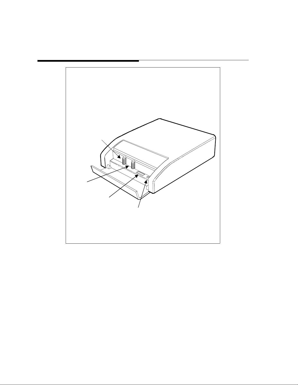
SPEAKER
VOLUME
TALK BACK
VOLUME
DIP SWITCHES
DIP SWITCH
LED
Figure 1-1. Front View of the PagePac® Door Phone Controller and
Control Panel
1-4 Introduction
Page 9

Terms You Should Know
Auxiliary Alert—A door speaker's push button can activate a
bell/chime within the building.
Cadence—Telephone Ringing cycle, i.e., 2 second ringing,
4 second no ringing.
C.O. line—Central Office telephone line carrier into building.
EKTS (Electronic Key Telephone System)—Small business telephone
communications system.
Ground Start—One method b y whi ch a busi ness teleph one s ystem (PBX )
signals the telephone company that you have gone off-hook. Used in most
business applications – contact your telephone company to determine if
you have Gr ound or Loop Start.
Loop Start—One method of signaling the telephone company that your
telephone has gone off-hook – used for most residential and
communication system applications. Contact your telephone company to
determine if you have Ground or Loop Start.
PBX (Private Branch Exchange)—Business telephone system.
Ringdown—In Station mode, the activation of the door speaker's push
button will cause the Door Phone Controller to dial the number of a
predetermined telephone st ation number (PBX or EKTS must be ins talled).
When the telephone is answered, there is direct two-way communication
with the door speaker.
Trunk Port—PBX connection for Central Office or trunk lines.
Station Port—PBX connection for station sets.
Hook-Flash—This causes telephone equipment to go “on hook” for a
duration usually less than a second (not long enough to be considered as
calling for the circuit to be released.)
Introduction 1-5
Page 10

Installation Procedures
Contents
Important Safety Instructions 2-2
General Information 2-4
Introduction 2-5
Door Phone Controller Back Panel Connections 2-5
Prior To Installation 2-7
Door Phone Controller Location 2-8
Installation 2-10
■ Mounting Instructions 2-10
■ Wall Mount Instructions 2-10
Connecting Door Speaker, Door Button,
and Door Ajar Switch to the Door Phone Controller 2-12
■ Remote Door Open Switch (Optional) 2-12
2
■ Electric Door Strike Plate Device (Optional) 2-14
■ Auxiliary Alert Device (Optional) 2-16
Connecting Power 2-17
Operation and Controls Information 2-18
■ Door Ajar Function 2-18
■ Speaker Volume Contro l 2-18
■ Talk Back Volume Control 2-18
■ LED 2-19
Connecting the Door Phone Controller
to Your Telephone Equipment 2-20
2-1 Installation Procedures
Page 11

Important Safety Instructions
When using your telephone equipment, basic safety precautions should
always be followed to reduce the risk of fire, electric shock and injury to
persons, in cluding the following:
1. Read and understand all instructions.
2. Follow all warnings and instructions marked on the product.
3. Unplug this product from the wall outlet before cleaning. Do not use
liquid cleaners or aerosol cleaners. Use a damp cloth for cleaning.
4. Do not use this product near water , for example, near a bath tub, wash
bowl, kitchen sink, or laundry tub, in a wet basement, or near a
swimming pool.
5. Do not place this product on an unstable cart, stand, or table. The
product may fall, causing serious damage to the product.
6. Slots and openings in the cabinet and the back or bottom are provid ed
for ventilation. To avoid overheating, these openings must not be
blocked or covered. The openings should never be blocked by
placing the product on the bed, sofa, rug, or other similar surface.
This product should never be placed near or over a radiator or heat
register. This product should not be placed in a built-in installation
unless proper ventilation is provided.
7. This product should be operated only from the type of power source
indicated on the marking label. If you are not sure of the type of
power supply to your home, consult your dealer or local power
company.
Install at i on P rocedures 2-2
Page 12

8. WARNING: RISK OF ELECTRICAL SHOCK –
EQUIPMENT MUST BE PROPERLY GROUNDED. Your
PagePac
®
equipment requires a pr operly gr ounded three-p rong
power receptacle for safe operation. Have the receptacle
checked by a qualified electrician before connecting this
equipment. Do not cu t or rem ove the t hird (grou nd) p rong from
the power transformer. Do not use two-prong extension cords
or adapters to defeat the safety features of this equipment. If
you have a two-prong receptacle, it must be replaced with a
three-prong receptacle, installed by a qualified electrician.
9. Do not allow anything to rest on the power cord. Do not locate this
product where the cord will be abused by persons walking on it.
10. Do not overload wall outlets and extension cords as this can result in
the risk of fire or electric shock.
11. Never push objects of any kind into this pr oduct throug h cabinet slots
as they may touch dangerous voltage points or short out parts that
could result in a risk of fire or electric shock. Never spill liquid o f any
kind on the product.
12. To reduce the risk of electric shock, do not disassemble this product,
but take it to a qualified serviceman when some service or repair
work is required. Opening or removing covers may expose you to
dangerous voltages or other risks. Incorrect reassembly can cause
electric shock when the appliance is subsequently used.
2-3 Installation Procedures
13. Unplug this product from the wall outlet and refer servicing to
qualified service personnel under the following conditions:
A. When the power supply cord or plug is damaged or frayed.
B. If liquid has been spilled into the product.
C. If the product has been exposed to rain or water.
Page 13

D. If the product does not operate normally by following the
operating instructions. Adjust only those controls that are
covered by the operating instructions, because improper
adjustment of other controls may result in damage and will
often require extensive work by a qualified technician to
restore the product to normal operation.
E. If the product has been dropped or the cabinet has been
damaged.
F. If the product exhibits a distinct change in performance.
14. Avoid using a telephone (other than a cordless type) during an
electrical storm. There may be a remote risk of electric shock from
lightning.
15. Do not use the telephone to report a gas leak in the vicinity of the
leak.
SAVE THESE INSTRUCTIONS.
General Information
Please adhere to the following precautions:
1. Never install telephone wiring during a lightning storm.
2. Never install telephone jacks in wet locations unless the jack is
specifically designed for wet locations.
3. Never touch uninsulated telephone wires or terminals unless the
telephone line has been disconnected at the network interface.
4. Use caution when installing or modifying telephone lines.
Installation Procedures 2-4
Page 14

Introduction
Note: Contact a
licensed electricia n for
installation of optional
devices such as an
electric strike plate and
auxiliary alert device
which may require
electrical wiring. For
the electric strikeplate,
a low voltage device
(24 volts or less) is
recommended.
This section provides instructions for installing your PagePac® Door Phone
Controller. Provided are installation instructions for an optional electric door
strike plate, door ajar contacts, and an auxiliary alert device. These optional
components must be installed prior to the installation of your Door Phone
Controller. (Refer to the respective installation manu als for specific mounting
and wiring instructions.) The flow-chart provided in Figure 2-9, will help
direct you to the next appropriate section for attaching the Door Phone
Controller to the telephone equipment in your home or business (also see
Compatibility Chart on page iii).
Inside the Door Phone Controller shipping carton you will find:
■ The Door Phone Controller unit.
■ Mounting template (along the edge of the Quick Reference Chart).
■ Power cord and attached transformer.
■ T w o moun t ing screws .
■ Two 6-conductor modular-to-modular 6 foot long cables.
■ Terminal strip connector.
■ Instruction Manual (t his manual).
Door Phone Controller Back Panel Connections
Note: The 14-contact
terminal strip can be
unplugged from the
back panel.
*Note: The Canadian
equivalent of the RJ 11C
connector is CA11A.
Where applicable,
CA11A is to be
understood for
references to RJ11C in
this manual.
2-5 Installation Procedures
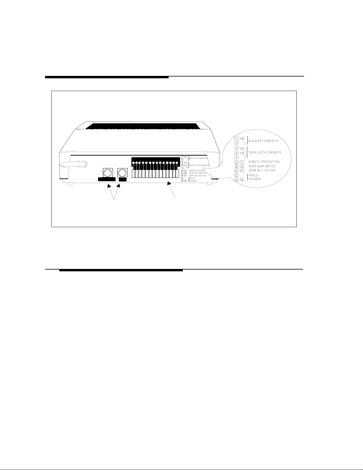
The Door Phone Controller back panel (see Figure 2-1) has two RJ11*
modular connectors and one 14-contact “hard wire” terminal strip. These
connections provide:
■ Auxiliary Alert Contacts (2) – output to optional door bell/chime
device.
■ Door Latch Contacts (3) – output to an electric door strike.
■ Remote Open Button Contacts (2) – input from a remote (inside) door
open button.
■ Door Ajar Switch Contacts (2) – input from door ajar device.
Page 15

■ Door Bell Button Contacts (2) – input from door bell/chime button.
■ Shield Contact (1) – used for shielding audio speaker wires.
■ Speaker Contacts (2) – provides audio connection to door speaker(s).
Host system RJ11 (J1 Host) modular jack interface—This jack is
provided for connection to your own telephone set, or business telephone
system (PBX or EK TS) (the host system).
Central Office RJ11 (J2) modular jack interface—This jack is provided
for connection to a C.O. telephone line (from telephone company's central
office).
WARNING: RISK OF ELECTRICAL SHOCK —
EQUIPMENT MUST BE PROPERLY GROUNDED. Your
PagePac
power receptacle for safe operation. Have the receptacle checked
by a qualified electrician before connecting this equipment. Do not
cut or remove the third (gro und) prong from t he power t ransformer.
Do not use two-prong extension cords or adapters to defeat the
safety features of this equipment. If you have a two-prong
receptacle, it must be replaced with a three-prong receptacle,
installed by a qualified electrician.
®
equipment requires a properly grounded three-prong
Installation Procedures 2-6
Page 16
12 VAC
60 Hz
1 AMP
SERIAL NO.
J2
TO
CENTRAL
OFFICE
J1
TO
HOST
SYSTEM
PAGEPAC DOOR PHONE
CONTROLLER
BACK PANEL
J3 TERMINAL BLOCK CONNECTION
1 2 3 4 5 6 7 9 10 11 12 13 148
REF. NO. 22050-055
RJ11
CONNECTORS
Figure 2-1. Door Phone Controller Back Panel Connections
Prior To Installation
Consider the following items before installation:
1. Never install telephone wiring during a lightning storm.
2. Never install telephone jacks in wet locations unless the jack is
specifically designed for wet locations.
3. Never touch uninsulated telephone wires or terminals unless the
telephone line has been disconnected at the network interface.
4. Use caution when installing or modifying telephone lines.
14-PO SIT IO N
TERMINAL STRIP
(REMOVABLE)
2-7 Installation Procedures
Page 17

PagePac® Door Phone Controller Location
You need to determine exactly where you want the unit installed and how
you want it configured. Another consideration is what components will be
used with the Door Phone Controller. Here are some questions that must be
answered prior to installation:
■ Do you currently have a door speaker installed?
■ Do you have a business telephone system (PBX or EKTS)?
■ Do you have a remote door unlock mechanism (electric door strike)
installed?
■ Do you have an auxiliary alert system (door chime) currently installed?
■ Do you have a door ajar switch installed?
The Door Phone Controller is designed to control the functions of the
components mentioned above, and how you answer these questions will
determine how the Door Phone Controller will be installed, optioned, and
operated.
When selecting options for your Door Phone Contro ller , e.g., to change the
door-unlock security code, the Door Phone Controller unit must be DIP
switch selected to Option Selection mode. For this reason y ou may want to
install the Door Phone Controller unit in a secure area which has access
only by authorized personnel. If you are installing the unit in a business
environment (currently have PBX/EKTS), you may wish to install the unit
along with the telephone equipment. (See Figure 2-2 for a typical
installation diagram.)
Install at i on P rocedures 2-8
Page 18
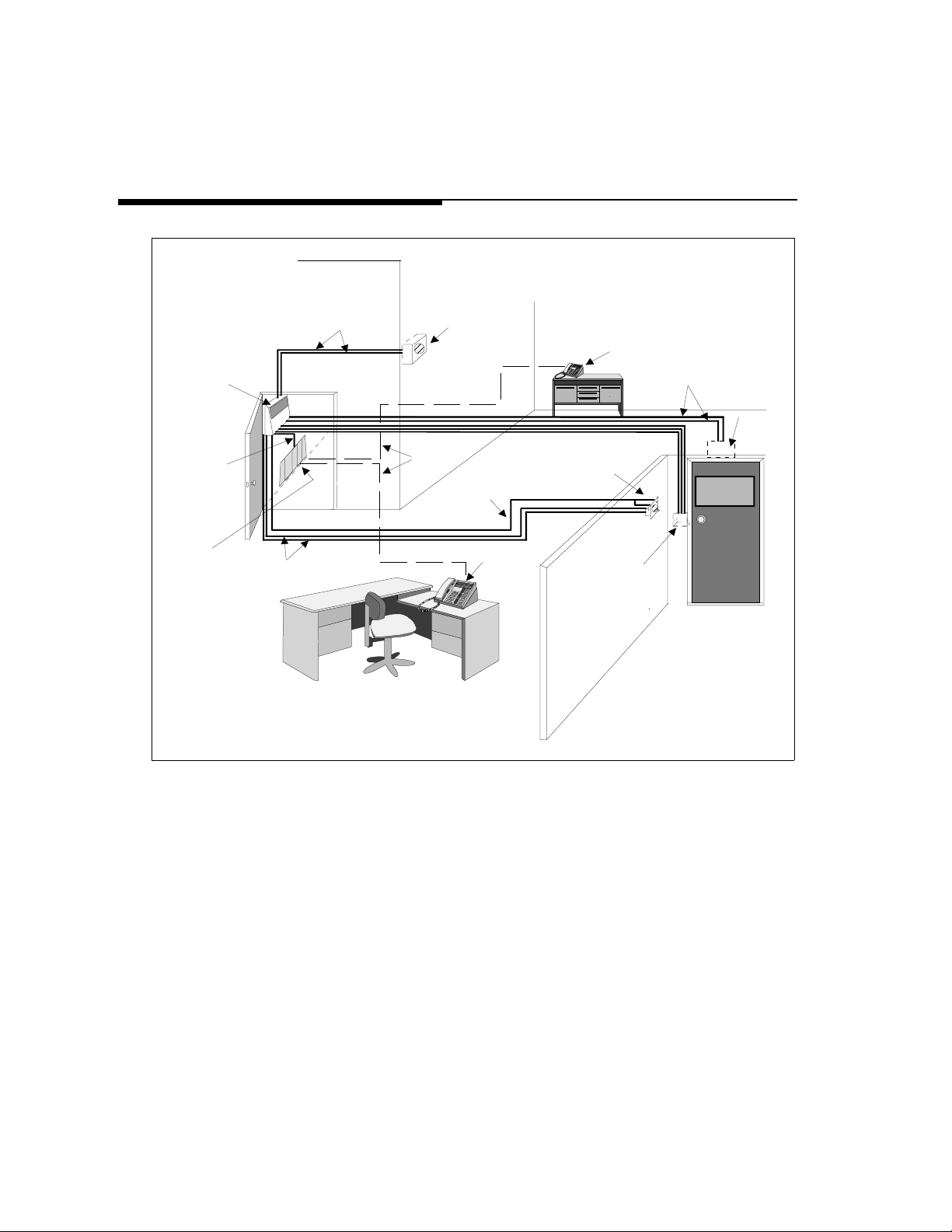
DOOR PHONE
CONTROLLER
(Secure Location)
22-24 GAUGE
WIRE
AUX. ALERT DEVI CE
TELEPHONE EXTE NSION
22-24 GAUGE
WIRE
DOOR AJAR
SWITCH
MODULAR
PHONE CABLE
TELEPHONE
EQUIP.
22-24 GAUGE
WIRE
EXISTING
PHONE
LINES
SHIELDED TWISTED
PAIR SPEAKER
WIRES
ATTENDENT
POSITION
DOOR SPEAKER
W/ PUSH BUTTO N
ELECTRIC
DOOR STRIKE
PLATE DEVICE
Figure 2-2. Typical PagePac® Door Phone Controller Installation
ENTRANCE
2-9 Installation Procedures
Page 19

Installation
Mounting Instructions
The Door Phone Controller can be placed on a flat table or shelf, or
mounted to a wall.
Wall Mount Instructions
The Door Phone Controller is shipped with a keyhole mounting template
and mounting screws. Follow the steps below to mount the Door Phone
Controller to a wall.
Note: When moving
Door Phone Con tr oller
or adding/ removing
cables from back panel,
unplug transformer
from 120V outlet.Also
unplug the terminal
strip and modular
phone connectors on
the back panel.
1. Place template (tear-out page at end of manual) over desired wall
mounting location and mark screw positions.
2. Use a Philips screwdriver to screw each of the two screws into the
marked screw positions.
IMPORTANT: Do not drive screws all the way into wall; adequate
space (5/16") must be left to position the Door Phone Controller bottom
panel keyholes over screw heads.
3. Mount th e Door Phone Controller ove r the protruding screw heads and
seat unit firmly to the wall. See Figure 2-3.
WARNING: RISK OF ELECTRICAL SHOCK —
EQUIPMENT MUST BE PROPERLY GROUNDED. Your
PagePac
power receptacle for safe operation. Have the receptacle checked
by a qualified electrician before connecting this equipment. Do not
cut or remove the third (gro und) prong from t he power t ransformer.
Do not use two-prong extension cords or adapters to defeat the
safety features of this equipment. If you have a two-prong
receptacle, it must be replaced with a three-prong receptacle,
installed by a qualified electrician.
®
equipment requires a properly grounded three-prong
Install at i on P rocedures 2-10
Page 20
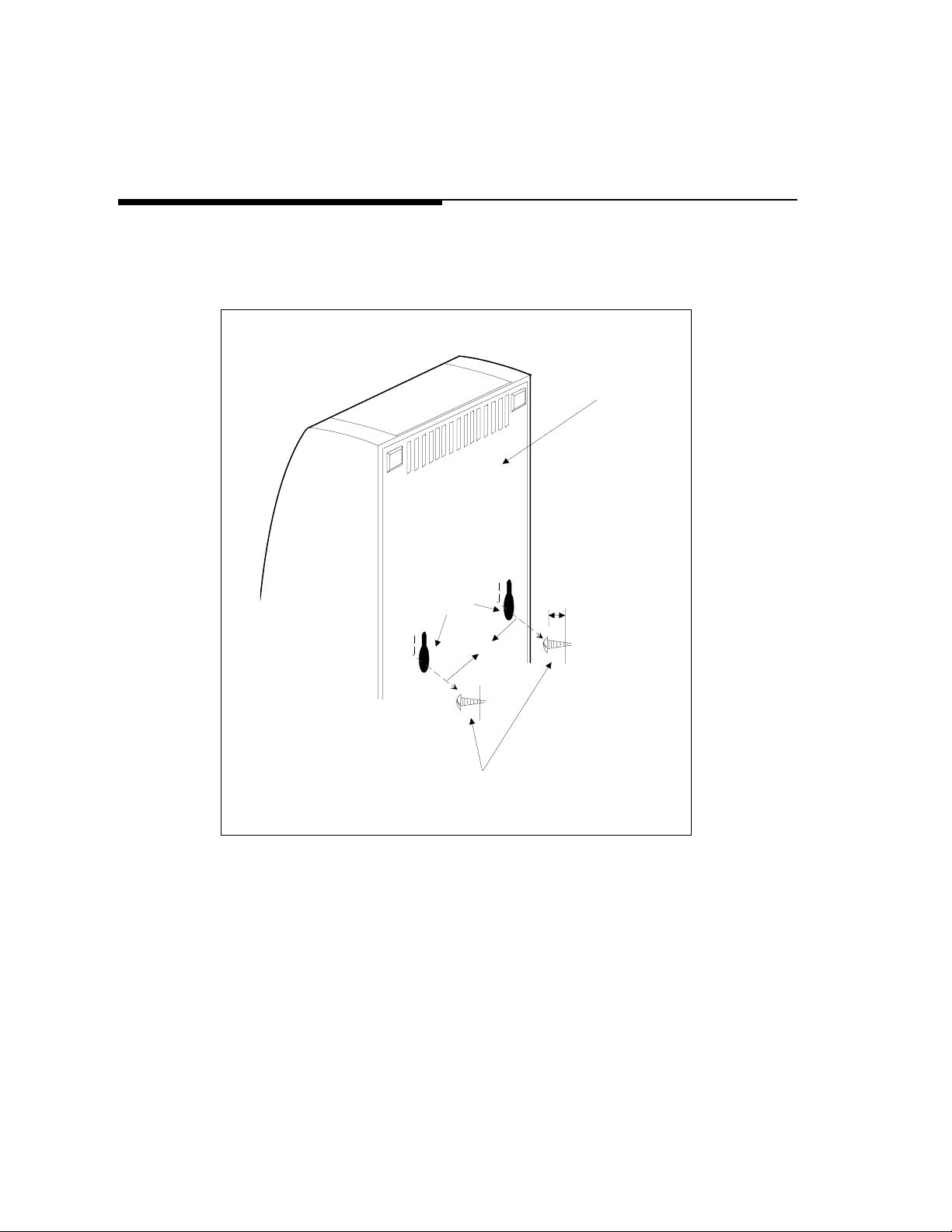
4. When the Door Phone Controller is securely mounted to the wall,
then all cables and wires can be connected to the terminal strip and
then plugged into the back panel.
DOOR PHONE
CONTROLLER
BACK PANEL
KEYHOLE
MOUNTING
SLOTS
8.1''
5/16'' TYPICAL
Figure 2-3. Mounting PagePac® Door Phone Controller to Wall
2-11 Installation Procedures
MOUNTING SCREWS
Page 21

Connecting Door Speaker, Door Button,
and Door Ajar Switch to the Door Phone Controller
Use the diagram in Figure 2-4 and follow the steps below:
Note: Polarity of wires
is not important.
Note: Total wire length
should not ex cee d 1500
feet.
Note: Door Ajar s witch
should be closed when
door is closed. If a door
ajar switch will not be
used, you must leave a
jumper installed across
the two “Door Ajar
Switch” terminals.
1. Run shielded twisted pair wires (22–24AWG) from the “Speaker”
terminals on the rear panel of the Door Phone Controller (13 and 14) to
the installed Door Speaker (1 and 2). Connect the shield to the “Shield”
terminal on the controller (12).
2. Run 2 wires (22–24AWG) from th e “Door B ell Bu tton” termi nals (1 0 &
11) to the door bell push button on the installed door speaker/push
button assembly (3 and 4).
3. Run 2 wires (22–24AWG) from the optional “Door Ajar Switch”
terminals (8 and 9) to the installed door ajar switch.
Remote Door Open Switch (Optional)
A remote door open switch (normally-open contact) provides additional
means for opening an electric door opening device. To connect wires for a
remote door open switch use the diagram in Figure 2-5 and follow the
steps below.
1. Install the remote door open button in desired location using
manufacturer's installation instructions.
2. Run 2 wires (22–24A WG) from t he installe d (normally -open contact )
remote door open switch to the “Remote Door Open” terminals (6
and 7) on the Door Phone Controller back panel (polarity of wires is
not important).
Install at i on P rocedures 2-12
Page 22
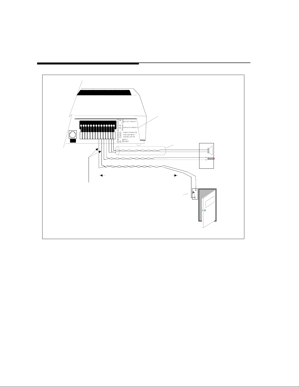
DOOR PHONE
CONTROLLER BACK PANEL
J3 TERMINAL BLOCK CONNECTION
J1
TO
HOST
SYSTEM
1 2 3 4 5 6 7 9 1011 1213148
1 2 3 4 5 6 7 9 1011 121 3 148
REF. NO. 22050-055
SHIELDED, TWISTED PAIR, 24 AWG.
DOOR SPEAKER
WITH PUSH BUTTON
1
2
3
4
APPROX. 1500 FT . MAXI MUM LENGTH
JUMPER THE TWO DOOR AJ AR SWITCH TERMINALS
IF DOOR AJAR DEVICE IS NOT USED
DOOR AJAR SWITCH
NOTE: MAGNETIC SWITCH
IS CLOSED WHEN DOOR
IS CLOSED
Figure 2-4. Connections for PagePac® Door Phone Speaker,
Door Button and Door Ajar Devices
2-13 Installation Procedures
Page 23
DOOR PHONE
CONTROLLER BACK PANEL
J1
TO
HOST
SYSTEM
J3 TERMIN AL BLOCK CONN ECTION
1 2 3 4 5 6 7 9 1011 1213 148
1 2 3 4 5 6 7 9 10 11 1213 148
REF. NO. 22050-055
MOMENTARY
PUSH BUTTON
NORMALLY OPEN
Figure 2-5. Connections for Remote Door Open Switch (optional)
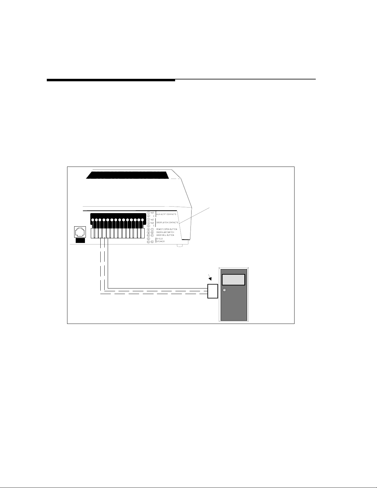
Electric Door Strike Plate Device (Optional)
Note: If your Electric
Door Strike Plate has
more than a 1 Amp
current draw, then an
external relay
arrangement is
required.
An electric door strike plate is used to automatically open a closed or
locked door. A low-voltage device (24V or less) is recommended. The
Door Phone Controller can provide an open or closed contact when
requested to interface to and to operate your electric door strike plate
device. Once an electric door strike plate has been installed, it can be
controlled by the Door Phone Controller unit, either from entering the
appropriate digits from a touch tone phone or from the Remote Open
switch (push button).
Follow the steps below and refer to Figure 2-6 for wiring the door strike
plate device to the Door Phone Controller.
Installation Procedures 2-14
Page 24
Note: Do not include
strike plate wires within
the same cable as
others wires connecting
to the Door Phone
Controller.
J1
TO
HOST
SYSTEM
J3 TERMINAL BLOCK CO NNECTIO N
1 2 3 4 5 6 7 9 10 11 1213 148
1234567 910111213148
REF. NO. 22050-055
1. Have the electric door strike plate device installed as instructed by the
manufacturers installation manual. Check electric installation codes and
local ordinances for exact wiring requirements in your area.
2. Normally Open (N.O.), Normally Closed (N.C.), and Common (C.)
relay contacts are accessible at the Door Phone Controller terminal
block. Wire these to the door strike plate device and its power sou rce as
instructed by your manufact urer 's ins tal lation manual. If no instructions
exist, wire the above relay contacts to the existing do or op en button (s ee
#3 below).
DOOR PHONE
CONTROLLER BACK PANEL
ELECTRIC
DOOR STRIKE
PLATE DEVICE
WITH POWER
SOURCE
ENTRANCE
Figure 2-6. Connections for Electric Door Strike Plate (Optional)
2-15 Installation Procedures
3. Verify all connections when connecting the door strike contacts on
the Door Phone Controller to existing door open buttons. Make sure
of the following:
Page 25

Note: One or the other
will apply, not both.
■ The NO and C contacts are connected in parallel to a normally-open
button.
■ The NC and C contacts are connected in series to a normally-closed
button.
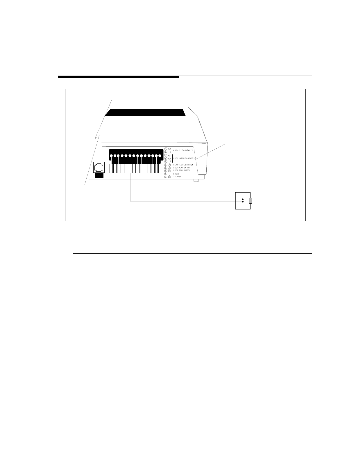
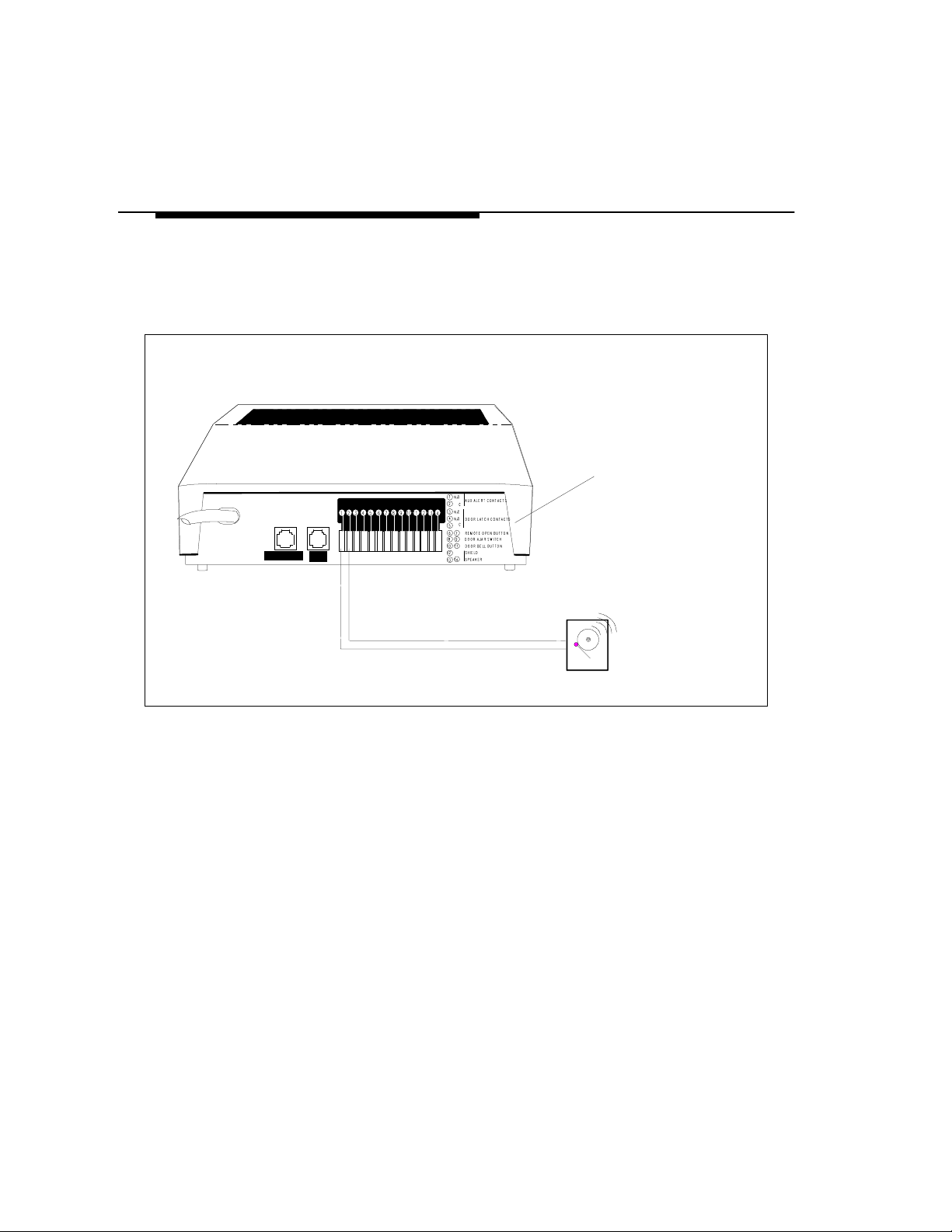
Auxiliary Alert Device (Optional)
Note: If the Auxiliary
Alert Device has more
than a 1 Amp draw,
then an external relay
arrangement will be
required.
Note: See Appendi x E
for specific auxiliary
alert device installation
information.
In most configurations, the Door Phone Controller will cause a telephone to
ring when the doorbell button is pushed. An auxiliary alert device (chime,
bell, horn, tone generator, etc.) can also be used as an alert to notify the
person inside the building that the doorbell button has been pushed (Auxiliary
Alert Mode). A low-voltage device (24V or less) is recommended. Follow the
steps below (refer to Figure 2-7) for wiring auxiliary alert device (door bell/
chime) to the Door Phone Controller:
1. Install the auxiliary alert device (door bell/chime) as instructed by the
manufacturer's installation manual.
2. The Normally Open (N.O.) and Common (C.) relay contact, located on
the Door Phone Controller back panel (see Figure
2-7), are accessible at the Door Phone Controller terminal block. Wire
these to the auxiliary alert device and it's power source as instructed by
the manufacturer's installation manual.
Installation Procedures 2-16
Page 26
Connecting Power
When the Door Phone Controller has been mounted to a wall or placed on
a shelf and all cables and wires have been connected to the back panel,
plug the transformer into a 120 VAC outlet. See Figure 2-8.
J2
J1
12 VAC
60 Hz
1 AM P
SERIAL NO.
TO
CENTRAL
OFFICE
SYSTEM
TO
HOST
J3 TERMINAL BLOCK CONNECTION
1 2 3 4 5 6 7 9 10 1112 13 148
REF. NO. 22050-055
DOOR PHONE
CONTROLLER
BACK PANEL
DOOR BELL/CHIME
(AUXILIARY ALERT
DEVICE) WITH POWER
SOURCE
Figure 2-7. Connections for Auxiliary Alert Device (Optional)
2-17 Installation Procedures
Page 27

Operation and Controls Information
Door Ajar Function
Default Condition—After the door has been o pened by the f our digit code
or the remote push button, the Door Phone Controller will wait for the
Door Ajar Call-back time-out to elapse. At this point if the door is still
open, the Door Phone Controller will call back the phone/chime for the
duration of the ring/chime duration and then repeat after the Door Ajar
Call-back time-out has elapsed again. If the phone is answered during that
time, a Door Ajar Tone will be heard. The Door Ajar Tone will cease when
any DTMF Digit is pressed, or the user speaks or hangs-up.
Alternate Condition—If the door is ever opened and the Door Ajar Callback time-out has elapsed, the Door Phone Controller will call back the
phone/chime for the duration of the ring/chime duration and then repeat
after the Door Ajar Call-back time-out has elapsed again. If the phone is
answered during that time, a Door Ajar Tone will be heard. The Door Ajar
Tone will cease when any DTMF digit is pressed, or the user speaks or
hangs-up.
Speaker Volume Control
Y o u can adjust the broadcast volume level of the door speaker by adjusting
the “Speaker Volume Control” on the Door Phone Controller front panel
(see Figure 1-1).
Talk Back Volume Control
You can adjust the reply volume level from the door speaker to an inside
telephone extension by adjusting the “Talk Back Volume Control” (see
Figure 1-1).
Install at i on P rocedures 2-18
Page 28

LED
When the PagePac® Door Phone Contro lle r is po wered on and func tioning
normally, the LED (Figure 1-1) should continually blink 2.5 times a
second. If there is a malfunction the LED will blink faster than 4 times a
second (see Troubleshooting section) or go out completely. If the LED is
not lit, check power to unit first before calling for repair.
2-19 Installation Procedures
Page 29

Connecting the Door Phone Controller to Your
START
NO
YES
YES
NO
YES
NO
REFER TO
SECTION 3
RESIDENTIAL INSTALLATION
REFER TO
SECTION 5
PBX WITH STATION PORT
REFER TO
SECTION 6
PBX WITHOUT DEDICATED
TRUNK OR STATION PORT
REFER TO
SECTION 4
PBX WITH DEDICATED
TRUNK PORT
*You must refer to your telephone system
owner manual for description of this
port.
Do
you have a
Business
Telephone
System
?
Spare
Trunk Port
Available*
?
Spare
Station Port
Available*
?
Telephone Equipment
Use the flow chart in Figure 2-9 to assist in configuring the Door Phone
Controller to your residential or business-type telephone equipment.
Answer each appropriate question in the flow chart and refer to the section
specified within this manual. Then proceed with the necessary installation
and option selection requirements. NOTE: If you are installing the Door
Phone Controller into a typical Home/Residential environment (no
PBX) refer to Section 3 now.
Figure 2-8. Configuration of Telephone Equipment Flow Chart
Install at i on P rocedures 2-20
Page 30

Installation for Home/Residential
(Trunk Saver Mode - Loop Start)
3
Contents
Overview 3-2
DIP Switch Selections 3-2
Installation 3-3
Option Selection 3-4
Operation – Basic Door Answer Function 3-6
■ Visitor Presses Door Speaker Button 3-6
■ Answering a Call from the Door Speaker 3-6
■ Calling the Door Speaker from Inside the Building 3-7
■ Telephone Line In Use When Visitor
Presses Door Speaker Button 3-7
■ Telephone Line In Use With Door When
Incoming C all Arrives 3-8
3-1 Installation — Home/Resid ential
Page 31

Overview
This section provides installation and operation information for
applications such as residences or small businesses which do not have a
telephone system.
Note: You may also use
the Door Phone
Controller with a
dedicated phone.
When your Door Phone Controller is installed with standard telephone
equipment (no PBX), the unit may operate in Shared Line Mode which
permits a single telephone set to be shared between the Door Phone
Controller and an outside line (to a Central Office). Thus, the standard
telephone equipment can be used for normal call operations as well as
servicing the door.
DIP Switch Selections
To customize the Door Phone Controller to your specific installation and
option requirements, you must properly set the 8 position DIP switch
located on the Door Phone Controller front panel (see Figure1-1).
CAUTION: Do not connect to the modular jacks on the Door
Phone Controller until after the DIP switches have been properly
set.
Note: Complete
information about the
DIP switch settings can
be found in Appendix A.
When using the Door Phone Controller with a small business or residential
telephone equipment (no PBX installed), the DIP switches must be set as
shown in Figure 3-1(all OFF).
LEGEND
On
Off
Figure 3-1. Home/Residential DIP Switch Settings
Installation — Home/Resid ential 3-2
Page 32

Installation
L
Note: When moving the
Door Phone Con tr oller
or adding or removing
cables from the back
panel, unplug the
transformer from 120V
outlet. Also unplug the
terminal strip and
modular phon e
connectors on the back
panel.
12 VAC
60 Hz
1 AMP
SERIAL NO.
TO C.O.
(Outside Line)
Connect the Door Phone Controller using the information in Section 2. Refer
to Figure 3-2.
DOOR PHONE CONTRO LLER
BACK PANEL
J1
J2
TO
CENTRAL
OFFICE
HOST
SYSTEM
TO
1 2 3 4 5 6 7 9 10 11 12 13 148
1 2 3 4 5 6 7 9 10 11 12 13 148
J3 TERM IN AL B LO C K C ON NECT ION
REF. NO. 22050-055
TO DOOR SPEAKER
TO DOORBELL BUTTON
TO DOOR AJAR SWITCH
TO REMOTE DOOR OPEN SWITCH
OPTIONA
TO DOOR STRIKE PLATE DEVICE
TO AUXILIARY ALERT DEVICE (DOOR BELL/CHIME)
TO TELEPHONES
Figure 3-2. Connecting PagePac® Door Phone Controller to Standard Telephone
Equipment
3-3 Installation — Home/R esidential
Page 33

Option Selection
Note: Refer to
Appendix B for a
detailed explanat ion of
each of these options.
The final step of the installation procedure is selecting options for your Door
Phone Controller. The selection of these options must be done while in the
Option Selection Mode. This mode lets you control such things as:
■ Delay Before Door Ajar Call-Back.
■ Ring/Chime Cadence.
■ Ring/Chime Duration.
■ Door Unlock Code.
■ Door Unlock Duration.
■ Enable Door Code.
■ Door Ajar Mode.
■ Forced Disconnect Time-Out.
■ Reset Options to Factory Defaults.
Follow the steps below to select options for the Door Phone Controller.
1. Select Option Selection Mode by setting position 8 of the Door
Phone Controller DIP switch to the ON position (see Figure 1-1).
2. Once the DIP switch has been set, you must make connection to the
door speaker by “hook-flashing” the phone (within 5 seconds) and
entering “##3” on the telephone keypad (option selection mode is
active as soon as you hear a distinctive dial tone).
Note: Any or all options
3. Use Table 3-1 to make each option selection.
may be reselected in
any order.
Table 3-1. PagePac® Door Phone Controller Option Selection Information
Options Mode Option Press
Delay Before Door
Ajar Call-back
Installation — Home/Resid ential 3-4
To Select Option 00 Single
To Verify 01
Listen
For
000 to 255 for 0 to 255 seconds of
Beep
delay after strike plate relea se stops
until Lucent Door Phone Controller
calls back to indi cate that door is ajar
Press Listen For Default
Double
Beep
30 sec.
Page 34

Table 3-1. PagePac® Door Phone Controller Option Selection Information
Options Mode Option Press
Ring/Chime
Cadence
Ring/Chime
Duration
Door Unlock Code To Select Option 30 Single
Door Unlock
Duration
Enable Door Code To Select Option 50 Single
Door Ajar Mode To Select Option 50 Single
Forced Disconnect
Time-Out
Reset Options to
Factory Defaults
Note: The Door Ajar De la y (Option Selection) will begin when the call to the door speaker is disconnected.
To Select Option 10 Single
To Verify 11
To Select Option 20 Single
To Verify 21
To Verify 31
To Select Option 40 Single
To Verify 41
To Verify 51
To Verify 51
To Select Option 60 Single
To Verify 61
To Select Option 70 Single
To Verify 71
Listen
For
24 (for 2 sec. on 4 sec. off cadence) or
Beep
15 (for 1 sec. on 5 sec. off cadence)
00 to 99 (0 to 99 second(s) ring/chime) Double
Beep
4 digits (first digit must be 0,3,4,5,6,7
Beep
or 8 remaining digits can be set from 0
to 9)
00 to 99 (door lock active time in sec.) Double
Beep
1 Enable door code
Beep
0 D isable door cod e
2 For callback after strike
Beep
Beep
Beep
plate release only
3 F or ca llback anytime
door is opened
010 to 255 (unit disconnects in 10 to
255 sec.)
## (to restore factory default
conditions)
Press Listen For Default
Double
Beep
Beep
Double
Beep
Beep
Double
Beep1(Enabled)
Double
Beep
Double
Beep
Double
Beep
2 sec./
4 sec.
30 sec.
6736
“OPEN”
4 sec.
2
120 sec.
N/A
3-5 Installation — Home/Resid ential
Page 35

Note: The Forced
Disconnect Timeout
option does not apply
when setting options
(unless 2 minutes
elapse without a T ou c hTone selection)
4. To exit option selection mode, press “##3” on the telephone keypad
(you will hear 2 beeps). Hang up the phone.
5. Set position 8 of the Door Phone Controller DIP switch back to the OFF
position.
Operation – Basic Door Answer Function
Vi sitor Pre sse s Door Spea ker Button
When a visitor presses the door speaker push button, the Door Phone
Controller will signal the telephone equipment inside your home or
building to ring, and activate a door-bell/chime device (optional). Any
additional presses on the door speaker push button will be ignored until the
option selected ring/chime duration has expired (with the exception that a
confirmation tone will still be sent to the speaker when the door button is
pressed).
Answering a Call from the Door Speaker
The person inside the building can simply answer the ringing phone and
establish two-way communications with the door speaker. To open the
door, the person inside the building either enters the Door Code on the
telephone's keypad or presses the customer provided door-unlock push
button. Either of these actions will activate the customer provided electric
door strike plate device.
As an alternative response when the telephone or door bell/chime is heard,
the person inside the building can press the door-unlock push button,
which will stop the ringing and will open the door. This allows the door to
be unlatched without the use of a phone.
Installation — Home/Residential 3-6
Page 36

Calling the Door Speaker from Inside the Building
To initiate a call to the door, the person within the building simply takes
the telephone off-hook and hook-flashes the telephone within the first 4
seconds. At this point, there will be direct two-way communication from
within the building to the door speaker.
Telephone Line In Use When Visitor
Presses Door Speaker Button
Note: Once the push
button is pressed, you
can “Hook Flash” to
the door speaker and
then back to the
original call only once,
unless the push button
is pressed again.
If you forget to hookflash back to the
original call, the Door
Phone Controller will
call you back.
If a visitor presses the door speaker button while an existing call is already
taking place on the C.O. line, the Door Phone Controller will generate a “door
alert” signal to indicate a visitor needs attention at the entrance. The person
inside the building can hook-flash the phone and be in direct two-way
communication to the door speaker. Then normal Door Phone Controller
functions can take place. When door phone functions have been completed,
i.e., door has been remotely opened, hook -flashing the pho ne again withi n the
forced disconnect timeout (or pressing 9) will return the line back to the
original call. This feature operates much like a call-waiting function.
Telephone Line In Use With Door When
Incoming Call Arrives
If there is a call in progress between the door speaker and a person inside
the building and a C.O. call comes in, the person inside the building (not
the door speaker) will hear a call waiting tone. The person inside the
building can hook-flash the phone (or dial 9) and communicate with the
incoming caller. When the call is complete, the person inside the building
hangs up the phone or to speak with the person at the door speaker again,
the person inside the build ing must hoo k-flash the phone (withi n 4 seconds
after picking up the receiver).
3-7 Installation — Home/Resid ential
Page 37

Installation for Telephone System With
Available Dedicated Trunk Port
4
Contents
Overview 4-2
DIP Switch Selections 4-2
Installation 4-3
Option Selection 4-6
Operation – Basic Door Answer Function 4-7
■ Visitor Presses Door Speaker Button 4-8
■ Answering a Call From the Door Speaker 4-8
■ Calling the Door Speaker 4-9
4-1 Installation With Dedicated Trunk Port
Page 38

Overview
This section provides installation and operation information for
installations with a telephone system that has an available Dedicated T r unk
port.
DIP Switch Selections
Note: Complete information
about the DIP switch settings
can be found in Appendix A.
Note: Use the Flow Chart in
Figure 4- 1 to properly set the
DIP switch.
To customize the PagePac® Door Phone Controller to your specific
installation and option requirements, you must properly set the 8-position
DIP switch located on the Door Phone Controller front Panel (see Figure 4-
1).
CAUTION:
Do not connect to the modular jacks on the Door Phone Controller
until after the DIP switches have been properly set.
When using the Door Phone Co ntro ller w ith a tel ephone sy stem wh ich ha s an
available dedicated trunk, set the DIP switch as shown in Figure 4-1. Prior to
setting this DIP switch, you must know if the dedicated trunk is Loop Start or
Ground Start; this information can be obtained from your local telephone
company.
Installation With Dedicated Trunk Port 4- 2
Page 39

LEG END
Off On
Figure 4-1. DIP Switch Setting for PBX with Dedicated Trunk Port
Installation
... T he C.O .
(T run k S av e r M o d e)
Imm edia tely
afte r cu t-thru
(D ia ling Tr u n k) to
Door Phone
Controller, what do
you w ant to
be connected
to...?
... T h e DO O R
(Port S aver M ode )
LOOP ST ART
LOOP START
1234 5 6 7 8
O N fo r
Option Selection
Mode Only
1234 5 6 7 8
Note: When moving the Door
Phone Controller or adding
or removing cables from the
To customize the Door Phone Controller use the information supplied in
Section 2 and the diagram in Figure 4-2. For ground start installations, also
see Figure 4-3. phone connectors on the back panel.
back panel, unpl ug
transformer fro m 120V outlet.
Also unplug the terminal strip
and modular cords.
Install the Door Phone Controller using the information supplied in Section 2
and the diagram in Figure 4-2. For ground start installations, also see Figure
4-3.
Complete information
regarding each DIP switch
position can be found in
Appendix A.
4-3 Installation With Dedicated Trunk Port
Page 40

M
DOOR PHONE
CONTROLLER BACK PANEL
J3 TERMINAL BLOCK CONNECT ION
1 2 3 4 5 6 7 9 10 11 12 13 148
1 2 3 4 5 6 7 9 10 11 12 13 148
MODE L NO . 22050-055
TERMINAL BLOCK "HARD
WIRE" CONNECTOR
TO DOOR SPEAKER
TO DOOR BELL BUTTON
TO DOOR AJAR SW ITCH
TO REMOTE DOOR OPEN SW ITCH
TO DOOR STRIKE PLATE DEVICE
TO AUXILIARY ALERT DEVICE (DOOR BELL/CHIME)
TRUNK PORT
TO C.O.
TO C.O.
TRUNK PORT
TRUNK PORT
OPTIONAL
TELEPHONE SYSTE
STATION
PORT
STATION
PORT
12 VAC
60 Hz
1 AMP
SERIAL NO.
NOT USED
NOTE: F o r Ground Start in s t a l lati o n s
see Figure 4-3.
Figure 4-2. Connecting Door Phone Controller to Standard Telephone Equipment
Installation With Dedicated Trunk Port 4-4
Page 41

TO DOOR PHONE CONTROLLER
J1 CONNECTORS
TO "SHIELD" TERMINAL (12) ON
DOOR PHONE CONTROLLER
COMMON
TELEPHONE SYSTEM
GROUND TERMINAL
TRUNK PO RT
TRUNK PO RT
TO C.O.
TRUNK PO RT
NOTE: For Ground Start installations:
Connect the green wire to Tip
and the red wire to Ring.
Figure 4-3. Ground Start Installations
STATION
PORT
STATION
PORT
TELEPHO NE SY STEM
4-5 Installation With Dedicated Trunk Port
Page 42

Option Selection
Note: Refer to Appendix B for
a detailed explanation of each
of these options.
The final step of the installation procedure is selecting options for your Door
Phone Controller. The selection of these options must be done while in the
Option Selection Mode. This mode lets you control such things as:
■ Delay Before Door Ajar Call-Back.
■ Ring/Chime Cadence.
■ Ring/Chime Duration.
■ Door Unlock Code.
■ Door Unlock Duration.
■ Enable Door Code.
■ Door Ajar Mode.
■ Forced Disconnect Timeout.
■ Reset Options to Factory Defaults.
Follow the steps below to select options for your Door Phone Controller.
CAUTION: Never connect a DOOR PHONE
CONTROLLER with the DIP Switches optioned for TRUNK
access to a STATION LINE! Doing so may cause damage to the
STATION LINE and/or the DOOR PHONE CONTROLLER!
1.Select Option Selection Mode by setting position 8 of the
Door Phone Controller DIP switch to the ON position (see Figur e
1-1).
2. Once the DIP switch has been set, you must make connection to the
door speaker by accessing the trunk connected to the Door Phone
Controller. At this point you must enter “##3” on the telephone keypad
(option selection mode is active as soon as you hear a distinctive dial tone).
Installation With Dedicated Trunk Port 4- 6
Page 43

Note: Any or all options may
3. Use Table 4-1 to make each option selection.
be reselected in any order.
The Forced Disconnect Timeout option does not app l y
4. To exit option selection mode, pre ss “##3” on the telephone key pad, you
will hear 2 beeps. Hang up the phone.
when setting options (unless 2
minutes elapse wit hout a
Touch-Tone selection).
5. Set position 8 of the Door Phone Controller DIP switch (Figure 1-1)
back to the OFF position.
Operation – Basic Door Answer Function
Table 4-1. Door Phone Controller O p tion
Selection Information
Options Mode Option Press
Delay Before Door
Ajar Call-back
Ring/Chime
Cadence
Ring/Chime
Duration
Door Unlock Code To Select Option 30 Single
Door Unlock
Duration
Enable Door Code To Select Option 50 Single
Door Ajar Mode To Select Option 50 Single
Forced Disconnect
Timeout
To Select Option 00 Single
To Verify 01
To Select Option 10 Single
To Verify 11
To Select Option 20 Single
To Verify 21
To Verify 31
To Select Option 40 Single
To Verify 41
To Verify 51
To Verify 51
To Select Option 60 Single
To Verify 61
Listen
For
Beep
Beep
Beep
Beep
Beep
Beep
Beep
Beep
Press
000 to 255 for 0 to 255 seconds of
delay after strike plate relea se stops
until Door Phone Controller calls ba ck
to indicate that door is ajar
24 (for 2 sec. on 4 sec. off cadence) or
15 (for 1 sec. on 5 sec. off cadence)
00 to 99 (0 to 99 second(s) ring/chime) Double
4 digits (first digit must be 0,3,4,5,6,7
or 8 remaining digits can be set from 0
to 9)
00 to 99 (door lock active time in sec.) Double
1 Enable door code
0 D isable door cod e
2 For callback after strike
plate release only
3 F or ca llback anytime
door is opened
010 to 255 (unit disconnects in 10 to
255 sec.)
Listen
For
Double
Beep
Double
Beep
Beep
Double
Beep
Beep
Double
Beep
Double
Beep
Double
Beep
Default
30 sec.
2 sec./
4 sec.
30 sec.
6736
“OPEN”
4 sec.
1
(Enabled)
2
120 sec.
4-7 Installation With Dedicated Trunk Port
Page 44

Table 4-1. Door Phone Controller Option
Selection Information (Continued)
Options Mode Option Press
Reset Options to
Factory Defaults
Note: The Door Ajar De la y (Option Selection) will begin when the call to the door speaker is disc onnected.
To Select Opti on 70 Single
To Verify 71
Listen
For
Beep
Press
## (to restore factory default
conditions)
Vi sitor Pre sse s Door Spea ker Button
When a visitor presses the door speaker push button, the Door Phone
Controller will signal the telephone equipment inside your building to ring
and activate a door-bell/chime (optional). Any additional presses on the
door speaker push button will be ignored (with the exception that a
confirmation tone will still be sent to the speaker when the door button is
pressed).
Answering a Call From the Door Speaker
When a person inside the building hear s the te lephone ri ng and/or t he door
bell/chime sound, he can simply respond by answering the ringing phone.
At this point, the Door Phone Controller will establish two-way
communication with the door speaker. To open the door, the person inside
the building either enters the Door Code on the telephone's keypad or
presses the door-unlock push button. Either of these actions will activate
the customer provided electric door strike plate device.
Listen
For
Double
Beep
Default
N/A
As an alternative response to hearing the telephone or door bell/chime, the
person inside the building can press the door-unlock push button which
will stop the ringing and will open the door. This allows the door to be
unlatched without the use of a phone.
Installation With Dedicated Trunk Port 4-8
Page 45

Calling the Door Speaker
T o initiate a call to th e Door Speaker, the person inside the building simply
takes the telephone off-hook and accesses the trunk connected to the Door
Phone Controller.
4-9 Installation With Dedicated Trunk Port
Page 46

Installation for PBX Equipment
With Available Station Port
5
Contents
Overview 5-2
DIP Switch Selections 5-2
Installation 5-3
Option Selection 5-5
Operation 5-7
■ Auxiliary Alert Mode – Basic Door Answer
Function 5-7
■ Ringdown Mode – Basic Door Answer Function 5-8
Installation With Available Station Port 5-1
Page 47

Overview
This section provides installation and operation information for
installations which use on-premise telephone system that has an av ailable
Dedicated Analog Station Port.
DIP Switch Selections
Note: Complete
information about the
DIP switch settings can
be found in Appendix A.
Note: Use the flow chart
in Figure 5-1 to prope rly
set the DIP switch.
To customize the Door Phone Controller to your specific installation and
option requirements, you must properly set the 8-position DIP switch
located on the Door Phone Controller front panel (see Figure 5-1).
CAUTION: Do NOT connect to the modular jacks on the
Door Phone Controller until after the DIP switches have been
properly set.
When using the Door Phone Controller with a telephone system which has
an available dedicated station port, set the DIP switch as shown in Figure
5-1. Prior to setting this DIP switch, you must know if the telephone
system is configured for auxiliary alert mode or ringdown mode (see page
1-5 for explanation of ringdown and auxiliary modes).
5-2 Installation With Available Station Port
Page 48

LEGEND
On
Off
AUX. ALERT
MODE
NO
START
Will you
configure your
telephone system
ON for
Opti on Selec tion
Mode On ly
for Ringdown
?
YES
RINGDOWN
MODE
Figure 5-1. DIP Switch Configuration for Telephone System with Dedicated Station
Access, Station Mode
Installation
Note: When moving the
Door Phone Con tr oller
or adding or removing
cables from the back
panel, unplug
transformer from 120V
outlet. Also unplug the
terminal strip and
modular phon e
connectors on the back
panel.
To customize the Door Phone Controller for this type of installation, you
must properly configure the 8-position DIP switch located on the Door Phone
Controller front panel (see Figure 1-1). Use the Flow Chart in Figure 5-1 to
properly set the DIP switch.
Installation With Available Station Port 5-3
Page 49

Install the Door Phone Controller using the information in Section 2. Refer
to Figure 5-2.
12 VAC
60 Hz
1 AM P
SERIAL NO.
NOT USED
J3 TERMINAL BLOC K C ONNECTION
1 2 3 4 5 6 7 9 10 11 12 13 148
1 2 3 4 5 6 7 9 10 11 12 13 148
MODEL NO . 22050-055
DOOR PHONE
CONTRO LLER BA CK PA NEL
TERMINAL BLOC K "H AR D
WIRE" CONNECTOR
TO DOOR SPEAKER
TO DOOR BELL BUTTON
TO DOOR AJAR SWITCH
TO REMOTE DOOR OPEN SWITCH
TO DOOR STRIKE PLATE DEVICE
TO AUXILIARY ALERT DEVICE (DOOR BELL/CHIME)
ANALOG
STATION PORT
OPTIONAL
TELEP HON E
SYSTEM
TO C.O.
TRUNK PORT
STATION
PORT
Figure 5-2. Connecting the PagePac® Door Phone Controller to a Telephone System with
Dedicated Analog Station Port
5-4 Installation With Available Station Port
Page 50

Option Selection
Note: Refer to Appendix
B for a detailed
explanation of each of
these options.
The final step of the installation procedure is selecting options for your
Door Phone Controller. The selection of these options must be done while
in the Option Selection Mode. This mode lets you control such things as:
■ Delay before Door Ajar Callback.
■ Ring/Chime Cadence.
■ Ring/Chime Duration.
■ Door Unlock Code.
■ Door Unlock Duration.
■ Enable Door Code.
■ Door Ajar Mode.
■ Forced Disconnect Time-Out.
■ Reset Options to Factory Defaults.
■ Phone Number Storage Memory 1.
■ Phone Number Storage Memory 2.
Follow the steps below to select options for the Door Phone Controller.
CAUTION: Never connect a DOOR PHONE
CONTROLLER with the DIP Switches optioned for TRUNK
access to a STATION LINE! Doing so may cause damage to the
STATION LINE and/or the DOOR PHONE CONTROLLER!
1.Select Option Selection Mode by setting position 8 of the
Door Phone Controller DIP switch (see Figure 1-1) to the ON
position.
2. Once the DIP switch has been set, you must make connection to the
door speaker by calling the extension number assigned to the Door
Phone Station Port. At this point you must enter “##3” on the
telephone keypad (option selection mode is active as soon as you
hear a dial tone).
Installation With Available Station Port 5-5
Page 51

Note: Any or all options
3. Use Table 5-1 to make each option selection.
may be reselected in
any order.
The Forced Disconnect
4. To exit option selection mode, press “##3” on the telephone keypad.
You will hear 2 beeps. Hang up the phone.
Time-out option d oes
not apply when setting
options (unless 2
5. Set position 8 of the Door Phone Controller DIP switch back to the OFF
position.
minutes elapse without
a Touch-Tone
selection).
Table 5-1. PagePac® Door Phone Controller Option Selection
Information
Options Mode Option Press
Delay Before Door
Ajar Callback
Ring/Chime Cadence To Select Option 10 Single
Ring/Chime
Duration
Door Unlock Code To Select Option 30 Single
Door Unlock
Duration
Enable Door Code To Select Option 50 Single
Door Ajar Mode To Select Option 50 Single
Forced Disconnect
Time-Out
Reset Options to
Factory Defaults
Phone Number
Stor ag e Memory 1
Phone Number
Stor ag e Memory 2
To Select Option
To Verify
To Verify 11
To Select Option 20 Single
To Verify 21
To Verify 31
To Select Option 40 Single
To Verify 41
To Verify 51
To Verify 51
To Select Option 60 Single
To Verify 61
To Select Option 70 Single
To Verify 71
To Select Option 80 Single
To Verify 81
To Select Option 90 Single
To Verify 91
Listen
For
00 Single
Beep
01
Beep
Beep
Beep
Beep
Beep
Beep
Beep
Beep
Beep
Beep
Press Listen For Default
000 to 255 for 0 to 255 seconds of
delay after strik e plate release stops
until Door Phone Controll er calls
back to indicate that door is ajar
24 (for 2 sec. on 4 sec. off cadence)
or
15 (for 1 sec. on 5 sec. off cadence)
00 to 99 (0 to 99 second(s) ring/
chime)
4 digits (first digit must be 0,3,4,5,6,7
or 8 remaining digits can be set from
0 to 9)
00 to 99 (door lock active time in
sec.)
1 Enable door code
0 D isable door cod e
2 For callback after strike
plate release only
3 F or ca llback anytime
door is opened
010 to 255 (unit disconnect s in 10 t o
255 sec.)
## (to restore factory default
conditions)
0 to 20 numerical digits and ✳ (✳
= 2 second pause) # terminates
entry
0 to 20 numerical digits and
second pause) # terminates e ntr y
✳ (✳ = 2
Double
Beep
Double
Beep
Double
Beep
Double
Beep
Double
Beep
Double
Beep1(Enabled)
Double
Beep
Double
Beep
Double
Beep
Double
Beep
Double
Beep
30 sec.
2 sec./
4 sec.
30 sec.
6736
“OPEN”
4 sec.
2
120 sec.
N/A
#
#
5-6 Installation With Available Station Port
Page 52

Operation
Auxiliary Alert Mode – Basic Door Answer
Function
Visitor Presses
Door Speaker
Button
Answering a
Call Sent From
the Door
Phone
Note: The telephone
system must pass Touch
Tones to the station
port connected to the
Door Phone Con tr oller
in order for the Door
Code to be recognized.
Complete installation
instructions for adding
an Auxiliary Alert
option can be found in
Appendix E.
When a visitor presses the door speaker push button, the Door Phone
Controller will activate an auxiliary alert (door-bell/chime). Any additional
presses on the door speaker push button will be ignored (with the exception
that a confirmation tone will still be sent to the speaker when the door button
is pressed).
When a person inside the building hears the door bell/chime sound, he can
simply respond by dialing the Door Phone Controller station number. At this
point, the Door Phone Controller will establish two-way communications
with the door speaker.
To open the door, the person inside the building either enters the Door Code
on the telephone's k eypad or press es th e customer provi ded doo r -unlo ck push
button. Either of these actions will activate the customer provided electric
door release.
As an alternative response to hearing the door bell/chime, the person inside
the building can press the door-unlock push button which will stop the
auxiliary contacts and will open the door. This allows the door to be
unlatched without the use of a phone.
Calling the
Door Speaker
To initiate a call to the Door Speaker, the person inside the building simply
takes the telephone off-hook and dials the station phone number of the door
speaker.
Installation With Available Station Port 5-7
Page 53

Ringdown Mode – Basic Door Answer Function
Visitor Presses
Door Speaker
Button
Answering a
Call Sent From
the Door
Phone
Note: Opening door
will terminate station
mode access.
Calling the
Door Speaker
When a visitor presses the door speaker push button, the Door Phone
Controller will activate a door-bell/chime (optional), go off-hook, and dial the
pre-selected stored phone number, 1 or 2 (these can be selected by pressing
##1 or ##2 once connection to the speaker has been made). Any additional
presses on the door speaker push button will be ignored while the Door Phone
Controller is off-hook.
When a person answers the ringing telephone, the Door Phone Controller will
establish two-way communications with the door speaker.
To open the door, the person inside the building either enters the Door Code
on the telephone's k eypad or press es the cus tomer provided door-unlock push
button.
Either of these actions will close the metallic contacts which activate the
customer provided electric door release.
To initiate a call to the Door Speaker, the person inside the building simply
takes the telephone off-hook and dials the station phone number of the door
speaker.
5-8 Installation With Available Station Port
Page 54

Installation for Telephone System
Without Available
Dedicated Trunk/Station Port
6
Contents
Overview 6-3
DIP Switch Selections 6-3
Installation 6-4
Option Selection 6-6
Port Saver or Trunk Saver Mode Installation 6-6
■ Port Saver Mode 6-6
■ Trunk Saver Mode 6-7
Operation – Basic Door Answer Function 6-9
■ Visitor Presses Door Speaker Button 6-9
■ Answering a Call From the Door Speaker 6-10
■ Calling the Door Speaker From Inside
the Building 6-10
Installation Without Dedicated Trunk/Station Port 6-1
Page 55

■ Telephone Line In Use When a Visitor
Presses Door Speaker Button 6-11
■ Telephone Line In Use With Door
When a Call Arrives 6-11
■ Placing a Call Through the C.O. From
Inside Building 6-12
6-2 Installation Without Dedicated Trunk/Station Port
Page 56

Overview
Note: Ground s tart trunks
will NOT operate
properly with this shared
trunk installation.
This section provides installation and operation information for
installations which use a telephone system that does not have an available
Dedicated Trunk or Station Port. By configuring the telephone system to
the instructions in this section, your telephone system equipment will
operate in Trunk/Port share mode.
DIP Switch Selections
Note: Complete
information about the
DIP switch settings can
be found in Appendix A.
To customize the Door Phone Controller to your specific installation and
option requirements, you must properly set the 8-position DIP switch
located on the Door Phone Controller front pan el (s ee Figure 1 -1) . Use the
flow chart in Figure 6-1 to help configure the DIP switch for either Trunk
Saver or Port Saver Mode.
A trunk shared with the Door Phone should never be configured in a
telephone system with other trunks in a common pool or group.
Installation Without Dedicated Trunk/Station Port 6-3
Page 57

LEGEN D
Off On
Figure 6-1. DIP Switch Setting for PBX With Shared Trunk Port
Installation
... The C .O.
(T run k S av e r M o d e)
Imm ediately
after cu t-thru
(D ia lin g T runk ) t o
Door Phon e
Controller, what do
you want to
be connected
to...?
... T h e DOO R
(Port Saver M o de)
LOOP ST AR T
LOOP ST AR T
1234 5 6 7 8
ON for
Option Selection
Mode O nly
1234 5 6 7 8
Note: When moving the
Door Phone Controller
Install the Door Phone Controller using the information in Section 2. Refer to
Figure 6-2.
or adding or removing
cables from the back
panel, unplug
transformer from 120V
outlet. Also unplug the
terminal strip and
To customize the Door Phone Controller for this type of installation, you
must properly set the 8-position DIP switch located on the Door Phone
Controller front panel (see Figure1-1). Use the Flow Chart in Figure 6-1 to
properly set the DIP switch.
modular phon e
connectors on the back
panel. Complete
information regarding
each of the DIP switch
CAUTION: Do NOT connect to the modular jacks on the Door
Phone Controller until after the DIP switches have been properly
set.
positions can be found
in Appendix A.
6-4 Installation Without Dedicated Trunk/Station Port
Page 58

DOOR PHONE
CONTROLLER BACK PANEL
J3 TERMINAL BLO C K C ON NEC TIO N
1234567 9
1234567910 11 1213 14
10
12
11
13
8
8
MO DEL NO . 22050-055
TO AUXILIARY ALERT DEVICE (DOOR BELL/CHI ME)
14
TO DOOR BELL BUTTON
TO DOOR AJAR SWITCH
TO REMOTE DOOR OPEN SWITCH
TO DOOR STRIKE PLATE DEVICE
TERMINAL BLOCK "HARD
WIRE" CONNECTOR
TO DOOR SPEAKER
OPTIONAL
TELEPHONE
SYSTEM
TO C.O.
12 VAC
60 Hz
1 AMP
SERIAL NO.
(TELEPHONE LINE)
STATION
PORT
STATION
PORT
TO C.O.
TRUNK PORT
(LOOP ST ART )
TRUNK PORT
Figure 6-2. Connecting the PagePac® Door Phone Controller to a Telephone System Wit h
Shared Trunk Port
Installation Without Dedicated Trunk/Station Port 6-5
Page 59

Option Selection
Note: Refer to Appendix
B for a detailed
explanation of each of
these options.
The final step of the installation procedure is selecting options for your
Door Phone Controller. The selection of these options must be done while
in the Option Selection Mode. This mode lets you control such things as:
■ Delay Before Door Ajar Callback.
■ Ring/Chime Cadence.
■ Ring/Chime Duration.
■ Door Unlock Code.
■ Door Unlock Duration.
■ Enable Door Code.
■ Door Ajar Mode.
■ Forced Disconnect Time-Out.
■ Reset Options to Factory Defaults.
Port Saver or Trunk Saver Mode Installation
Refer to the following instructions for Port Saver Mode or Trunk Saver
Mode installation.
Port Saver Mode
Follow the steps below to set the Door Phone Controller for Port Saver
Mode.
CAUTION: Never connect a DOOR PHONE
CONTROLLER with the DIP Switches optioned for TRUNK
access to a STATION LINE! Doing so may cause damage to the
STATION LINE and/or the DOOR PHONE CONTROLLER!
6-6 Installation Without Dedicated Trunk/Station Port
Page 60

1. Select Option Selection Mode by setting position 8 of the Door
Phone Controller DIP switch (see Figure 1-1) to the ON position.
2. Access the trunk (allocated for the Door Phone Controller), and make
connection to the door speaker by dialing “1” or “2” within 4
seconds. At this point you must enter “##3” on the telephone keypad
(Option Selection Mode is active as soon as you hear a distinctive
dial tone – if you don't hear a distinctive dial tone, check to see if
switch 8 is DOWN).
3. Use Table 6-1 to make each option selection.
Note: Any or all options
may be reselected in
any order. The Forced
Disconnect Time-out
option does not apply
when setting options
(unless 2 minutes
elapse without a T ou c hTone selection).
4. To exit Option Selection Mode, press “##3” on the telephone keypad.
5. Set position 8 of the Door Phone Controller DIP switch back to the
T runk Saver Mode
Follow the steps below to set the Door Phone Controller for Trunk Saver
Mode.
You will hear 2 beeps. Hang up phone.
OFF position.
CAUTION: Never connect a DOOR PHONE
CONTROLLER with the DIP Switches optioned for TRUNK
access to a STATION LINE! Doing so may cause damage to the
STATION LINE and/or the DOOR PHONE CONTROLLER
1.Select Option Selection Mode by setting position 8 of the
Door Phone Controller DIP switch (see Figure 1-1) to the ON
position.
!
Installation Without Dedicated Trunk/Station Port 6-7
Page 61

2. Access the Trunk (allocated for Door Phone Controller) and make
connection to the door speaker by “Hook-Flashing” the phone. At
this point you must enter “##3” on the telephone keypad (Option
Selection Mode is active as soon as you hear a distinctive dial tone –
if you don't hear a distinctive dial tone, check to see if switch 8 is
DOWN).
3. Use Table 6-1 to make each option selection.
Note: Any or all options
may be reselected in
4. To exit Option Selection Mode, press “##3” on the telephone keypad,
you will hear 2 beeps. Hang up phone.
any order. The Forced
Disconnect Time-out
option does not apply
5. Set position 8 of the Door Phone Controller DIP switch back to the
OFF position.
when setting options
(unless 2 minutes
elapse without a T ou c hTone selection).
Table 6-1. PagePac® Door Phone Controller Option Selection Information
Options Mode Option Press
Delay Before Door
Ajar Call-back
Ring/Chime
Cadence
Ring/Chime
Duration
Door Unlock Code To Select Option 30 Single
Door Unlock
Duration
Enable Door Code To Select Option 50 Single
Door Ajar Mode To Select Option 50 Single
To Select Option 00 Single
To Verify 01
To Select Option 10 Single
To Verify 11
To Select Option 20 Single
To Verify 21
To Verify 31
To Select Option 40 Single
To Verify 41
To Verify 51
To Verify 51
Listen
For
Beep
Beep
Beep
Beep
Beep
Beep
Beep
000 to 255 for 0 to 255 seconds of delay
after strike plate release stops until
Door Phone Controller ca l ls ba ck to
indicate that door is ajar
24 (for 2 sec. on 4 sec. off cadence) or
15 (for 1 sec. on 5 sec. off cadence)
00 to 99 (0 to 99 second(s) ring/chi m e) Double
4 digits (first digit must be 0,3,4,5,6,7
or 8 remaining digits can be set from 0
to 9)
00 to 99 (door lock active tim e in sec. ) Double
1 Enable door code
0 D isable door cod e
2 For callback after strike
plate release only
3 F or ca llback anytime
door is opened
Press Listen For Default
Double
Beep
Double
Beep
Beep
Double
Beep
Beep
Double
Beep1(Enabled)
Double
Beep
30 sec.
2 sec./
4 sec.
30 sec.
6736
“OPEN”
4 sec.
2
6-8 Installation Without Dedicated Trunk/Station Port
Page 62

Table 6-1. PagePac® Door Phone Controller Option Selection Information (Continued)
Options Mode Option Press
Forced Disconnect
Time-Out
Reset Options to
Factory Defaults
NOTE: The Door Ajar Delay (Option Selection) wil l be gi n w hen the call to the door speaker is disc onnected.
To Select Option 60 Single
To Verify 61
To Select Option 70 Single
To Verify 71
Listen
For
010 to 255 (unit disconnects in 10 to
Beep
255 sec.)
## (to restore factory default
Beep
conditions)
Press Listen For Default
Double
Double
Operation – Basic Door Answer Function
Vi sitor Pre sse s Door Spea ker Button
When a visitor presses the door speaker push button, the Door Phone
Controller will signal the telephone equipment inside your building to ring,
and activate an auxiliary alert (door-bell/chime) (optional). Any additional
presses on the door speaker push button will be ignored (with the
exception that a confirmation tone will still be sent to the speaker when the
door button is pressed).
Beep
120 sec.
N/A
Beep
Answering a Call From the Door Speaker
When a person inside the building hear s the te lephone ri ng and/or t he door
bell/chime sound, he can respond by answering the ringing phone. At this
point, the Door Phone Controller will establish two-way communication
with the door speaker. To open the door, the person inside the building
either enters the Door Code on the telephone's keypad or presses the
customer provided door-unlock push button. Either of these actions will
activate the customer provided electric door strike plate device.
As an alternative response to hearing the telephone or door bell/chime, the
person inside the building can press the door-unlock push button which
will stop the ringing and will open the door. This allows the door to be
unlatched without the use of a phone.
Installation Without Dedicated Trunk/Station Port 6-9
Page 63

Calling the Door Speaker From Inside
the Building
Note: Your PBX must
be capable of relaying
the hook-flash from the
station set to the trunk
port.
To initiate a call to the door in the Trunk Saver mode, the person within the
building simply takes the telephone of f-hook, accesses the trunk connected to
the Door Phone Controller, and hook-flashes the telephone within the first 5
seconds. At this point, there will be direct two-way communication from
within the building to the door speaker.
To initiate a call to the door in the Port Saver mode, the person within the
building simply takes the telephone of f-hook, accesses the trunk connected to
the Door Phone Controller, and dials “1” within the first 4 seconds. At this
point, there will be direct two-way communication from within the building
to the door speaker . (Alternatively, the person may dial a “9” within the first 4
seconds after accessing the trunk in order to be immediately connected to the
C.O. line.)
Telephone Line In Use When a Visitor
Presses Door Speaker Button
Note: Once the
doorbell push button is
pressed, you can
“Hook- Flash” to the
door speaker and then
back to the original call
only once, unles s the
push button is pressed
again.
If you forget to hookflash back to the
original call, the Door
Phone Controller will
call you back.
If a visitor presses the door speaker button while an existing call is already
taking place on the line, the Door Phone Controller will generate a “door
alert” signal to indicate a visitor needs attention at the entrance. The person
using the line can hook-flash the phone and be in direct two-way
communication to the door speaker. The other party will be placed on hold.
At this point, normal Door Phone Controller functions can take place. When
the door phone functions have been completed, i.e., door has been remotely
opened, hook-flashing phone again (or pressing 9) will return line to original
call. This feature operates much like a call-waiting function.
6-10 Installation Without Dedicated Trunk/Station Port
Page 64

Telephone Line In Use With Door
When a Call Arrives
If there is a call in progress between the door speaker and a s tation user and
a call (C.O.) comes in, the person insid e the building (not the d oor speaker)
will hear a call waiting tone. The station user can hook-flash the phone (or
dial 9) and communicate with the incoming caller. When the call is
complete, the station user hangs up the phone. To speak with the door
phone again, the station user must either hook-flash the phone (within 4
seconds of picking up the receiver) if installed for Trunk Saver Mode or
dial “1” if installed for Port Saver Mode.
Placing a Call Through the C.O. From
Inside Building
To initiate a call through the C.O. in the Trunk Saver Mode, the person
within the building simply takes the telephone off-hook, accesses the trunk
connected to the Door Phone controller, and then dials the desired phone
number. This is normal procedure for placing an outside call.
To initiate a call through the C.O. in the Port Saver Mode, the person
within the building simply takes the telephone off-hook, then accesses the
trunk connected to the Door Phone Controller. At this point the caller will
hear a dial tone from the Door Phone Controller. Dialing a “9”, or waiting
4 seconds, will switch the caller to the C.O. and the regular phone number
is dialed.
Installation Without Dedicated Trunk/Station Port 6-11
Page 65

Troubleshooting and Technical Assistance
7
Contents
Troubleshooting Procedures 7-2
Technical Assistance 7-4
Troubleshooting and Maintenance 7-1
Page 66

Troubleshooting Procedures
Table 7-1. Troubleshooting Procedures
Tr ouble Possible Cause Possible Solution
LED “off” constantly. Check power connection. If power connection is good, then return
LED “on” constantly. Brown-out condition or software frozen. Unplug and plug back in.
LED blinking more than four times a
second.
Talkback volume, but no speaker
volume.
Speaker volume, but no talkback
volume.
No page or talkback volume. Shorted or open speaker lead
Unit disconnects after a certain time. Check forced disconnect time-out
Dial tone heard from the speaker. DIP switches incorrect for mode of
Cannot hear your own voice in
telephone ear piece.
Station mode seizes line then
disconnects before Door Phone
Controller is accessed.
Cannot access Door Phone Controller
in trunk saver mode.
Getting door-ajar callba ck w h en door
is actually c losed.
Getting door-ajar callba ck w h en door
ajar switch is not used.
Receive C.O. call waiting tone when
accessing the Door Phone Controller
but cannot dial and/or hook-flash to
connect to call.
Internal software error; m ay stil l work. Un plug and plug back in; if problem
Volume control turned down or DIP
switches incorr ectly set for mode of
operation.
Volume control turned down. Verify setting.
connection.
selection.
operation. Telephone system returns dial
tone after Door Phone goes on-hook.
DIP switch incorrect. Correct.
Plugged wires into wrong jack. Correct.
Forced disconnect time-out set to low. Enter Option Select io n Mode (##3), and
Station line plugged into J2. Correct, move to J1.
J1 and J2 swapped. Check conn ec ti ons a nd correct if
Bad door ajar switch. Fix or adjust.
Open door ajar switch wiring. Fix.
Missing jumper on terminal block. Jumper pi ns 8 & 9 of term ina l bloc k.
Door Phone Controller opt ioned for
dedicated mode instead of Trunk Saver
or Port Saver Mode.
PBX does not relay the hook- fl ash. Use in dedicated mode.
for repair.
continues return for repair.
Verify setting of controls and DIP
switches.
Remove short or open.
Change time-out (option se lection).
Verify Mode of operation. Program
telephone system for no dial tone on this
extension.
enter new Forced Disconn ec t Time-out
Duration.
needed.
Verify DIP switch positions.
7-2 Troubleshooting and Technical Assistance
Page 67

Table 7-1. Troubleshooting Procedures (Continued)
Tr ouble Possible Cause Possible Solution
Cannot open door remotely using
Touch Tone door unlatch function.
Cannot open door remotely using
remote door open button.
Cannot open door remotely using
either Remote Door Open Button or
the Door Code.
Selected options are not operating as
expected.
Door Unlock option disabled
or
Wrong Door Code.
Check all wiring from Do or Phone
Controller to electric strike plate device
(see manufacturer's instructio ns).
Check all wiring from Do or Phone
Controller to electric strike plate device,
also check operation of electric st ri ke
plate device (see manufacturer's
instructions).
Improper wiring to existing door strike
device. May be caused by i mproper
connection and use of NO (Norm allyOpen), NC (Normally Closed), and C
(Common) door latch relay contacts,
especially when interfacing these
contacts to existing door configurations.
Incorrect or inappropriate values were
entered.
If error tone, verify Door Open Code and
Door Unlock enable option.
Disconnect wires from the term i nal
block “Door Unlatch Con ta ct s . ” Us e
volt/ohm meter to check co ntinuity
between NO an d C terminals while
activating Touch-Tone door unlatch
function. If continuity test fails, re tur n
Door Phone Controller for re pa ir.
Disconnect wires from the term i nal
block “Remote Open Button” and “Door
Unlatch Con tacts.” Use volt /ohm meter
to check continuity between both w ire s
from the remote open button while
activating the button. If continuity test of
button is good, button is OK. N ow
reconnect button wires to “Re mote
Button Contacts,” and check continuity
of “Door Unlatch Contacts” (between
NO and C) while activating remote door
open button. If continuity test fails,
return Door Phone Controller for repair.
Verify all connections w he n connecting
the door strike contacts on t he Do or
Phone Controller to exis ting door open
buttons. Make sure of the follow i ng:
1. The NO and C contacts are connect ed
in parallel to a normal ly -open button.
2. The NC and C contacts ar e connected
in series to a normally-ope n but ton.
Use Verify mode to confirm selected
options without changing the values.
Carefully consider the “co n s equences”
of options chosen.
Troubleshooting and Technical Assistance 7-3
Page 68

Technical Assistance
When calling, have a VOM and a telephone test set available and call from
the job site. Call (540) 427-3900 and ask for PagePac Technical Support, or
call (540) 427-6000 fo r Valcom 24-hour Automated Su ppo rt or v isi t our web sites at http://www.pagepac.com and
www.valcom.com.
Should repairs be necessary, attach a tag to the unit clearly stating company
name, address, phone number , con tact person, an d the nature of the pr oblem.
Send the unit to:
PagePac
Roanoke, VA 24019-5056
®
Repair Dept.
Valcom, Inc.
5614 Hollin s Road
7-4 Troubleshooting and Technical Assistance
Page 69

Appendix A—DIP Switch Settings
Setting the DIP Switch Positions
Note: All switches are OFF
when shipped from the
factory.
The PagePac® Door Phone Controller's basic operating modes are selected on
the 8-position DIP switch at the front of the unit (see Figure 1-1). Positions 1
through 5 are used to set up the way the Door Ph one C ontr oller will interface
with your telephone equipment. Position 8 is used to access Option Selection
Mode. Positions 6 and 7 are not used. The definition of each switch position
is given below:
Switch 1
Selects between Trunk Access and Station Access. Trunk Access = OFF;
Station Access = ON.
Switch 2
Selects between Dedicated Trunk or Shared Trunk. This switch only has
meaning when Trunk Access is selected with Switch 1. Shared Trunk =
OFF; Dedicated Trunk = ON.
Switch 3
Selects between Trunk Saver or Port Saver. This switch only has meaning
when Trunk Access is selected with Switch 1 and Shared Trunk is selected
with Switch 2. Trunk Saver = OFF; Port Saver = ON.
Switch 4
Selects between Loop Start and Ground Start. This switch only has
meaning when Trunk Access is selected with Switch 1. Loop Start = OFF;
Ground Start = ON.
Switch 5
Selects between Auxiliary Alert or Ringdown. This switch only has
meaning when Station Access is selected with Switch 1. Auxiliary Alert =
OFF; Ringdown = ON.
DIP Switch Settings A-1
Page 70

Switch 6
Not used.
Switch 7
Not used.
Switch 8
Selects between Option Selection Mode and Normal Operation. This
switch acts as a Option Selection security switch. If this switch is ON, any
user can activate Option Selection Mode by keying in “##3” on a touchtone telephone set which connects directly to the Door Phone Controller.
When this switch is OFF, Option Selection Mode cannot be activated.
Normal Mode = OFF; Option Selection Mode = ON.
A-2 DIP Switch Settin gs
Page 71

Appendix B—Option Selection Mode Definitions
Ring/Chime
Cadence
Ring/Chime
Duration
The information below provides detailed information regarding each of the
settable options for the PagePac
Provides an alternate ring (on/off) cycle from how it would ring for a
normal call. For instance, you can configure the telephone to ring for 2
seconds and then be silent for 4 seconds, or ring for 1 second and then be
silent for 5 seconds.
This option provides a maximum duration of teleph one ringing cycles (in
seconds) before the Door Phone Controller will disconnect.
®
Door Phone Controller.
Door Unlock Code This option determines what your door unlock combination will be. The
default is set for 6736, but for security reasons it is recommended you
change this to your own four-number combination.
Door Unlock
Duration
This option determines the amount of time the door unlock function will be
activated. The default is 4 seconds.
Enable Door Code This option can be set so the door access code is disabled. Once it is
disabled, entering the door unlock code will not provide a door unlock
function.
Door Ajar Mode This option provides the choice of either having the Door Ajar call back
any time the door is opened, or only after it has been opened via the strike
plate release. Note: When the Door Ajar switch senses that the door has
been opened and closed again, the door open relay will cease being
energized.
Forced Disconnect
Time-out
Reset Option
Selections to
Factory Defaults
This option sets the maximum time in which two-way communications can
take place between the door speaker and the telephone. Setting this option
to less than 30 seconds is not advised.
This option is useful when current option selections are unknown. Note
that this function will reset the Door Unlock Code to the default value, but
it will not reset “Phone Number Storage Memory 1” or “Phone Number
Storage Memory 2” (see below). Defaults to dialing phone number #1.
Option Selection Mode Definitions B-1
Page 72

Phone Number
Storage Memory 1
This option is used in what is called “Ringdown Mode” to auto-dial a
particular extension or outside-line phone number. The Door Phone
Controller has two memory locations for holding user stored telephone
numbers. Phone numbers can be for telephones within the same building or
off-premises. These memory locations are used exclusively in Ringdown
Mode. Only one memory location is active at a time. To select the active
location for the phone number, a telephone connection to the Door Phone
Controller must be made (by calling the extension number of the Door
Phone). Once connected dial in “##1”, this selects Memory Location 1; if
you were to dial in “##2”, you would select Memory Location 2.
Phone Number
Storage Memory 2
Delay Before Door
Ajar Call Back
See above explanation.
This option determines the length of time allowed for the door to shut after
it has been opened by the strike plate release. If the door is still ajar at the
end of this period, the controller will call back and an alarm tone will be
heard in the receiver when the phone is answered.
B-2 Option Selection Mode Definitions
Page 73

Appendix C—Spec ifications
Electrical
Standards The Door Answer Controller meets:
■ F.C.C. part 15, class B requirements.
■ F.C.C. part 68 requirements.
■ CSA/NRTL requirements.
Electrostatic
Discharge
Your Pag e Pac® Door Phone Controller complies with the ESD
requirements in BELL Pub 48002.
All user accessible connectors and controls have electrostatic discharge
protection.
Power Supply The Door Phone Controller is powered by an UL listed wall mount
transformer with a strain relieved cord.
It functions over an input power range of 96 VAC to 129 VAC.
Your Door Phone Controller has a green LED power indicator.
■ A flashing state of 2.5 per second indicates norma l power to the un it
and normal microprocessor operation.
■ A constant ON state indicates a brown-out condition or microprocessor
failure.
■ A constant OFF state indicates there is no power to the unit.
Page and TalkBack Amplifier
Paging output power is 2 watts (continuous) @ 3.35 Vrms (sine wave).
Talkback input sensitivity: with 600 microVrms at the speaker leads, tip
and ring output level will be -17 dBm.
Auxiliary Alert Relay Contact Closures rated at 1 amp.
Door Latch
Relay Contact Closures rated at 2 amps.
Contacts
Specifications C-1
Page 74

Ring Generator Your PagePac
®
Door Phone Controller provides a ring generator signal
which can ring devices th at respond to ei ther 20 Hz or 6 0 Hz frequencie s.
The ringer will automatically adapt to a 50 Hz line by ringing at 25 Hz.
A Ringer Equivalence (REN ) of 2 is supported by the Door Phone
Controller.
C.O. Line Jack Input has a REN of 0.5, Type B.
Mechanical
The Door Phone Controller's control unit PCB is mounted in a molded
plastic enclosure with a metal back panel. The front panel is protected by a
flip down cover. You have access to controls and connections on the front
panel and back panel.
Front Panel The front panel controls and indicators consist of:
■ One page volume control.
■ One talkback volume control.
■ One 8 position DIP switch.
■ One power indicator (green LED).
Back Panel The back panel connections consist of:
■ One strain relieved cord approximately 6 feet in length attached to a
wall mount transformer.
Note: The Canadian
equivalent of the RJ11C
connector is CA11A. Where
applicable, CA11A is to be
understood for reference to
RJ11C in this manual.
Dimensions and
Weight
C-2 Specifications
■ One RJ11* jack for the telephone/PBX interface.
■ One RJ11* jack for Central Office interface.
■ One connector mounted terminal strip.
Length: 10.5 inches, Width: 9.5 inches, Height: 2.5 inches,
W eight: 5.5 lbs.
Page 75

Appendix D—Using the Door Phone Controller
With An Answering Machine
Installation Information
Note: When configuring the
Door Phone Controller to
answer both the door and
telephone calls, be sure to
change your outgoin g
message accordingly.
This Appendix provides two methods for configuring an answering
machine to the PagePac
diagrams how to connect the Door Phone Controller with an answering
machine so that only regular telephone calls are answered by the
answering machine (see Figure A-1). The second method diagrammed will
allow the answering machine to answer both regular telephone calls and
calls from the Door Speaker (see Figure A-2).
®
Door Phone Controller. The first method
CAUTION: When using your answering machine to answer
both door and telephone calls, make sure to set your answering
machine to allow for a limited length incoming message. Do not
use an answering machine that cannot limit the incoming message
length.
Using With An Answering Machine D-1
Page 76

TYPICAL
ANSWERING MACHINE
TO TEL.
LINE JAC K
TO TEL.
SET JACK
TO J2
CONNECTOR
DOOR
PHONE CONTROLLER
(SHARED TRUNK MODE)
TO J1
CONNECT OR
J3 TERMINAL BLOCK CONNECTION
1 2 3 4 5 6 7 9 10 11 1213 148
1234567 910111213148
REF. NO. 22050-055
SERIAL N O.
12 VAC
60 Hz
1 AMP
TO PHONE C.O.
TELEPHONE OR
TELEP HO N E SY ST EM TRUN K
Figure D-1. Installation Method Used For Answering Only Telephone Calls
DOOR
TO J2
CONNECTOR
12 VAC
60 Hz
1 AMP
SERIAL N O.
PHONE CONTROLLER
(SHARED TRUNK MODE)
TO J1
CONNECTOR
J3 TERMINAL BLOCK CONNECTION
1 2 3 4 5 6 7 9 10 11 1213 148
1234 567 910111213148
MODEL N O. 22050-055
TYPICAL
ANSWERING MACHINE
TO TEL.
LINE JACK
TO TEL.
SET JACK
CAUTION: SET
!
ANSWERING MACHINE
FOR A LIM ITED LENGTH
INCOMING MESSAGE
ONLY!
TO
PHONE C.O.
TELEPHONE OR
TELEPHONE SYSTEM
TRUNK
Figure D-2. Installation Method Used For Answering Both Door and Telephone Calls
D-2 Using With An Answering Machine
Page 77

Appendix E—Auxiliary Alert Option
Installation Instructions
APPLICATION
INFORMATION
The following instructions utilize the WP91683 L1 Power Supply for the
PagePac
The WP91683 L1 Power Supply is the interface for providing 48VDC to
operate external alert features for the Door Phone Controller such as bells,
horns, lamps, strobes, and chimes.
The WP91683 L1 Power Supply is a plug-in power supply capable of
providing 48VDC at up to 20 0 milliamp s. Th e pow er su pply operates from
a 115/120 volt AC standard single or duplex receptacle.
®
Door Phone Controller external alert feature.
HOW IT WORKS The Door Phone, in conjunction with a telephone system, provides a
means to alert a customer that a doorbell button has been pressed. In
response the customer can answer and talk to the door from a telephone
within the customers premises.
The alerting device function can be provided by an external alert device
powered by the WP91683 L1 Power Supply. The Door Phone's AUX.
ALERT contact closure is used by the WP91683 L1 Power Supply to
provide 48 Volts DC to activate the external alert device.
INSTALLATION These instructions apply to the use of a four-conductor modular cord only.
1. Locate the WP91683 L1 Power Supply as close as possible to the
Door Phone Controller (the nearest wall receptacle, DO NOT PLUG
IN YET).
2. Run a standard 2-pair wire DIW or equivalent between the Door
Phone Controller and a 103A connecting block. Connect jack on the
103A block to the jack marked “Control” on t he WP91683 L1 Power
Supply with DW4A modular cords or equivalent (see Figure E-1).
Auxiliary Alert Device Connections E-1
Page 78

Note: A stand ard 4-conduc tor
modular cord set can be used
for limited distances ( 25 feet
and under) for connections
between the WP91683 L1
Power Supply power jack and
alerter (signal) only.
A. Connect one end of the wire to the Door Phone Controller as
follows:
Connect the black and yellow leads to the Aux. Alert terminals
of the Door Phone Controller.
B. Connect the other end of the wire to the 103A connecting block.
Connect the leads as follows:
On the 110-type connector, connect Terminal 2 to the black
wire, and connect Terminal 6 to the yellow wire (see Figure E-
1).
3. Place alerter where desired. Run 2-pair DIW from alerter (signal) to
power supply. Connect 4-conductor modular plugs to both ends of 2pair wire DIW as follows:
Position 1 - Blac k Wire
Position 2 - Red Wire
Position 3 - Green Wire
Position 4 - Yellow Wire
4. Place one modular plug into modular jack on alerter (SIGNAL).
5. Place the second modular plug into the WP91683 L1 Power Supply
jack marked “POWER”.
6. Plug WP91683 L1 Power Supply into wall receptacle.
7. Test to see that external alert is operating by pressing the button on
the Door Phone Speaker.
E-2 Auxiliary Alert Device Connections
Page 79

)
DOOR
R
PHONE CONTROLLE
BACK PANEL
12 VAC
60 Hz
1 AMP
SERIAL NO.
AUXILIARY
ALERT DEVICE
48VDC
EXTERNAL
ALERT
SIGNAL
J2
J1
TO
CENTRAL
OFFICE
TO
HOST
SYSTEM
2 PAIR DIW
OR EQUIVALENT
22 - 26 AWG.
DW4A CORD
(OR EQUIVALENT)
J3 TERMINAL BLOCK CONNECTION
1 2 3 4 5 6 7 9 10 11 12 13 148
1
2
3 4 5 6 7 9 10 1112 13 148
REF. NO. 22050-055
BLACK
YELLOW
CONNECTOR
1
2
3
4
5
6
7
8
WP-91683, LI
POWER CONTROL
103A
CONN EC TOR BLOC K
JACK
1
2
3
4
5
6
7
8
DW4A C O RD
(OR EQUIVALENT
Figure E-1. Connections For Auxiliary Alert Device
Auxiliary Alert Device Connections E-3
Page 80

Appendix F—Secondary Circuit Protection
Important Information
This equipment is for use on telephone wiring con t aini ng a secondary
circuit protector. This paging equipment requires a Secondary
Circuit Protector where applicable (see Figure F-1).
The secondary circuit protector must be located between the primary
protector and the paging equipment. Refer to the Safety Information
below.
Safety Information
The Secondary Circuit Protector is used when connecting paging
equipment directly to telephone lines that may be exposed to high
voltage power lines.
■ Never install telephone wiring during a lightning storm.
■ Never install telephone jacks in wet locations unless the jack is
■ Never touch uninsulated telephone wires or terminals unless the
■ Use caution when installing or modifying telephone lines.
■ Use appropriate Valcom approved device.
F-1 Secondary Ciruit Protection
specifically designed for wet locations.
telephone line has been disconnected at the network interface.
Page 81

Figure F-1. Example Configurations Requiring Secondary Protection When Paging
Equipment is Connected Directly to the Telephone Network
F-2 Secondary Ciruit Protection
Page 82

Appendix G—FCC Regulations, CSA
FCC Regulations Pertaining to This Equipment
FCC (PART 15)
Radio Frequency
Interference
The PagePac® Door Phone Controller generates and uses radio
frequency energy and if not installed and used in strict accordance
with the manufacturer's instructions, may cause interference to radio
and television reception.
NOTE: The Door Phone Controller has been tested and found to
comply with the limits for Class B digital device pursuant to Part 15 of
the FCC Rules. These limits are designed to provide reasonable
protection against such interference in a residential installation. The
Door Phone Controller gener ates, uses and can radiat e radio frequency
energy and, if not installed and used in accordance with the
instructions, may cause harmful interference to radio communications.
However, there is no guarantee that interference will not occur in a
particular installation. If the Door Phone does cause interference to
radio or television reception, which can be determined by turning the
Door Phone Controller u nit of f and on, th e user is en couraged t o try t o
correct the interference by one or more of the following measures:
■ Reorient the radio or TV receiving antenna.
■ Relocate the unit with respect to the radio or TV receiver or vice-versa.
■ Plug the unit into a different outlet so that it and the radio or TV
receiver are on different branch circuits.
G-1 Regulations
■ If necessary, the user should consult the dealer or an experienced radio/
television technician for additional suggestions. The user may find the
following booklet, “How To Identify and Resolve Radio-TV
Interference Problems,” helpful. This booklet was prepared by the
Federal Government Printing Office, Washington, DC 20402.
Stock order No. 004-000-00345-4.
Page 83

FCC (PART 68) This equipment is registered with the Federal Communications
Commission (FCC) in accordance with Part 68 of its Rules. The FCC
requires that the manufacturer provide you with the following
information:
1. Connection and Use with Nationwid e Telephone Network
The FCC requires that you connect your telephone equipment to the
nationwide telephone network through a modular telephone outlet or
jack. The modular telephone outlet or jack to which the equipment
must be connected is a USOC RJ11C.
If this equipment causes harm to the telephone network, the telephone
company will notify you in advance that temporary discontinuance of
service may be required. If advance notice isn't practical, the
telephone company will notify the customer as soon as possible. Also,
you will be advised of your right to file a complaint with the FCC if
you believe it necessary.
The telephone company may make changes in its facilities,
equipment, operations, or procedures that could affect the operation of
the equipment. If this happens, the telephone company will provide
advance notice in order for you to make the necessary modifications in
order to maintain uninterrupted service.
If trouble is experienced with this equipment, please contact your
dealer for repair and/or warran t y info rmat ion . If the trouble is causing
harm to the telephone network, the telephone company may request
you remove the equipment from the network until the problem is
resolved.
Registered equipment may not be used with telephone company Coin
Telephone Lines. Equipment may be used with Party Lines in areas
where state tariffs permit such connections and when equipment is
adaptable for such use.
2. Information You May Need to Supply the Telephone Company
Upon request of your local telephone company, you are required to
provide them with the following information:
A. The lines to which you will connect the telephone equipment.
Regulations G-2
Page 84

B. The FCC registration number and Ringer Equivalence Number
(REN). Both numbers are listed on the equipment label. The REN
is useful to determine how many devices you may connect to your
telephone line and still have them ring when your telephone line is
called. In most, but not all, areas, the sum of all RENs per line
should be 5 or less. You may want to contact your local telephone
company . The loca l telephone company must also be notified u pon
final disconnection of the equipment from the local telephone
company lines.
CSA Regulations Pertaining to This Equipment
NOTE: The Canadian equivalent to the RJ11C connector is CA11A.
Where applicable, CA11A is to be understood for references to RJ1 1C
in this manual.
This product is CSA Certified.
In Canada, the Document Registration Number appears on the maple-
leaf label and the Load Number is under the maple-leaf label.
G-3 Regulations
NOTICE:The Canadian Department of Communications label
identifies certified equipment. This certification means that the
equipment meets certain telecommunications network protective
operational and safety requirements. The Department does not
guarantee the equipment will operate to the user’s satisfaction.
Page 85

Before installing this equipment, users should ensure that it is
permissible to be connected to the facilities of the local
telecommunications company. The equipment must also be installed
using an acceptable method of connection. In some cases, the
company’s inside wiring associated with a single line individual
service may be extended by means of a certified connector assembly
(telephone extension cord). The customer should be aware that
compliance with the above conditions may not prevent degradation of
service in some situations.
Repairs to certified equipment should be made by an authorized
Canadian maintenance facility designated by the supplier. Any repairs
or alterations made by the user to this equipment, or equipment
malfunctions, may give the telecommunications company cause to
request the user to disconnect the equipment.
Users should ensure for their own protection that the electrical ground
connections of the power utility, telephone lines and internal metallic
water pipe system, if present, are connected together. This precaution
may be particularly important in rural areas.
CAUTION:
User should not attempt to make such connections
themselves, but should contact the appropriate electric
inspection authority, or electrician, as appropriate.
Regulations G-4
Page 86

PagePac
®
DIP Switch Se tt in g s
Dip Switch Settings
Note: All switches are OFF
when shipped from the
factory.
The PagePac Door Phone Controller's operating modes are select ed on the 8position DIP switch at the fr ont of the unit. Positions 1 throug h 5 are used to set
up the way the Door Phone Co ntroller will interface with you r te lephone
equipment. Position 8 is used to access Option Selection Mode. Positions 6 and 7
are not used. Definitions are given below:
Switch 1 Selects between Trunk Access and Station
Access. Trunk Access = OFF; Station Access =
ON.
CAUTION: Damage to th e PBX Station Car d may result if
switch position #1 is incorrectly set. Double check that swit ch
position #1 is set to ON for Station Port Access.
Switch 2 Selects between Dedi cated Trunk or Shared
Trunk. This switch only has meaning when
Trunk Access is selected with Switch 1. Shared
Trunk = OFF; Dedicated Trunk = ON.
Switch 3 Selects between Trunk Saver or Port Saver.
This switch only has meaning whe n Trunk
Access is selected with Switch 1 and Shared
Trunk is selected with Switch 2. Trunk Saver =
OFF; Port Saver = ON.
Switch 4 Selects between Loop Start and Ground Start.
This switch only has meaning whe n Trunk
Access is selected with Switch 1. Loop Start =
OFF; Ground Start = ON.
Switch 5 Selects between Au xil iary Alert or Ringdown.
This switch only has meaning whe n Stati on
Access is selected with Switch 1. Auxiliary Alert
= OFF; Ringdown = ON.
Switch 6 Not used.
Switch 7 Not used.
Switch 8 Selects between Option Selection Mode and
Normal Operatio n. This switch acts as a Optio n
Selection security switch. If this swit ch is ON,
any user can activate Option Sel ec tion Mode by
keying in “##3” on a touch-t one telephone set
which connects directly to the Door Phone
Controller. When this
switch is OFF, Option Selection Mode cannot
be activated. Normal Mode = OFF; Option
Selection M o de = ON.
(See other side for DTMF Option Selection)
Page 87

PagePac
To Selection Options: (1) Set DIP switch location 8 to the ON position. (2) Dial door speaker phone number or extension. (3) Dial
##3. (4) Program any or all of the following functions, in any order:
®
Door Phone Controller —Option Selection Quick Reference
Options Mode Option Press
Delay Before
Door Ajar Callback
Ring/Chime
Cadence
Ring/Chime
Duration
Door Unlock
Code
Door Unlock
Duration
Enable Door
Code
Door Ajar Mode To Select Option 50 Single
Forced
Disconnect TimeOut
Reset Options to
Factory Defaults
Phone Number
Storage Memory
1
Phone Number
Storage Memory
2
To Select Option 00 Single
To Ve rify 01
To Select Option 10 Single
To Ve rify 11
To Select Option 20 Single
To Ve rify 21
To Select Option 30 Single
To Ve rify 31
To Select Option 40 Single
To Ve rify 41
To Select Option 50 Single
To Ve rify 51
To Ve rify 51
To Select Option 60 Single
To Ve rify 61
To Select Option 70 Single
To Ve rify 71
To Select Option 80 Single
To Ve rify 81
To Select Option 90 Single
To Ve rify 91
Listen
For
Beep
Beep
Beep
Beep
Beep
Beep
Beep
Beep
Beep
Beep
Beep
Press
000 to 255 for 0 to 255 seconds of delay
after strike plate release stops until Door
Phone Controller calls back to indicate that
door is ajar
24 (for 2 sec. on 4 sec. off cadence) or
15 (for 1 sec. on 5 sec. off cadence)
00 to 99 (0 to 99 second(s) ring/chime) Double
4 digits (first digit must be 0,3,4,5,6,7 or 8
remaining digits can be set from 0 to 9)
00 to 99 (door lock active time in sec.) Double
1 Enable door code
0 Disable door code
2 For callback after strike
plate release only
3 For callback anytime
door is opened
010 to 255 (unit disconnects in 10 to 255
sec.)
## (to restore factory default
conditions)
0 to 20 numerical digits and
second pause) # terminates entry
0 to 20 numerical digits and ❋ (❋ = 2
second pause) # terminates entry
❋ (❋ = 2
Listen
For
Double
Beep
Double
Beep
Beep
Double
Beep
Beep
Double
Beep1(Enabled)
Double
Beep
Double
Beep
Double
Beep
Double
Beep
Double
Beep
Default
30 sec.
2 sec./
4 sec.
30 sec.
6736
“OPEN”
4 sec.
2
120 sec.
N/A
#
#
After Selecting Options: (1) Press ##3. (2) Hang up after hearing a double beep confirmation. (3) Set DIP location 8 back to
the OFF position, to prevent unauthorized re-programming. (see Other side for DIp Switch Settings).
 Loading...