

Page 1

PagePac
®
by
PAGEPAC PLUS CONTROLLER (V-5323100) AND
CONTROLLER WITH POWER SUPPLY (V-5323105)
INTRODUCTION
The PagePac® Plus System consists of the Controller,
AmpliCenter, and up to 3 Zone Expansion Units, providing
up to 56 paging and/or control zones. The self-powered
Controller comes with its own power supply, enabling it to
control paging and control zones utilizing a paging amplifier
other than the AmpliCenter.
Dimensions/Weight
• 16.0”W x 1.8”H x 6.9”D
(40.64cm x 4.5cm x 17.5cm)
2.0 lbs. (0.9 kg)
SPECIFICATIONS
FEATURES
• 8 Zones Paging or Control • Night Bell
• Contact Closure Inputs or Outputs • 7 Alert Tones
• Loop Star t, Ground Start, CO Port, Analog Station • Page Zone Groups
or Dry Loop Access • Flexible Numbering Plan
• Controller with Power Supply for Applications with
Distributed Amplified Speakers or Amplifiers other than PagePac
Issue 1
INSTALLATION
1. Mount the PagePac® Plus Controller and Zone Expansion Units, if any, to either a wall
(see Figure 1), cabinet or a rack (below the AmpliCenter or other amplifier) (see Figure 2).
Note: When installing the Page Pac Plu s Control ler, leave at least four inches of space above and below
for proper ventilation.
Install the paging equipment in a ventilated room where there is easy access to speaker cabling (preferably in the telephone equipment room).
1 947180
Page 2
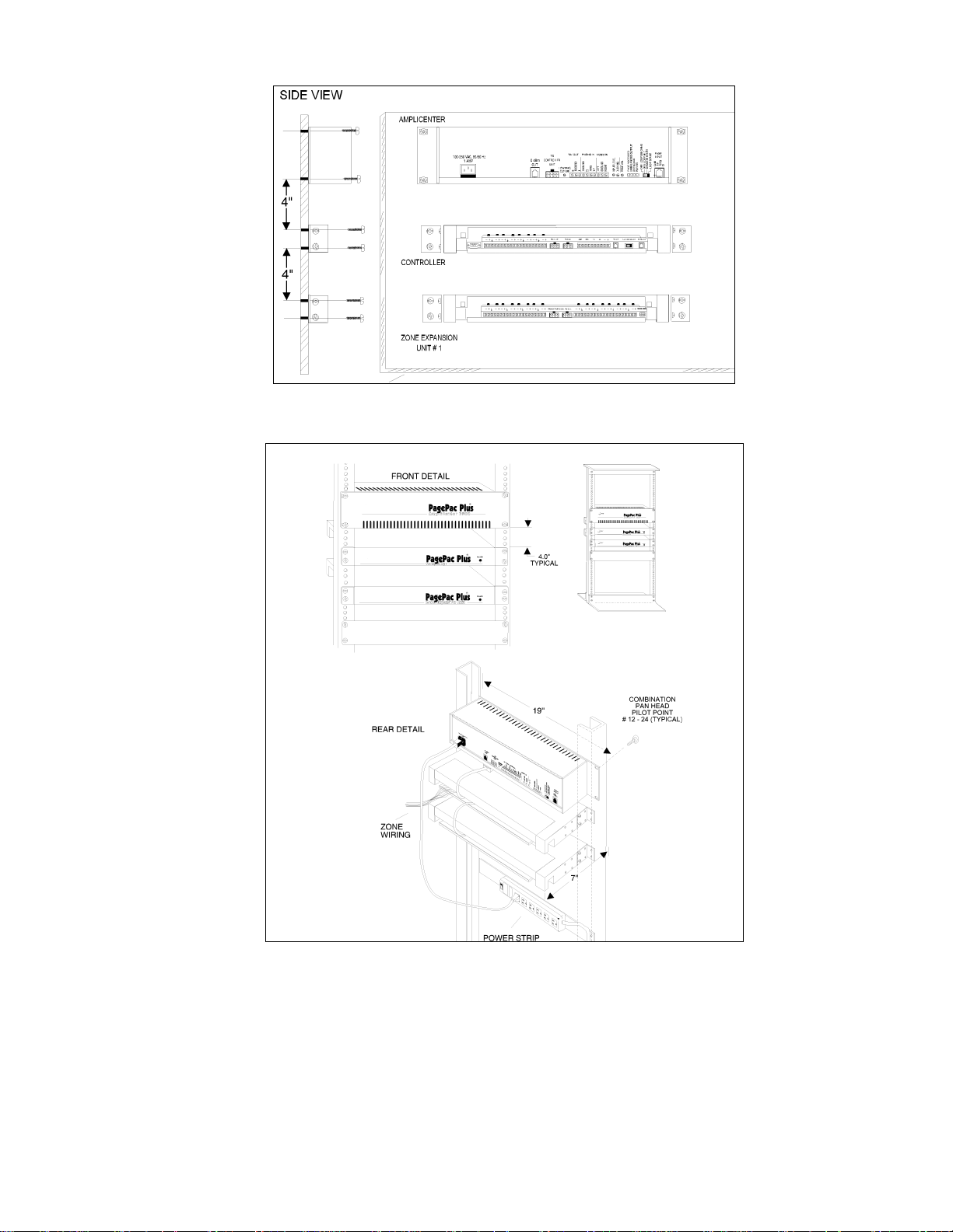
Figure 1. Wall Mounted Hardware
Figure 2. Rack Mounted Hardware
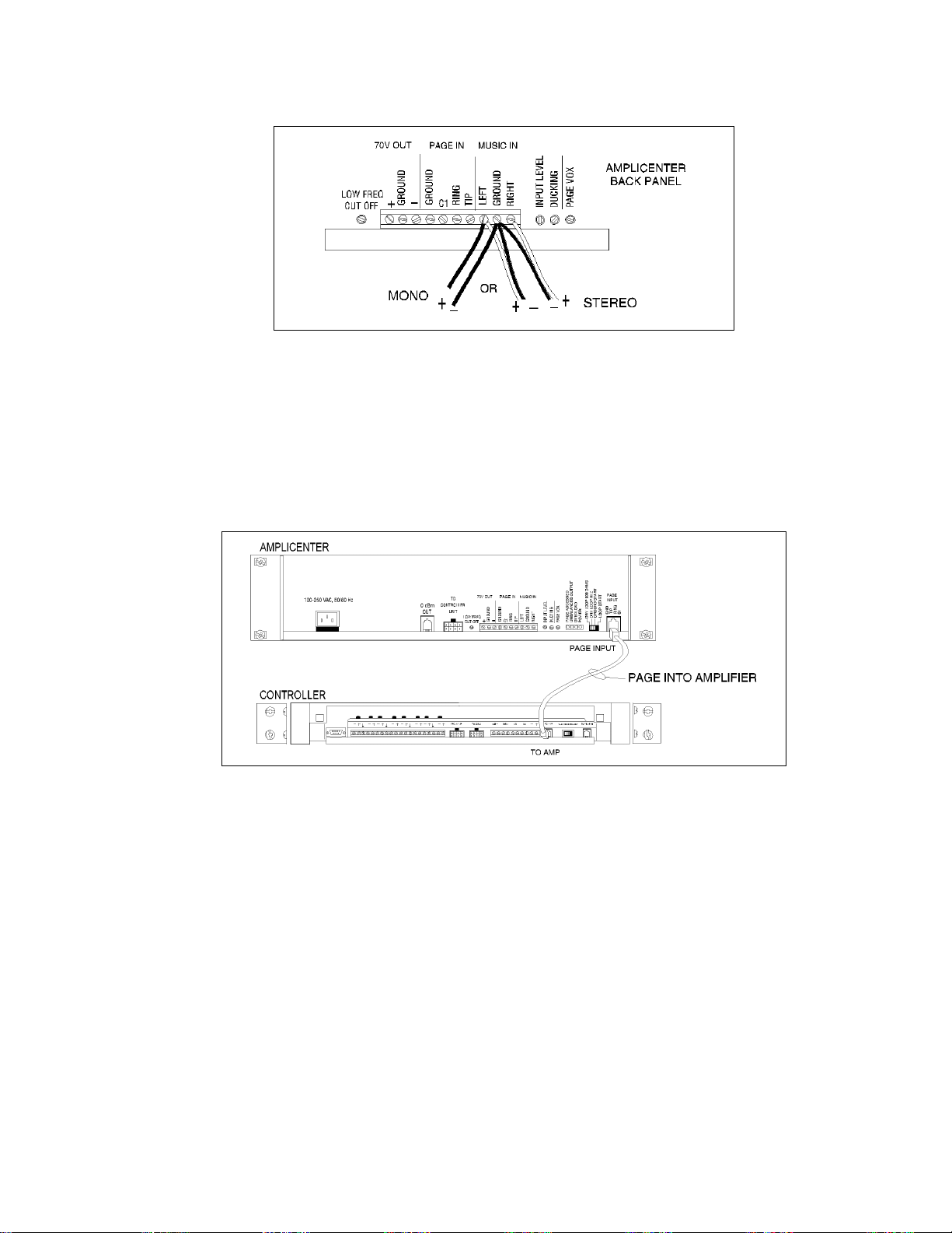
2. Connect background music i nput wires to Left a nd Right termina ls if ster eo, or, Left and Ground if not.
See Figure 3.
Note: The optional audio source can be a CD or tape player, AM, FM, or commercial radio, or other
audio device.
2 947180
Page 3
If more than one AmpliCenter is used in the paging sys tem, each one can be connected to the same
music source, or different audio device, if desired.
Figure 3. Music Input Connections on AmpliCenter
3. Plug modular cord into connectors “To Amp” on Control ler and “Page In” on AmpliCenter
(see Figure 4).
Note: If an amplifier other than the AmpliCenter is used, refer to page 10. There you will fi nd wiring diagrams and notes.
Figure 4. Page In Connection from Controller to AmpliCenter
4. Connect 8-pin Molex connector from AmpliCenter to Controller (see Figure 5).
Note: Connectors can only go in one way. DO NOT force in.
If you are using another type of amplifier, refer to the example system setups.
3 947180
Page 4
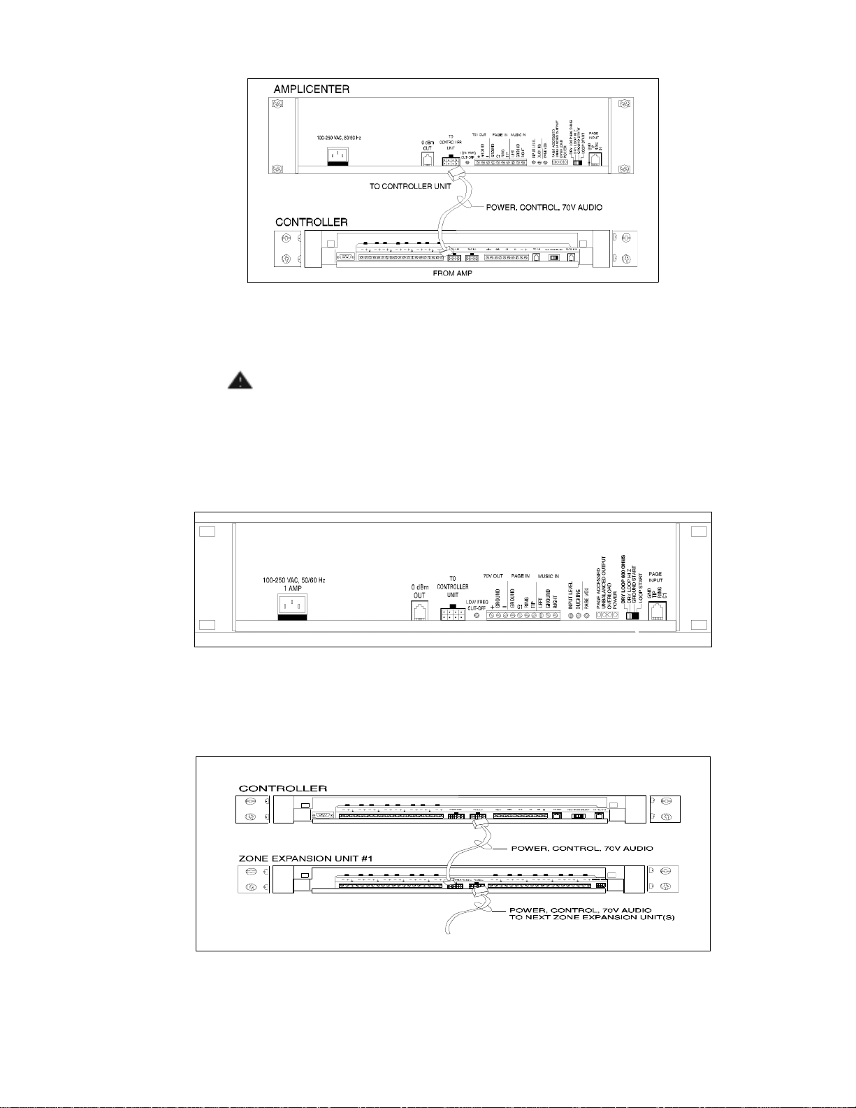
Figure 5. 8-pin Molex Connector from AmpliCenter to Controller
CAUTION:
Damage to Controller will occur if the Molex connector (from AmpliCenter) is
plugged into the right connector (This goes to Zone Expansion Units)
1. Set the AmpliCenter Telephone Mode Selection Switch to Dry Loop 600 Ohms (Far left setting).
See Figure 6.
Figure 6. AmpliCenter Mo de S w itch Setting
2. Connect 8-pin Molex from Controller to Zone Expansion Unit( s), if used. See Figure 7.
.
Note: Up to 3 Zone Expansion Units can be used, providing up to 56 paging and/or control zones.
Figure 7. 8-pin Molex Connector from Control ler to Zone Expansion Unit(s)
4 947180
Page 5
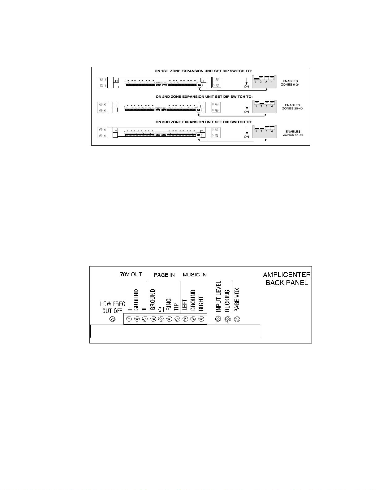
3. Set DIP switches on each Zone Expansion Unit, if any. See Figure 8.
Note: These DIP switches must be set correctly in order for the Controller to recognize the additional
zones.
Figure 8. Setting Zone Expansion Unit DIP Switches
4. Using a small standard screwdriver, make the following adjustments:
a. Adjust the Low Frequency Cut Off control to center position. This control cuts out the low fre-
quency bass so that horns and small speakers are not over-driven and distorted by excessive
bass energy . Cut -off f requency is conti nuously adjust able from 50Hz ( full CCW rotati on) to 400 Hz
(full CW rotation). See Figure 9.
b. Adjust the Page VOX (voice activated) sensitivity to the fully counterclockwise position.
c. Adjust Music Input level to the center position. Clockwise rotation will increase the level. Listen
and set to a comfortable level.
d. Adjust Music Ducking level to the fully counterclockwise position. This feature allows music to
continue to be heard during a page, but at a reduced level . The range is less than –40 dB (full
CCW) to –6 dB (full CW). If music is not connected, set to full CCW.
Figure 9. Sound Level Adjustments on AmpliCenter
5 947180
Page 6
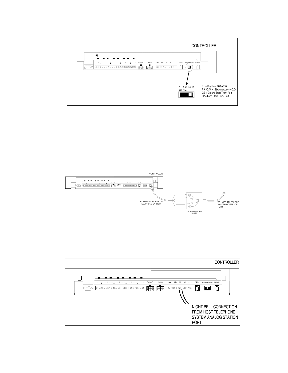
5. Set Telephone Mode switch on Controller to match host telephone system interface port type.
See Figure 10.
Figure 10. Setting Controller Telephone Mode Switch
6. Connect cable from host telephone system to Controller Page Input.
See Figure 11.
Note: Depending on the type of host telephone system interfac e port, the connection may differ slightly
from the illustration to the right. A direct 4-conductor cord from the Controller to the telephone system
can also be used, bypassing the connecto r block.
CONNECT GREEN WIRE TO SYSTEM TIP T
CONNECT RED WIRE TO SYSTEM RING R
CONNECT BLACK W IRE TO THE PAIRED DRY CONTAC T CONTROL LEAD GROUND
CONNECT YELLOW WIRE TO THE PAIRED DRY CONTACT CONTROL LEAD C1
BLACK
GREEN
RED
YELLOW
Figure 1 1. Connecting Host Telephone Sy stem to Controller
7. Connect two wires from the night bell analog st ation port on the host telephone system to Controller
night bell (N.B.) input. See Figure 12.
Figure 12. Night Bell Connection to Controller
6 947180
Page 7
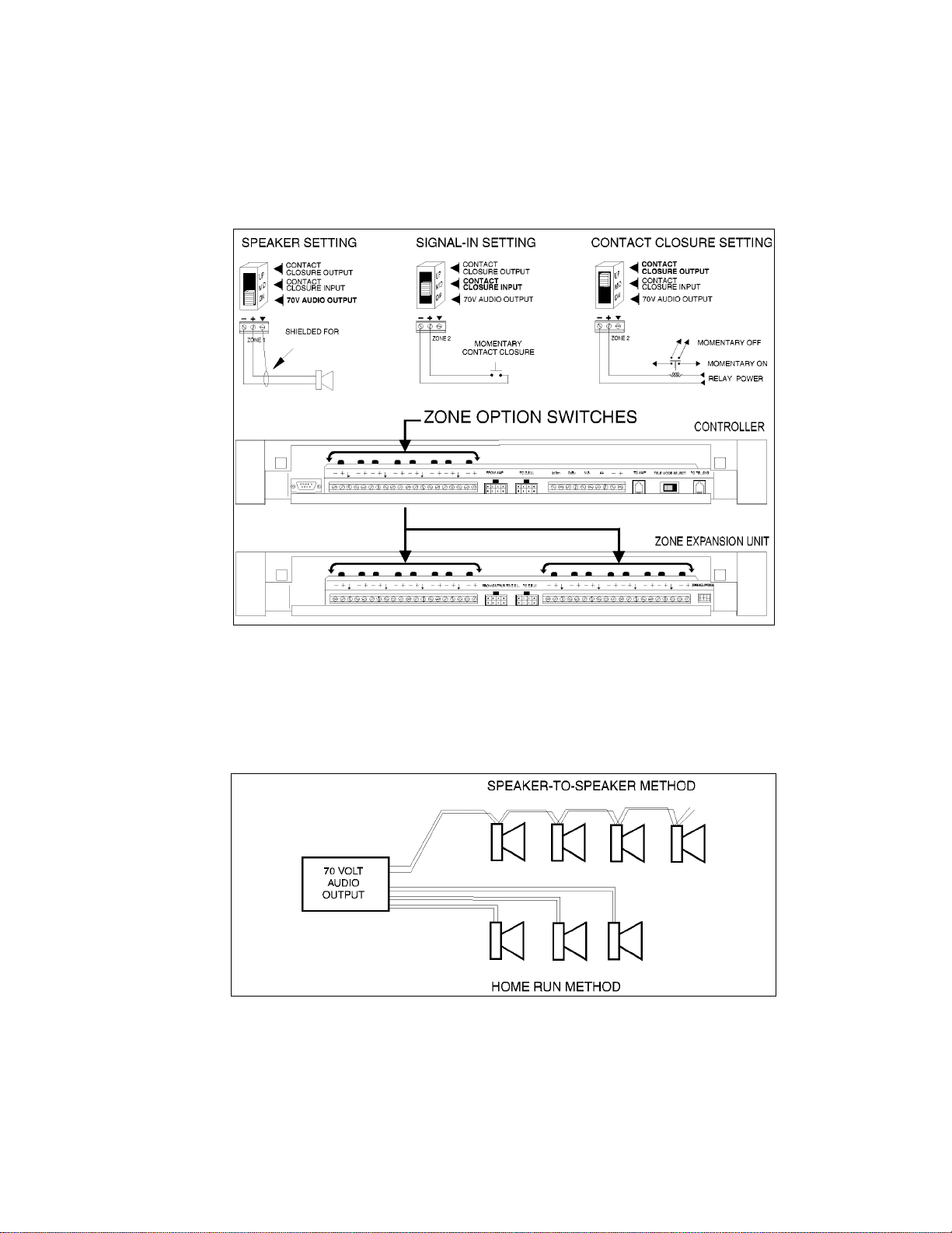
8. Set the Zone Option switches on the Controller and Zone Expansion Units, if any.
Note: For each zone used, no matter what its function, this switch needs to be set to one of three settings for proper zone operation.
The Controller has eight switc hes for zones 1-8. Each subsequ ent Zone Expansion Uni t has switches for
zones 9-24, 25-40, and 41-56.
70V
Figure 13. Setting Zone Option Switches on Controller and Zone Expansion Units
CONNECTING SPEAKERS
Connect each speaker to the appropriate Home Run or Speake r-to-speake r wiring scheme as shown on
the floor plan. See Figure 14.
Figure 14. Speaker Wiring Methods
7 947180
Page 8
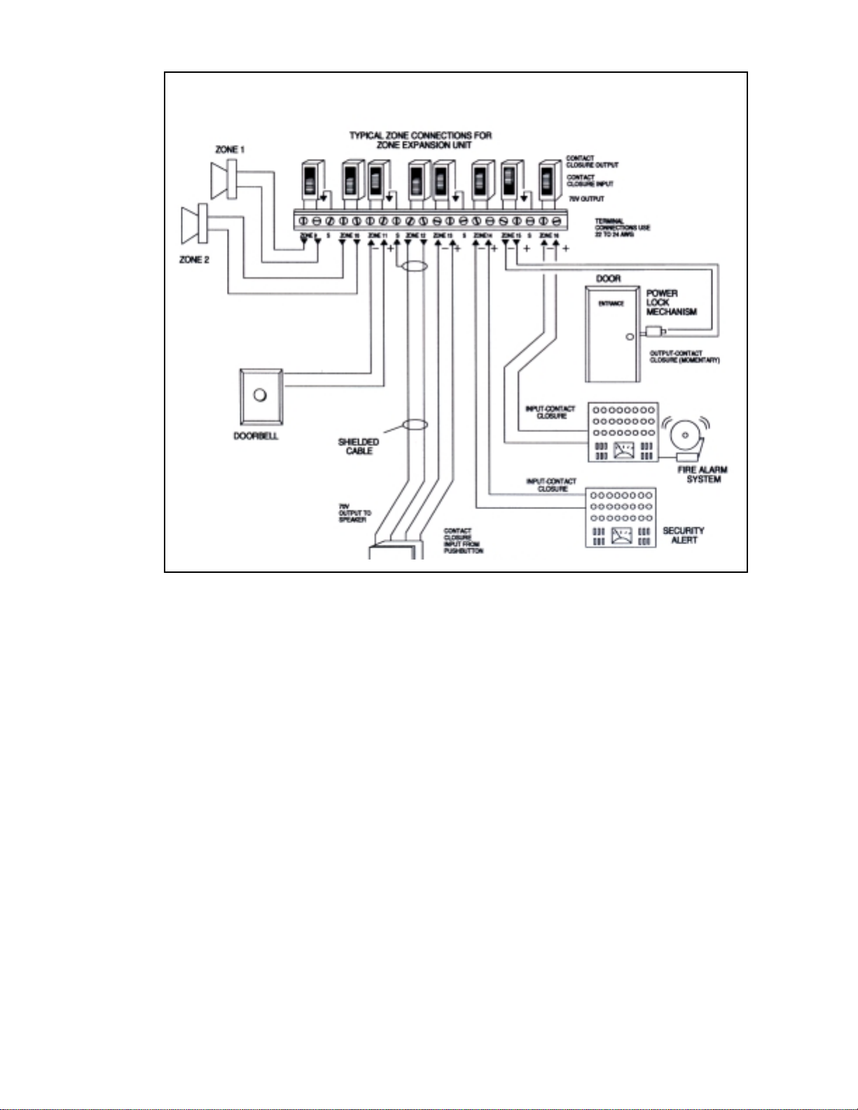
INPUT
CONTACT
CLOSURE
Figure 15. Contact Closure Zone Wiring to Controller
3. Test speaker wiring for short circuits.
Measure the resistance of each home run wiring with an ohmmeter. Any pair indicating a value of less
than 15 Ohms must be rechecked for possible shorted wiring or speakers. Correct any problems and
retest.
4. Make zone connections to Controller and any Zone Expansion Units. See Figure 15.
The zone connectors on the Controller and Zone Expans ion Unit s can accommod ate up to two 22 AWG
wires or four 24 AWG wires per zone output.
Note: DO NOT over tighten zone connector screws.
Check zone option switch setting with Zone Map and Zone Configuration Tables as you connect each
zone (A 70V audio output setting going to other than speakers may damage other equipment).
8 947180
Page 9

POWERING UP SYSTEM
With all zones wired and connected to the Controller and Zone Expansion Units (if any), initial testing
can begin. Refer to Controls and Indicators, Terminals and Connect or
can begin to program the Controller with the featur es for each zone.
1. Plug the power cord into the AC input connector on the AmpliCenter. The following should happen:
a. The green Power LED on the AmpliCenter will turn on and stay on.
b. The green Page Access LED on the AmpliCenter also turns on, but will go out after a few
seconds.
c. On the Controller, veri fy that the green Phone System Enabled LED if off, and that the yellow
Attendant Access Enabled LED is off.
e. If background music is connected, adjust the Music In Input Level control on the AmpliCenter(s)
for an acceptable level.
NOTE: If an amplifier other than the AmpliCenter is used, make sure it i s powe red up and verify the
Controller LEDs.
2. Make an All Zone test page. Readjust sound levels by adjusting speaker tap settings, if required.
a. Readjust Music Input level to the desired loudness relative to paging loudness.
b. Some loudspeaker taps may have to be re-adjusted to get even coverage at all locations. Be sure
that the final speaker tap setting totals do not exceed the power rating of the AmpliCenter.
. Once initial testing is done, you
3. Begin programming the Controller (refer to Programming Section).
SELF-POWERED CONTROLLER CONNECTIONS
The wiring diagrams in Figures 16 through 18 illustrate the connection of the Self-Powered Controller
with other amplifiers. In this way, most features associated with the Controller ca n be util ized with amplifiers other than the AmpliCenter. Refer to Tables 1 and 2 for gain and sensitivity settings.
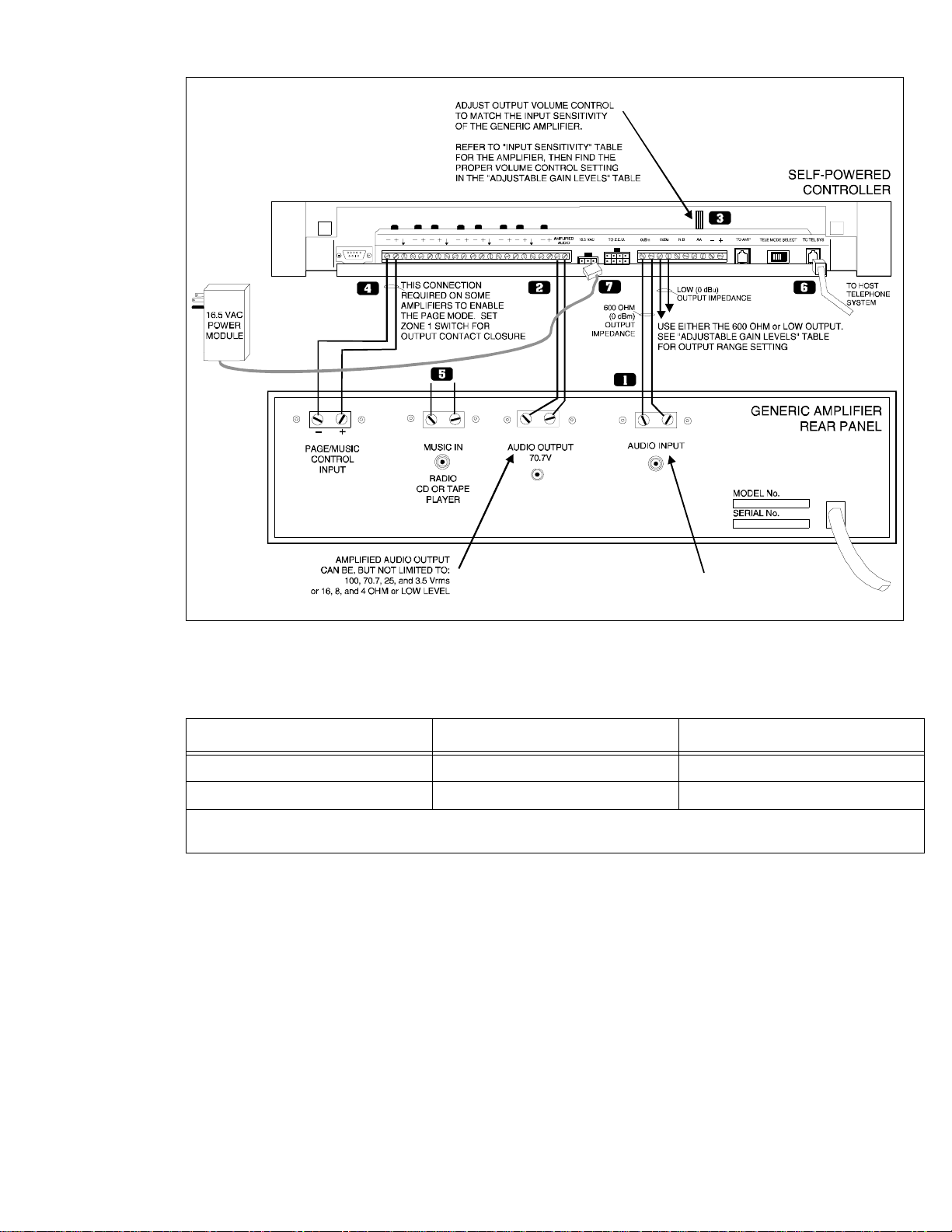
CONTROLLER TO GENERIC AMPLIFIER
To install the Controller to a Generic Amplifier (see Figure 16):
1. Connect 0dBu or 0dBm output to amplifier audio input.
Note: Refer to Tables 1 and 2 for proper audio input requirements and volu me control settings.
2. Connect Amplifier Audio Output (70.7V) to Amplified Audio Input on Controller.
3. Adjust Controller volume control (see Table 1).
4. If required, connect control input to amplifier from Controller zone set to “output contact closure.”
5. Connect background music input, if any.
6. Connect host telephone system to Controller.
7. Plug power pack connector into Contr oller.
9 947180
Page 10
TELEPHONE INPUT OR
AUX INPUT
(DRY INPUT, NO BATTERY OR
VOLTAGE CAN BE PRESENT)
Figure 16. Connection of the Self-Powered Controller to Generic Amplifiers
Table 1. Controller Adjustable Output Levels
Controller Volume Control Setting 600 Ohm Impedance Output Low Impedance Output
Full Counter Clockwise -12 dBm (195mV rms) -6 dBu (388mV rms)
Full Clockwise 0 dBm (.775V rms) +6 dBu (1.5V rms)
*NOTE: The generic amplifiers input must be dry, no battery or voltage can be present Condition: -12 dBm on the telephone
interface or -12 dBu on the attendant access input, both outputs are terminated with 600 ohms.
10 947180
Page 11
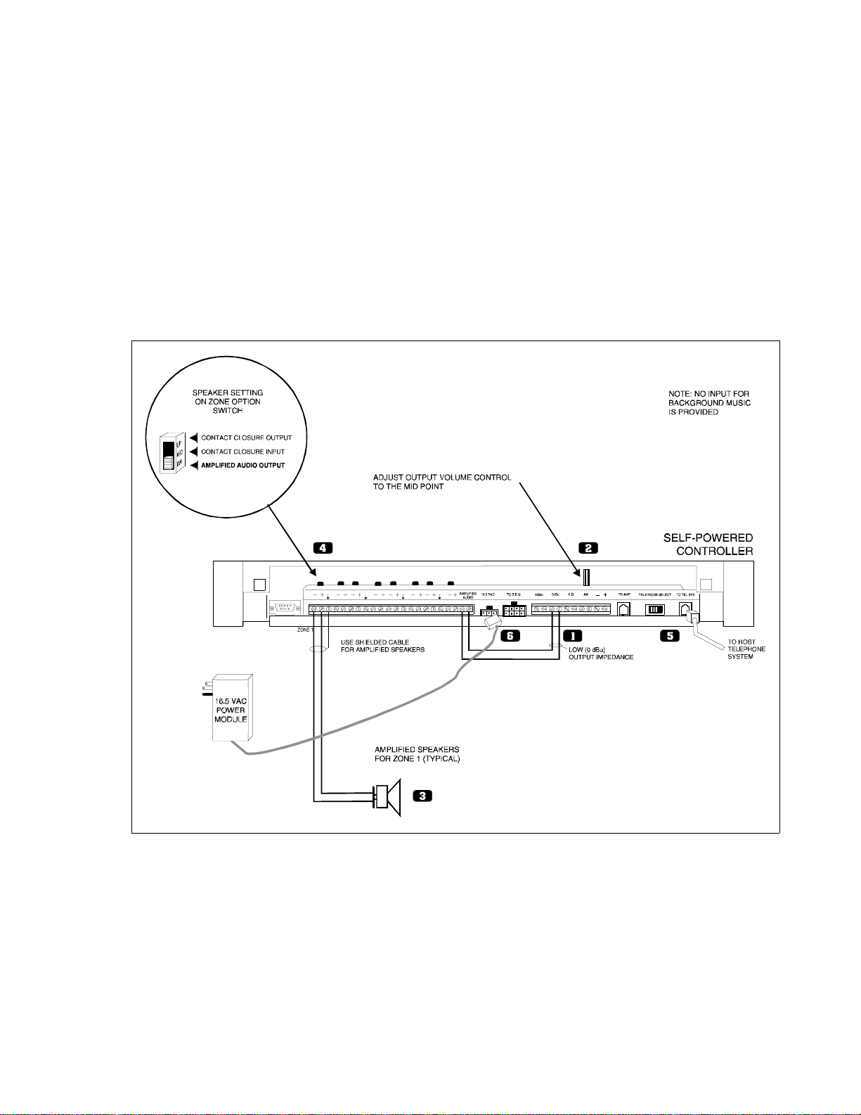
CONTROLLER TO AMPLIFIED SPEAKERS
To install a Controller to Amplifi ed Sp eakers (see Figure 17):
1. Connect 0dBu output from Controller to Amplified Audio input of Controller.
2. Adjust Controller volume control to mid point.
3. Connect amplified speakers to each zone connector.
4. Set zone option switches to Amplified Audio Output.
5. Connect host telephone system to Controller.
6. Plug Power Pack connector into Controller.
Figure 17. Self-Powered Controller Driv ing Amplified Speakers
11 947180
Page 12
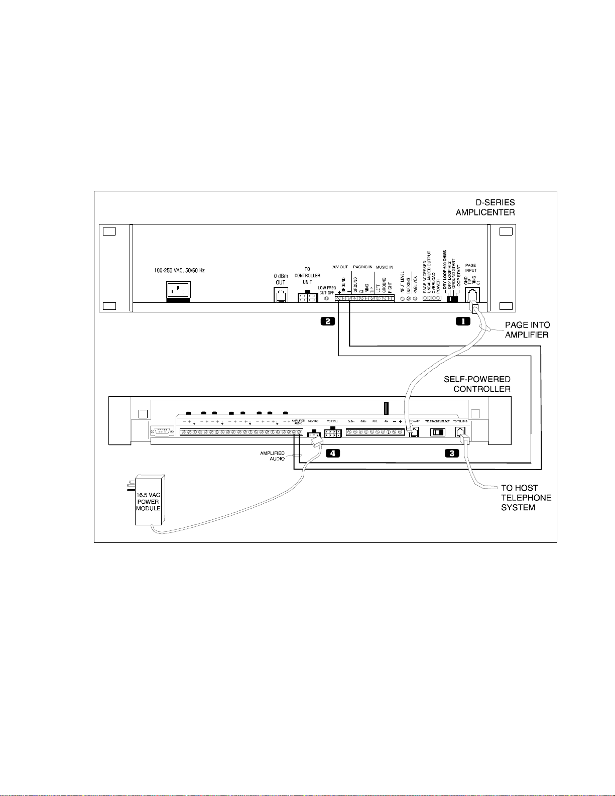
CONTROLLER TO D-SERIES AMPLICENTER
To install a C ontroller to a D-Series AmpliCenter (see Figure 18):
1. Connect 6-conductor cord from Controlle r (To Amp) to AmpliCenter Page Input.
2. Connect 70V audio out from AmpliCenter to Controller Amplifi ed Audio terminals.
3. Connect host telephone system input to Controller.
4. Plug power pack connector into Contr oller.
Figure 18. Self-Powered Controller Connected t o the PagePac D-Series AmpliCenter
12 947180
Page 13

PROGRAMMING THE CONTROLLER
The Controller is programmed to enable each zone to have dif ferent zone featu res, if required. There are
two ways to do the programming. One is via the RS-232 serial port on the Contro ller which is connec ted
to an IBM compatible (DOS) PC using the optional programming software.
An advantage of using a PC to configure the Controller is that screens can be viewed on the monitor to
aid in selecting the zones for various option s. A re-programming of the entire sys tem can be done before
downloading the configurat ion to the co ntroller, saving down time. Furthermore , the old conf iguration ca n
be saved and used again.
The other method works via the telephone access port (like calling to make a page), which accepts only
touchtone telephone keypad inputs (DTMF) tones. The Controller has the ability to retain all programming options in non-volatile EEPROM memory or as a .CFG (configuration) file on a personal computer.
PROGRAMMING STEPS
CAUTION:
The Zone Option switches must be set before the system is powered up, and
therefore before programming commences
The Zone Option switches on the rear of the Controller and Zone Expansion units must be set to match
the zone option selected for programming. The slide switch for each zone must be manually set to Contact Closure (to swit ch on/of f a device, such as a door securi ty lock, r emote ampli fier, etc.), Input Contact
Closure, or Audio Output, depending on the mode selected for each zone.
.
IMPORTANT! It is recommended that the paging zone decisions be made and filled in on the Zone Map
and Configuration Tables, located on p ages 32-35 prior to setting zone option switches and
programming.
ENTER PROGRAMMING MODE
* *
1. From any DTMF telephone in the system, dial the paging access extension.
2. Dial the Connect Password (if optioned).
You will hear the paging system dial tone.
3. Dial
You will hear confirmation tone, then dial tone. Now programming may begin.
* *
1 0 RESET TO FACTORY DEFAULTS
1. Dial 1 0
You will hear two beeps from the Controller.
2. Dial 2 5 3 2 7
After a long pause, you will hear 3 beeps from the Controller. The controller is now set to factory default
conditions.
3. Program the system options (refer to the following paragraphs).
You may exit the programming mode by dialing #.
13 947180
Page 14

2 0 DEFINE LENGTH OF ALIAS NUMBERS
This system option allows you to set the length (3 or 4 digits) of the ALIAS number field. The default is 2
digits. If you wish to ass ign ALIAS numbers to the pagi ng zones, you mu st set the le ngth p arameter. The
ALIAS number is the dialing extension for the zone. If no ALIAS numbers are used, the Physical Zone
Code is the dialing extension for a zone.
First access the PagePac Plus system and enter the programming mode by pressing
entering your Programming password (if optioned). You may exit the programming mode by dialing #.
Note: This MUST be done before “Zone Map Option – Assigning ALIAS Numbers,” later in this section.
1. Dial 2 0 to select this option.
Hear a DOUBLE beep.
Press 3 or 4 to set length of ALIAS numbers (number of digits dialed to reach paging zone).
Hear TRIPLE beeps.
3. To verify the setting, dial 2 1 and repeat step 2 above.
∗ ∗ and then
2 2 SET SERIAL PORT BIT RATE
The speed (bit rate) of the controller 's RS-232 serial port can be set to the rate of the computer monitor
or visual display. Default is 9600 bps. The bit rate may be changed at any time, but the Controller must
be reset (power off then on again) in order to take effect.
1. Dial 2 2 to select this option
Hear a DOUBLE beep.
2. Dial a code to select the Serial Port Bit Rate
0 to select 300 bps
1 to select 1200 bps
2 to select 2400 bps
3 to select 4800 bps
4 to select 9600 bps
5 to select 14400 bps
6 to select 19200 bps
Hear TRIPLE beeps.
3. To verify the status of this option, dial 2 3 and repeat step 2 above.
2 4 INHIBIT DIAL TONE DETECT
Supervision of the Station/Centrex Access mode is accomplished in 3 ways, by monitoring the loop current and the audio signal (including dial tone), and a forced disconn ect timer . Thi s option (only applicab le
in the station access mode) enabl es you to defeat the dia l tone detect funct ion in order to send a tone vi a
the Telephone Interface to the output.
1. Dial 2 4 to select this option.
Hear a DOUBLE beep.
2. Dial 0 to turn Enable, or 1 to turn Inhibit.
14 947180
Page 15

Hear TRIPLE beeps.
3. To verify the condition (OFF/ON) of the Dial Tone Detect option, dial 2 5 and repeat step 2 above.
3 0 SET CONNECT PASSWORD
This feature will not become active until the first time you enter a pa ssword, via the programming mode.
The factory default is NO p as sword. The Connect p asswor d operate s as a sec urity bl ock int o t he p agi ng
system, restricting paging access to authorized users.
Note: You may want to use a short Connect password (2 or 3 digits only) for ease of use.
1. Dial 3 0 to select this option.
Hear a DOUBLE beep.
2. Enter the Password you wish to use (up to 6 dig it s) . If the p ass word ha s fe wer t han 6 digi t s, ent er the
# to terminate the string.
Note: For example, 123456 is a valid password entry. 123# is also a valid password entry, resulting in
the password 123.
If you already have entered a password and want to remove it (to have NO password), just enter the #
alone. Hear TRIPLE beeps.
To verify that the new Connect password has been established, dial 3 1 and repeat step 2 above.
3 2 SET PROGRAMMING PASSWORD
Establishing a Programming password will restrict access to the programming mode of the PagePac
Plus paging system. It is recommended that access to programming be restricted to the System Administrator, Telecommunications Manager, or oth er selected users.
Note: Your Connect and Programming passwords should not be the same. If this feature is active and
the system has been accessed via the telephone interface, then after the first digit of your Programming
password is pressed, t he dial tone wil l stop and wi ll not be retur ned until the co rr ect passwor d i s enter ed
or until the user hangs up and re-enters the system.
This feature will become active once any programming passwor d has been entered via t he programming
mode. You are not required to establish such a password. The fac tor y-set default programming pass-
word is
1. Dial 3 2 to select this option.
Hear a DOUBLE beep.
2. Enter the Password you wish to use (up to 6 dig it s) . If the p ass word ha s fe wer t han 6 digi t s, ent er the
∗ ∗.
# to terminate the string.
If you already have entered a pas sword and now want to remove it ( to have NO password), just enter the
# alone.
For example, 234567 is a valid password entry. 234# is also a valid password entry, resulting in the
password 234.
15 947180
Page 16

Hear TRIPLE beeps.
3. To verify that the new Programming password has been established, dial 3 3 and repeat step 2
above.
Forgot the Password? If either or both the connect password and programming password are forgotten, it will be necessary to call the Help line (refer to page ii) for instructions how to erase the two passwords and be able to enter new ones.
4 0 TURN CONFIRMATION TONE ON/OFF
When the option is ON, a tone will be sent to the telephone interf ace after a zone has been selec ted and
before a page can be made. The default setting is ON.
1. Dial 4 0 to select this option.
Hear a DOUBLE beep.
2. Dial 0 to turn OFF, or 1 to turn ON.
Hear TRIPLE beeps.
3. To verify the Confirmation Tone condition (OFF or ON), dial 4 1 and repeat step 2 above.
4 2 TURN PRE-ANNOUNCEMENT TONE ON/OFF
This tone is very similar to the initial talk-back warning tone, in the sense that it is sent to a zone when
the zone is accessed. This tone wi ll be sent ou t to both the zone select ed and to th e telephone int erface.
After this tone is sent, you may begin your page message. Default is ON.
1. Dial 4 2 to select this option.
Hear a DOUBLE beep.
2. Dial 0 to turn OFF, or 1 to turn ON.
Hear TRIPLE beeps.
3. To verify the condition (OFF or ON) of the pre-announcement tone, dial 4 3 and repeat step 2 above .
4 4 SET TALKBACK WARNING TONE
This tone is intende d to alert a person that their conversation is being monitored through the paging system loudspeaker. If Talkback is optioned for YES, then the choices will be Initial, 30 Second Repetition,
or Off. The default setting for this parameter is Initial and 30 Second Repetition.
1. Dial 4 4 to select this option.
Hear a DOUBLE beep.
2. Dial 0 to turn OFF, 1 to select INITIAL tone only, or 2 to select Initial and 30 Second repeat.
Hear TRIPLE beeps.
3. To verify the condition of the Talkback Warning tone, dial 4 5 and repeat step 2 above.
16 947180
Page 17

5 0 SET VOX DISCONNECT TIMING
The system will hang up on a page if no audio is detected for the programmed amount of time. The
default time is 30 seconds, but can be varied from 10 seconds to 60 seconds, in 10 second increments,
or can be disabled completely.
1. Dial 5 0 to select this option.
Hear a DOUBLE beep.
2. Dial the code to select a duration for the VOX Disconnect Timing:
0 to turn OFF
1 to select 10 seconds4 to select 40 seconds
2 to select 20 seconds5 to select 50 seconds
3 to select 30 seconds6 to select 60 seconds
Hear TRIPLE beeps.
3. To verify the duration of the VOX Disconnect Timing, dial 5 1 and repeat step 2 above.
5 2 ENABLE COMPUTER MONITOR
This option selects a device to be connected to the Controller RS-232 port, a computer monitor for logging of all paging activity or a visual message display. The default setti ng is Computer Monitor.
By selecting Computer Monitor (the default opti on), the system is enabled to monitor activity on Attendant Access, Telephone Interface, and Night Bell inputs. This feature requires that a PC computer be
connected to the RS-232 port of the Controller. Whenever the input becomes active, ASCII characters
will be sent out the RS-232 port (DB9 pin connector) to the computer. The ASCII characters will be intercepted by a special software package in the comput er that logs the time, date, input zone, type of activity , zone that was p aged, and durati on of the activity. All such input activity to th e paging system can then
be viewed (and recorded) on the computer.
By selecting Display, the monitoring activity described above enables commands to be sent to a visual
message display where preprogrammed messages are displayed.
1. Dial 5 2 to select this option.
Hear a DOUBLE beep.
2. Dial the 0 to select Computer Monitor, or 1 to select Visual Display
Hear TRIPLE beeps.
3. To verify the status of this option, dial 5 3 and repeat step 2 above.
If a Computer Monitor or visual message display has been connected and Controller software loaded,
you will need to select the types of paging inputs to be displayed or recorded. See next programming
option “Input Computer Monitor.”
17 947180
Page 18

5 4 SELECT INPUT TO COMPUTER MONITOR
This option turns ON or OFF the inputs of Attendant Access, Telephone Access, and Night Bell to be
recorded and displayed by the Computer Monitor i f you have activated it in S tep 10. Default is OFF for all
three.
You will repeat this procedure 3 times in order to reset all three inputs.
1. Dial 5 4 to select this option.
Hear a DOUBLE beep.
2. Dial the code to select an option for one of the three in puts:
0 to turn OFF the Attendant Access.
1 to turn ON the Attendant Access.
2 to turn OFF the Telephone Access.
3 to turn ON the Telephone Access.
4 to turn OFF the Night Bell.
5 to turn ON the Night Bell.
Hear TRIPLE beeps.
3. To verify the status of this option, dial 5 5 and repeat step 2 above.
5 6 SET SUPERVISED TRUNK MODE
If the host telephone system does not have a supervised tr unk option this feature does not apply.
Proceed to Step 14.
Note: Once the option has been configured, you should place the Controller Telephone Mode switch to
the Ground Start position. Connect the telephone interface to a Loop S tart trunk on the host system
using a standard two-conductor (not four-conductor) RJ-11 cable.
The Supervised Trunk access mode provides both VOX Disconnect and Forced Disconnect timeouts.
When the Controller detects that the it has been off hook for two minutes, it opens the trunk circuit for
one second, ending the call. Also, if no voice activity is detected fo r the period specified by the VOX Disconnect programming option (normal ly 30 second s), or if the tel ephone is ov err idden by a hi gher pri orit y
activity (i.e., attendant access), the call is disconnected.
Note: The Ground Start and Station Access modes are not available when the Control ler is configured
for Supervised Trunk mode. Supervised Trunk mode must be turned off to re-enable these access
modes.
1. Dial 5 6 to select this option
Hear a DOUBLE beep.
2. Press 0 to turn OFF, or 1 to turn ON
Hear TRIPLE beeps.
3. To verify the condition (ON/OFF) of the Supervised Trunk mode, dial 5 7 and repeat step 2 above.
18 947180
Page 19

5 8 SPECIFY ZONE MICROPHONE
This option allows you to specify that a zone microphone is attached to the Attendant Access interface.
When the Zone Microphone option i s enabled ( ON), th e controller will wai t for a zone to be selected from
the microphone keypad before it makes a page. When disabled (OFF), the controll er revert s to it s normal
(All Call) operation.
1. Dial 5 8 to select this option
Hear a DOUBLE beep.
2. Dial 0 to turn OFF, or 1 to turn ON
Hear TRIPLE beeps.
3. To verify the condition (OFF/ON) of the Zone Microphone option, dial 5 9 and repeat step 2 above.
GENERAL ZONE AND ZONE GROUP CONFIGURATIONS
General Zone and Zone Group Configurations are opti ons that apply to sel ected zone s or gr oup s, not to
the entire system. The steps following Copy Command, describe each option.
1 2 COPY COMMAND
The COPY command can be used to copy the conf iguration of a zone that has al ready been opt ioned, t o
one or more additional zones. This saves re-entering the same parameters over again, to duplicate the
parameters of an existing zone.
1. Dial 1 2 to activate COPY command.
Hear a DOUBLE beep tone.
2. Enter the zone number that you wish to copy from (i.e., 01).
Hear DOUBLE beep tone.
3. Enter the zone number of the beginning of the range of zones you wish to copy to.
Hear a DOUBLE beep tone.
4. Enter the zone number of the END of the zone range to be copied to.
Hear a TRIPLE beep tone.
Note: Program the Controller using the physical zone number.
For example, to copy the parameters of zone 01 to all other zones, the range zone 02 to 56 would be
entered in this step and the next. To copy to a single zone (for example, 02) enter that zone number as
both the beginning and the end of the range (02 to 02). In this step, enter only the beginning zone of the
zone range.
6 0 ZONE MAP OPTION -- ASSIGNING ALIAS NUMBERS
Note: Before doing this option, you MUST do “Define Length of ALIAS Numbers” (see Step 3).
Zone Map permits you to assign the dialing code, called the ALIAS zone code, that you will dial to
access a particular zone by telephone (i.e., instead of dialing 02 to make a page, you could di al 2202).
The factory default is NONE: no ALIAS numbers are pre-programmed. The zones are identified by their
2-digit Physical Zone Codes (01 thru 56 and groups 81-88) as the default condition.
19 947180
Page 20

Digit string length for an ALIAS code c an be 3 or 4 digits, but all ALIAS codes must have the same number of digits. (Refer to Step 3) The
Note: If ALIAS numbers are enabled, you MUST use them for programming from now on. When an
ALIAS number for a zone is changed, all the previous zone opt ions for that zone will be transfer red to the
new zone number .
Refer to your own Zone Map and the Example Zone Map at the end of this programming section.
1. Dial 6 0 to select this option.
Hear a DOUBLE beep.
2. Enter the 2-digit PHYSICAL zone/group code, of the zone to be given an ALIAS number.
Hear a DOUBLE beep.
3. Enter the ALIAS zone/group number you have chosen.
Hear TRIPLE beeps.
4. To verify the assignment of an ALIAS to a selected zone or group, dial 6 1 and repeat steps 2 and 3
above.
∗ and # digits are not applicable digits for zone ALIAS numbers.
6 2 TYPE OF ZONE: INPUT OR OUTPUT
The choices here are INPUT #1, INPUT #2, and OUTPUT. Be sure the manually select able Zone Opti on
switch on the rear of the Controller or Zone Expansion Unit is set to match the type of zone selected
(input or output). Input #1 would be used for an emer gency alert, say a connecti on to your al arm system.
Input #2 would be a lower priority, say a doorbell input.
Note: The INPUT #1 option must only be assigned to physical zones 1 through 8 (on the Controller).
The factory default is OUTPUT (i.e., all zones are output type, by default).
1. Dial 6 2 to select this option.
Hear a DOUBLE beep.
2. Enter the number of the zone or zone group to be optioned. Use ALIAS numbers, if optioned.
Otherwise, use Physical zone/group numbers.
Hear a DOUBLE beep.
3. Press 0 to designate the zone as OUTPUT
Press 1 to designate it as INPUT #1, or
Press 2 to designate it as INPUT #2.
Hear TRIPLE beeps.
4. To verify the zone type assignment, dial 6 3 and repeat step s 2 and 3 above.
20 947180
Page 21

SET INPUT PRIORITY ARRANGEMENT
The input priorities are pre-set at the factory. You may only assign a priority level to inputs such as doorbell or security alarm, by assigning them to Input #1 or Input #2, which differ in priority.
Note: These priorities cannot be rearranged. Also, if you select more than one zone to be inputs of the
same level (Input 1, fo r example) , such input s will be handled on a first i n, fir st serve d basis. See Type of
Zone option, under Zone/Group Configurations programming, later in this section.
The default setting is:
1 – Attendant Access
2 – Input #1
3 – Telephone Access
4 – Input #2
5 – Night Bell
Music (always lowest priority).
6 4 SET ZONE GROUPING TO PAGE
This option allows you to select a group of zones to be paged at the same time. The number of zone
groups that can be formulated is eight ; the maximum number of zones per group is 56 zones.
The factory default is NONE (there are no default zone group s).
You will need to repeat this procedure for each zone group you wish to set up.
1. Dial 6 4 to select this option.
Hear a DOUBLE beep.
2. Enter the zone code, of the zone group to be defined (81 thru 88).
Hear a DOUBLE beep.
For example, dial 81 for zone group 81 (Zone group 80 is always All Call). Use ALIAS numbers, if
optioned. Otherwise, use Physical zone/group numbers.
For example, 01 (tone), 02 (tone), 13 (t one), 14 (tone), #, indicates zones 1, 2, 13, and 14 are included in
this group. Enter the codes consecutivel y, with no digit or character between them. Us e ALIAS numbers,
if optioned. Otherwise, use Physical zone/group numbers.
3. Enter zone codes of each zone to be included in the group.
Hear a Confirmation Tone for each zone, then dial tone.
4. Press # to end the string of zones.
Hear TRIPLE beeps.
5. To verify the zone group assignment, dial 6 5 and repeat steps 2 and 3 above.
21 947180
Page 22

6 6 SET ZONE OR GROUP ZONE TO REMOTE MONITOR
This option selects a zone or group zone for comput er monitoring, (logging of paging activity), or for
visual message display. The default setting is off (Refer to Step 10).
1. Dial 6 6 to select this option.
Hear a DOUBLE beep.
2. Enter zone or group zone number.
3. Dial the code to activate this option:
0 to select OFF
1 to select ON.
Hear TRIPLE beeps.
4. To verify the status of this option, dial 6 7 and repeat step 2 above.
OUTPUT ZONE/GROUP CONFIGURATIONS
These options apply to zones or groups already configured as outputs (see Step 17, Type of Zone). All
these parameters can be individually optioned per zone. For a summary of these options, see the Programming Quick Reference Chart at the end of this section.
7 0 SET OUTPUT ZONE TYPE
This option selects the t ype of output f or an indiv idual output zone. The c hoices here ar e Audio/Normally
Open, Normally Closed, System Handshake, Moment ary Open, Toggle, Phant om, and Attendant Access
Handshake. The Audio/Normally Open option is the default. The primary use for the Normall y Closed Or
System Handshake is to determine how the switch closure is to funct ion.
When the System Handshake option is chosen, the closure wi ll energize when a valid Off Hook condition
has been detected. The Attendant Access Handshake zone provides an output contact closure when
Attendant Access interface is ready to make a page.
Note: System Handshake is a feature required by certain PBX syste ms: wh en they access the paging
system, they require a return acknowledgment signal – the “handshake” – from the Controller.
A Phantom Zone is an output zone that exist s only in sof tware. If a p age i s made to a Phantom zone, the
controller will send a message to an attached monitoring device (if configured) and will issue confirmation tone, but will t ake no ac ti on with r espec t to th e zone' s hardware. Thi s allo ws uni nst all ed zones t o be
used to select messages on a visual display.
The Momentary Open, Normally Closed and Toggle options are intended to be used for controlling door
striker plates, for inst an ce, to permi t a security door to be unloc ked. The Moment ary Open will st ay ener gized for as long as the zone is selected. The Toggle will stay energized for as long as the zone is
selected. Normally Closed wil l open onl y when the speci fic zone is se lected. Neither of these modes wi ll
respond to an Attendant Access page, an All-Call and/or Zone Group ing page.
Repeat this procedure for each output zone.
1. Dial 7 0 to select this option.
Hear a DOUBLE beep.
22 947180
Page 23

2. Enter the output zone number.
Hear a DOUBLE beep.
Note: Use alias numbers, if optioned. Otherwise, use physical zone/group numbers.
3. Enter the code for the type of output you wish to select:
0 selects AUDIO/N.O. (Normally Open)
1 selects Momentary Open
2 selects N/C (Normally Closed)
3 selects Sys HS (System Handshake)
4 selects To gg l e
5 selects Phantom
6 selects AA Ready (Attendant Access Handshake)
Hear TRIPLE beeps.
4. To verify the Type of Output assignment, dial 7 1 and repeat steps 2 and 3 above.
7 2 SET PAGE ENABLE
This output zone parameter enab les paging for a selected output zone or zone grou p. The choice for this
selection is YES/NO, with the default being YES. Repeat this procedure for each output zone or zone
group.
Note: If you make an all-call page and this option is selected NO in either a zone group or individual
zones, then an all-call page will be made to all other zones except the ones specified. If the decision is
NO for the all-call zone and an all-call page is made, then an error tone will be returned to you.
1. Dial 7 2 to select this option.
Hear a DOUBLE beep.
2. Enter the zone number, of the zone or group you wish to configure.
Hear a DOUBLE beep.
Note: Use ALIAS numbers, if optioned. Otherwise, use physical zone/ group numbers.
3. Enter 0 for NO (Page Not Enabled) or 1 for YES (Page enabled)
Hear TRIPLE beeps.
To verify the status of Page Enable for a given zone, dial 7 3 and repeat steps 2 and 3 above.
7 4 SET MUSIC ENABLE IF BACKGROUND MUSIC IS USED
This is an individual zone output par a meter, that enables background music to be broadcast to a
selected output zone (in the absence of a higher priority p ag ing output) . The choice is YES/NO, with the
default being NO. Repeat this procedure for each out put zone that you wish to have background music.
1. Dial 7 4 to select this option.
Hear a DOUBLE beep.
2. Enter the zone or group zone number.
Hear a DOUBLE beep.
23 947180
Page 24

Note: Use ALIAS numbers, if optioned. Otherwise, use physical zone/ group numbers.
3. Enter 0 for NO (Music Not Enabled) or 1 for YES (Music enabled)
Hear TRIPLE beeps.
4. To verify the status of Music Enable for a given zone, dial 7 5 and repeat steps 2 and 3 above.
7 6 SET TALKBACK ENABLE
This is a zone output parameter that enables t alkback cap ability for a selected output zone or group. The
choice is YES/NO, with the default being set to NO.
All speakers in a zone or group will be active 2-way speakers if talkback has been enabled for a zone.
Repeat this procedure for each output zone or zone group that you wish to have talkback.
1. Dial 7 6 to select this option.
Hear a DOUBLE beep.
2. Enter the zone or group zone number.
Hear a DOUBLE beep.
3. Enter 0 for NO (Not Enabled) or 1 for YES (Enabled)
Hear TRIPLE beeps.
4. To verify the status of Talkback Enable for a given zone, dial and repeat steps 2 and 3 above.
Note: Only 2 talkback speakers are recommended per zone.
7 8 SET NIGHT BELL ENABLE
This is an individual zone output para meter. The choice is YES/NO with the default being NO. With this
parameter set to YES, ni ght bell will be sent to selected outputs whenever ring voltage is present on the
night bell input (from the PBX to the controller).
If a closure is required to trigger the night bel l, then a zone will need to be configured as an input to send
night bell to designated zones when a closure is present. This is discussed in Steps 27 and 28, Tone
Selection and Tone Routing.
You will need to repeat this procedure for each output zone that you wish to receive the night bell signal.
1. Dial 7 8 to select this option.
Hear a DOUBLE beep.
2. Enter the zone or group zone number.
Hear a DOUBLE beep.
Note: Use ALIAS numbers, if optioned. Otherwise, use physical zone/ group numbers.
3. Enter 0 for NO (Not Enabled) or enter 1 for YES (Enabled)
Hear TRIPLE beeps.
4. To verify the status of Night Bell Enable for a given zone, dial 7 9 and repeat steps 2 and 3 above.
24 947180
Page 25

9 0 PASS DTMF TO THE OUTPUT
This zone output option enables the Touchtone telephone keyp ad tones ( DTMF) to be passed through
the Controller and output to a second controller or other auxiliary device.
The choice is YES/NO, with the default being NO. Operating the unit in the default mode, you ma y
switch from zone to zone (within the same Controller) without hanging up, simply by dialing the zone
number of the zone you wish to switch to. The DTMF tones you di al will be muted ( not sent o ut as audio )
as soon as they are detected by the controller.
Access to the first zone will be disconnected when the zone switch has been accomplished
When you have accessed a zone with this parameter set t o YES, DTMF will be sent out as un-muted
audio but the Controller will not respond to the DTMF tones (and will not switch zones).
This YES option, with DTMF tones enabled to the output, is useful when you have more than one Con-
troller connected in a system. The DTMF tone is p assed t hrough the first c ontrol ler (not triggeri ng a zone
change) to the second controller (or other auxiliary device).
You will need to repeat this procedure for each output zone or zone group that you wish to receive the
DTMF tones.
1. Dial 9 0 to select this option.
Hear a DOUBLE beep.
2. Enter the zone or group zone number.
Hear a DOUBLE beep.
3. Enter 0 for NO (Not pass DTMF) or enter 1 for YES (Pass DTMF)
Hear TRIPLE beeps.
4. To verify the status of DTMF Pass for a given zone, dial 9 1 and repeat steps 2 and 3 above.
INPUT ZONE/GROUP OPTIONS
These options apply to zones or groups already configured as input s (see T ype of Zone, S tep 17). These
options are summarized in the Programming Quick Reference Chart, at the end of t his section.
9 2 TONE SELECTION
If a zone is configured to be an input and is activate d, then a tone may be selected to be directed to
whatever zone(s) are selected in Tone Routing, below. The tone selections are listed in step 3.
For example, you wish to have a doorbell pushbutton input cause a chime to be heard in certain zones.
You have already configured the zone of the doorbell as an input zone. You need to select the tone
(chime) you wish to be heard in the output zones, when the doorbell is pressed. This is called Activate
Tone via an Input Closure, on the Quick Reference Chart.
The default setting for this option is NONE (not act ivated).
1. Dial 9 2 to select this mode option.
Hear a DOUBLE beep.
25 947180
Page 26

2. Enter the number of the input zone (i.e., the zone containing the doorbell pushbutton).
Use ALIAS numbers, if optioned. Otherwise, use Physical zone/group numbers.
Hear a DOUBLE beep.
3. Enter the tone option, 0 through 7.
0 None
1 Chime
2 Siren
3 War ble S iren
4 Night Bell
5 Fast Ring
6 Steady Tone
7 Door Bell
Hear TRIPLE beeps.
4. To verify the tone option for a given input zone, dial 9 3 and repeat steps 2 and 3 above.
9 4 SET TONE ROUTING
Whatever zones are selected here will receive the tone selected in the previous option, Tone Selection.
For example, you have optioned an input zone to receive a doorbell pushbutton input. And you have
selected a tone (in the previous step) to be output when the doorbel l input is received. Now you must
select the output zone or zone group which will rece ive the tone.
1. Dial 9 4 to activate Tone Routing.
Hear a DOUBLE beep.
2. Enter the input zone number.
Hear a DOUBLE beep.
3. Enter the output zone/group ALIAS number.
Hear TRIPLE beeps.
4. To verify Tone Routing, dial 9 5 and repeat steps 2 and 3 above.
Note: Use ALIAS numbers, if optioned. Otherwise, use physical zone/ group numbers.
9 6 AUDIO SOURCE ENABLE
The primary use for this feature is to allow the paging system to be used for door service. If optioned,
whenever a selected zone is active (i.e., the doorbell pushbutton), an audio source (either Telephone
Access or Attendant Access) will be routed automaticall y to a zone (the door speak erphone) sele cted in
Audio Routing, below. The default for this option is NONE.
1. Dial 9 6 to select Audio Source Enable.
Hear a DOUBLE beep.
2. Enter the input zone or group number.
Hear a DOUBLE beep.
Note: Use ALIAS numbers, if optioned. Otherwise, use physical zone/ group numbers.
26 947180
Page 27

3. Enter 0 (NONE), 1 (AA, Attendant Access), or 2 (T/R, Telephone Access) to select the audio source
(or none) to be enabled when this zone is activated.
Hear TRIPLE beeps.
4. To verify your selection, Dial 9 7 and repeat steps 2 and 3, above.
9 8 SET AUDIO ROUTING
If optioned, whenever a selected input zone with “Audio Source Enabled” is active, the audio source
(either Telephone Access or Attendant Access) will be routed to the selected z one or group. The default
for this parameter is NO ZONES.
Door Service
The primary use for this feature is to allow the paging system to be used for door service. For example,
you have optioned the doorbell input zone to enable Telephone Access, and you wish now to select the
door speaker to be the output zone for this Telephone Access audio.
The audio path will remain routed for 10 seconds. If the user accesses the controller during the 10 second period, they will automaticall y be routed to the zone speci fied in thi s procedure. I f the user accesses
the controller after the time expires, the user will receive a dial tone.
Note: If a Connect password has been installed in your system, you will have to access the paging system and enter your password, before being automatically routed to the zone.
If the doorbell input has a higher priority than the telephone access and is activated while telephone
access paging is underway, then you will receive t he tone specified in the option Tone Selection, above,
and then will be automatically routed to the proper zone.
1. Dial 9 8 to select Audio Routing.
Hear DOUBLE beeps.
2. Enter the input zone or group zone number.
Hear DOUBLE beeps.
3. Enter the output zone / group ALIAS number.
Hear TRIPLE beeps.
4. To verify your selection, dial 9 9 and repeat steps 2 and 3 above.
27 947180
Page 28

PROGRAMMING QUICK REFERENCE TABLE
Table 1. System Configuration Options
Feature
Reset to Factory Defaults
Number of Zone Map Digits
Serial Port Bit Rate
Dial Tone Detect
Connect Password
Programmi n g Password
Confirmation Tone
Pre-Announcement Tone
Talkback Warning Tones
VOX Timer Disconnect
Computer Monitor
Input Computer Monitor
Supervised Trunk Mode
Zone Microphone
NOTES:
Exit the programming mode by dialing #. The # key will terminate a digit string (i.e., Password string)
Mode Option/
Verify
To Select 10 Double
To Select
To Verify
To Select
To Verify
To Select
To Verify
To Select
To Verify
To Select
To Verify
To Select
To Verify
To Select
To Verify
To Select
To Verify
To Select
To Verify
To Select
To Verify
To Select
To Verify
To Select
To Verify
To Select
To Verify
Dial
20
21
22
23
24
25
30
31
32
33
40
41
42
43
44
45
50
51
52
53
54
55
56
57
58
59
Listen
For
Beep
Double
Beep
Double
Beep
Double
Beep
Double
Beep
Double
Beep
Double
Beep
Double
Beep
Double
Beep
Double
Beep
Double
Beep
Double
Beep
Double
Beep
Double
Beep
Choose Option Listen For Default
Enter 25327 to reset.
Enter any invalid number
string to escape.
3 (digits)
4 (digits)
0 – 300 bps
1 – 1200 bps
2 – 2400 bps
3 – 4800 bps
4 – 9600 bps
5 – 14400 bps
6 – 19200 bps
0 – Enable
1 – Inhibit
Enter Password, enter # to
terminate th e string.
Enter Password, enter # to
terminate th e string.
0 – Off
1 – On
0 – Off
1 – On
0 – Off
1 – Initial
2 – Initial and 30 sec.
Enter Duration
0 – Off
1 – 10 sec.
2 – 20 sec.
3 – 30 sec.
4 – 40 sec.
5 – 50 sec.
6 – 60 sec.
0 – Computer Monitor
1 – Visual Display
0 – AA Off
1 – AA On
2 – T/R Off
3 – T/R On
4 – N.B. Off
5 – N.B. On
0 – Off
1 – On
0 – Off
1 – On
Triple Be eps
Triple Be eps
Triple Be eps
Triple Be eps
Triple Be eps
Triple Be eps
Triple Be eps
Triple Be eps
Triple Be eps
Triple Be eps
Triple Be eps
Triple Be eps
Triple Be eps
Triple Be eps
25327
(CLEAR)
2
9600 bps
Enable
None
✱✱
On
On
Initial and 30
sec.
30 Sec.
Computer Monitor
AA – Off
T/R – Off
N.B. – Off
Off
Off
28 947180
Page 29

The Copy Command
Table 2. General Zone/Group Configurations
Copy
Command
Feature
Zone Map
Type of Zone
Zone Grouping
Remote Monitor
*NOTES:
1. When a Zone map num ber (ALIAS) is changed, all of the previous options for that zo ne will be transferred to the new zone
number.
2. Program the Controller using ALIAS numbers, if optioned. Otherwise, use the physical zone/group numbers.
Exit the programming mode by dialing #.
3. The # key will terminate a dig it stri ng (i .e., Zone Numbers string).
Dial 12
Double
Beeps
Mode Option/
Verify
To Select
To Verify
To Select
To Verify
To Select
To Verify
To Select
To Verify
Enter zone number that is
to be copied.
Dial
Listen
For
60
Double
61
62
63
64
65
66
67
Beep
Double
Beep
Double
Beep
Double
Beep
Double
Beeps
Zone/Group
Selection
Enter physical zone/
group number.
Enter zone/group
number.
Enter group number. Double
Enter zone or group
number (Z)
Enter the beginning of
the range.
Listen
For
Double
Beep
Double
Beep
Beep
Double
Beep
Double
Beeps
Choose Option Listen For Default
Enter alias zone/group
number.
0 – Output
1 – Input 1
2 – Input 2
Enter zone nu mbers.
A # will terminate the
string.
0 – OFF
1 – ON
Table 3. Output Zone/Group Configurations
Enter end of
the range.
Triple Beeps
Triple Beeps
Triple Beeps
Triple Beeps
Triple
Beeps
None
Output
None
OFF
Feature
Type of Output
Page Enable
Music Enable
Talkback Enable
Night-Bell Enable
Pass DTMF to the
Output
Mode Option/
Verify
To Select
To Verify
To Select
To Verify
To Select
To Verify
To Select
To Verify
To Select
To Verify
To Select
To Verify
Dial
70
71
72
73
74
75
76
77
78
79
90
91
Listen
For
Double
Beep
Double
Beep
Double
Beep
Double
Beep
Double
Beep
Double
Beep
Zone/Group
Selection
(Z) Double
(Z,G) Double
(Z) Double
(Z,G) Double
(Z) Double
(Z,G) Double
Listen
For
Beep
Beep
Beep
Beep
Beep
Beep
Choose Option Listen For Default
0 – Audio/N.O.
1 – Mom. Open
2 – N/C
3 – Sys HS
4 – Toggle
5 – Phantom
6 – AA Ready
0 – NO
1 – YES
0 – NO
1 – YES
0 – NO
1 – YES
0 – NO
1 – YES
0 – NO
1 – YES
Triple Beeps
Triple Beeps
Triple Beeps
Triple Beeps
Triple Beeps
Triple Beeps
Audio/
N.O
Yes
No
No
No
No
29 947180
Page 30

Table 4. Input Zone/Group Configurations
Feature
Activate Tone via
an Input Closure
Tone Routing To Select
Audio Source
Enabled
Audio Routing To Select
*NOTES:
1. Program the PagePac Plus using the ALIAS numbers, if optioned. Otherwi se, use Physical zone/group numbers
2. Exit the programming mode by dialing #
3. The # key will terminate a digit string (i .e. Zone Numbers string)
Mode Option/
Verify
To Select
To Verify
To Verify
To Select
To Verify
To Verify
Dial
Listen
For
92
Double
93
94
95
96
97
98
99
Beep
Double
Beep
Double
Beep
Double
Beep
Zone/Group
Selection
Enter the inp u t zone
number.
Enter the inp u t zone
number.
Enter the inp u t zone
number.
Enter the inp u t zone
number.
Listen
For
Double
Beep
Double
Beep
Double
Beep
Double
Beep
Choose Option Listen For Default
0 – None
1 – Chime
2 – Siren
3 – Warble Siren
4 – Night Bell
5 – Fast Ring
6 – Steady Tone
7 – Door Bell
Output zone / g roup
number
0 – None
1 – AA
2 – T/R
Output zone / g roup
number
ZONE MAP AND ZONE CONFIGURATION TABLES
1. Write a brief description of each zone.
For example, Lobby, Warehouse, Doorbell: Security Door, Fire alarm, etc.
Triple Beeps None
Triple Beeps None
Triple Beeps None
Triple Beeps None
2. Assign ALIAS Zone Numbers (optional).
An Alias Zone Number if the extension number (3 or 4 digits) you intend to dial to reach this zone. If an
ALIAS number is assigned to any zone, ALIAS numbers must be assigned to ALL zones.
3. Enter the Input or Output zone type.
Write an I-1, I-2, or an O to indicate the type of zone. I-1 means input priority level 1; I-2 means input pri-
ority 2 (the higher the pri ority zones get first access to the Controll er). Input and Output here mean input s
to, or outputs from, the Controller.
4. Fill in description of Output Zone.
See examples in step one. Refer to the Zone Map.
5. Enter the Type of Output.
The options are Audio/N.O., Mom. Open, N-C, Sys HS, Toggle, Phantom, or AA Ready.
6. For the other features listed for that zone, enter a Y (yes) or N (no) to implement those options.
7. Fill in description of Input Zone.
See examples in step one. Refer to the Zone Map.
8. Enter the Priority Level (1 or 2) for this zone.
30 947180
Page 31

Priority Level 1 inputs are “fi rst in” to access the page.
9. Select Tone 1 - 7 for this zone (refer to Tone Selection descriptions).
10. Enter the Zone or Group Zone to receive the tone.
Refer to Zone map to determine what zones will hear this tone.
11. Enter 0, 1, or 2 for Audio Enable to this zone.
0 = None, 1 = AA, Attendant Access, and 2 = T/R Telephone Access (refer to Audio Source Enable).
12. Enter the zone number to route the audio to.
Refer to Step 30, Set Audio Routing, for an explanation of this feature.
13. Upon completion of the Zone Map and Zone Configuration Tables, begin Programming System.
31 947180
Page 32

Table 5. Zone Map
DESCRIPTION OF ZONE
Zones 9 thru 24 are located on the First Zone Expansion Unit
PHYSICAL
ZONE
NUMBER
Zone 1 01
Zone 2 02
Zone 3 03
Zone 4 04
Zone 5 05
Zone 6 06
Zone 7 07
Zone 8 08
All Call 80
Group 1 81
Group 2 82
Group 3 83
Group 4 84
Group 5 85
Group 6 86
Group 7 87
Group 8 88
Zone 9 09
Zone 10 10
Zone 11 11
Zone 12 12
Zone 13 13
Zone 14 14
Zone 15 15
Zone 16 16
Zone 17 17
Zone 18 18
Zone 19 19
Zone 20 20
Zone 21 21
Zone 22 22
Zone 23 23
Zone 24 24
PHYSICAL
ZONE
CODE
ALIAS*
ZONE
NUMBER
INPUT (1 OR 2) OR
OUTPUT
32 947180
Page 33

Table 5. Zone Map (Continued)
DESCRIPTION OF ZONE
Zones 25 thru 40 are located on th e Second Zone Expansion Unit
Zones 41 thru 56 are locate d on the Third Zone Expansion Unit
PHYSICAL
ZONE
NUMBER
Zone 25 25
Zone 26 26
Zone 27 27
Zone 28 28
Zone 29 29
Zone 30 30
Zone 31 31
Zone 32 32
Zone 33 33
Zone 34 34
Zone 35 35
Zone 36 36
Zone 37 37
Zone 38 38
Zone 39 39
Zone 40 40
Zone 41 41
Zone 42 42
Zone 43 43
Zone 44 44
Zone 45 45
Zone 46 46
Zone 47 47
Zone 48 48
Zone 49 49
Zone 50 50
Zone 51 51
Zone 52 52
Zone 53 53
Zone 54 54
Zone 55 55
Zone 56 56
PHYSICAL
ZONE
CODE
ALIAS*
ZONE
NUMBER
INPUT (1 OR 2) OR
OUTPUT
33 947180
Page 34

Table 6. Zone Configuration Table (Output Zones)
DESCRIPTION OF OUTPUT
ZONE
i.e., Office Loudspeakers 01 Audio YYNYN
Phys
Zone Code
Type of
Output
Page Enable
Y/N
Example
Music Enable
Y/N
Talk-back
Enable Y/N
Night Bell
Enable Y/N
DTMF Pass
thru Y/N
34 947180
Page 35

Table 7. Zone Configuration Table (Input Zones)
DESCRIPTION OF
INPUT ZONE
i.e., Security Doorbell 2 04 1 81 2 05
Priority
Level 1 or 2
Physical Zone
Code
Examples
Select Tone
1-7
Route Tone
to Zone
Audio Enable 0-2Audio Route
to Zone
35 947180
Page 36

SPECIFICATION TABLE
Table 8. Controller Specifications
Capacities: The Controller connects up to 8 zones of audio output (including talkback) and contact closure
inputs or outputs.
Dimensions and Weights Height: 1.75 inches (4.4 cm)
Width: 16 inches (40.64) without brackets, 19 inches (48.3 cm) with brackets attached.
Depth: 6.875 inches (17.5 cm)
Weight: 3 pounds (6.6 kg)
Electrical:
0 dBm Output
Voltage: 0.388 Vr ms (no load)
Impedance: 600 Ohms
0 dBu Output
Page Compression
Threshold
Talkback Compression
Threshold
Frequency Response Tip/
Ring
Frequency Response
(Attendant Access)
Talkback Sensitivity 138 mVrms at the 0dBm output (pins 1/2, J3); 4 mVrms at the 70.7 Vrm s zone output
Talkback Compression –15 dBm ± 2dB measured at Tip and Ring
Telephone Interference:
Dry Loop
Loop Start and Ground
Start
Station/Centrex Access
Attendant Access Interface Impedance: 40 KOhms (Balanced); 20 KOhms (Un-balanced)
Relay Contacts Control Contact Closure: Contacts are rated at 120VAC/50VDC and 1 Amp.
Temperature Range: 0 to +40 deg. C. (32 to 104 deg. F) operational
Humidity Range: 5% to 95% (non-condensing) storage/shipment and operation
Altitude: Sea level to 10,000 ft. operational (1048 to 648 millibars); 40,000 ft. max. shipment
Air Pressure: 40,000 ft. max. shipment
Environmental Locate in an area free of excess moisture, corrosive gases, dust, and chemicals.
Interconnect Cable 8-position, 5 Amp contact rating, locking, keyed, 22 AWG wire, housing material 94V-2, U.L. and
Voltage: 0.388 Vr ms (no load)
Impedance: 11 Ohms
–12 dBm at Tip/Ring and Attendant Access inputs.
–15 dBm (measured at Tip/Ring).
–3 dB ± 1dB at 350 Hz and 20 kHz
–3 dB ± 1dB at 200 Hz and 20 kHz
Impedance: 600 Ohms; Control Lead De-bounce: 50 msec.
Impedance: 600 Ohms; Talk Battery: –24 VDC; Control Lead De-bounce: 150 msec.
Impedance: 600 Ohms; Open Interval Protection: 1.2 seconds; Forward Disconnect: greater than
400 msec.
Control Lead De-bounce: 50 msec.
Audio Zone: Contacts are rated at 2 Amps.
–40 to +66 deg. C. (–40 to +150 deg. F) storage and shipment
C.S.A. listed, providing 70.0 Vrms (4), common ground, +17 VDC and –24 VDC
36 947180
Page 37

CONTROLS AND INDICATORS, TERMINALS AND CONNECTORS
Figure 19 shows the controls and indicators, terminals and connectors on the rear panel of the AmpliCenter, Controllers, and Zone Expansion Units. Table 9 identifies them by function.
26
Figure 19. AmpliCenter, Controllers, and Zone Expansion Unit Back Panels
37 947180
Page 38

Table 9. Controls and Indicators, Terminals and Connectors
1. AC Power in: 105 – 125 VAC, 210 – 250 VAC, 50/60 Hz. (voltage auto-selectable within unit)
2. 0dBm out, an auxiliary output that differs from the main 70.7V output in t hat it is a low level (0dB), 600 Ohm balanced output
used for driving a remote or off-premises amplifier
3. DC Power, and 70V audio out to standard Controller (Not used on self-powered Controller)
4. Bass control screw-type adjustment pot. Attenuates low frequencies so that horns and small speakers are not overdriven by
excessive bass energy. Cut-off freq. adjustable from 50 Hz (full CCW) to 400 Hz (full CW)
5. Music In: left and/or right channels with ground; Paging In: redundant paging input (ground, C1, tip, and ring); 70V Out:
Balanced output used for terminating the loudspeaker wiring
6. Screw adjustable potentiometers: VOX sensitivity level, Music ducking (mute level for music during voice page), Music level
for various music sources
7. LEDs: green – power on, lights when AC line voltage is applied to AmpliCenter
red – overload, lights when the AmpliCenter output exceeds its output power rating.
red – unbalanced output, indicates when one speaker lead is accidentally shorted to ground
green – page accessed, lights when voice paging is active
8. Telephone system mode switch: dry loop 600 Ohms, dry loop Hi Z, ground start, or loop start
9. Page input from host telephone system or Controller 6-conductor cable (see item 16): paging audio and control
10. DB9 connector, RS-232 PC interface port, used for PC programming of Controller and PC monitoring
11. Zone option 3-position slide switch: 70V audio out, contact closure input, contact closure output
11A. Zone connector for zones 1-8, plus, minus, and ground screw down terminals
12. LEDs: Yellow-attendant access active; Green-telephone access active
13. 8-pin Molex connector: DC power, control, and 70V audio from AmpliCenter
14. DC power, control, and 70V audio output to Zone Expansion Unit
15. 10-position connector: terminals 1/2 0dBm (600 Ohm), terminals 3/4 0dBu output to other equipment, terminals 5/6 night bell
in, terminals 7/8 control closure for attendant access input, terminals 9/10-audio source (mic) attendant access input
16. Audio and control to AmpliCenter 6-conductor jack, item #9
17. Telephone Mode switch: Dry Loop, Station Access, Ground Start, and Loop Start
18. CO Port, Auxiliary Port, Analog Extensio n or Centrex system s; standard 6-conducto r jack
19. Zone connector for expansion zones: plus, minus, and ground screw terminals
20. 8-pin Molex connector from controller: power, control, and 70V audio or previous Zone Expansion Unit
21. 8-pin Molex connector to additional Zone Expansion Unit: power, control, and audio
22. DIP switch to be set when one, two, or three Zone Expansion Unit(s) are used.
23. Volume output control on self-powered Controller
24. Amplified audio input terminals on self-powered Controller
25. Power connector input for 16.5 volt power module on self-powered Controller
26. AC power transformer to self-powered Controller: 120VAC, 60 Hz, 200 mAmp to 16.5 VAC
This can occur when total speaker load is greater than the output rating, or
when speaker wiring is shorted
The Dry Loop 600 Ohm is a fo ur wire interf ace consisting of a dry audio pair with a 600 Ohm impedance
and a control pair. The page input is activated when the control pair receives a contact closure from the
host equipment,connecting C 1 to ground. The Dry Loop page input can also be activated by the presence of page input audio signals that exceed a set threshold. This threshold is set by the page VOX
adjustment; clockwise r otation lowers the threshold and makes it more sensitive. Adjust by experimentation to account for various line loss and noise. This feature is beneficial for (amplified) microphone
sources that don't have a Music/Page control contact, or for remote AmpliCenters.
Dry Loop Hi Impedance is used to interfac e with p arallel multiple unit s. In put impedance is 100 K ohms.
Otherwise, the same as the 600 Ohm dry loop operation.
38 947180
Page 39

The Ground Start mode is a two wire interface and has a 600 Ohm input impedance. When a trunk is
accessed, a momentary ground i s sent to the ring-side of the pair by the host equipment, loop current is
detected and the tip-side of the pair is closed. Disconnect supervision of the ground start mode is
accomplished by monitoring the loop current.
Note: Ground start interface requi res common ground between paging input and telephone system by
direct line or other common grounding methods.
The Loop Start mode is two wire interface and has a 600 Ohm input impedance. The host equipment
draws loop current from the t al k-bat tery whi ch is suppl ied by the AmpliCent er. Disconnect supervision of
the loop start mode is accomplished by monitoring the loop current.
TROUBLESHOOTING
Table 10. Troubleshooting
Problem Corrective Action
Power LED not on. Verify po wer cord is connected at both ends.
Check for AC voltage at the wall so cket.
8-pin Molex plug from AmpliC enter in wrong connector on Co ntroller.
AmpliCenter or Power Pack fail ed. Re tu rn for repair.
Page access extension does not answer. N o power to AmpliCenter.
Host telephone system not passi ng call through to Controller.
Telephone mode selection switch on Controller not set correctly.
Ground start – Tip and Ring reversed or Controller not grounded to host system.
Background music cann ot be heard.
A higher priority input is ac tive.
Distorted, garbled, or raspy sound from
all speaker s.
Page access LED won't go off. Page VOX not set to full counterclockwise position.
Talkback feature does not work. Check the zone option switch, make sure that the switch is in the 70 volt position.
Noisy Talkback. Check the wire to see if shielded cable was used. Change to shielded if necessary.
Remote amplifier not rec ei vi ng audio. Check audio connections on 0dBm or 0dBu.
Input level no t set correctly. Adjust music input le v el on AmpliCenter.
No power to music source. Verify power is on.
Radio off station. Adjust tuner.
Most likely music input wires crossed, w ith sign al grounded out.
Music not programmed ON.
Short circuited speaker leads. Separat e.
Music input level too high. Turn down.
Speaker transformer shorted. R eplace.
Failed AmpliCenter. Return for repair.
C1 lead inadvertently grounded. If loop start or ground start, check that only 2 wires (Tip and Ring)
are connected by the modular plug cord.
Incorrect m od ular to modular cord conn ected between th e Controller a n d the modular jack of the
D-series AmpliCenter.
Check programming opti ons for proper settings.
Check the telephone mo de switc h on the AmpliCenter is set to Dry Loo p, 600 Ohm mode.
Make sure shield for cable is only ti ed to the Controller or Zone E xpa nsion Unit end.
Remove shield at speaker end.
Check the zone option switc h is i n the Contact Closure Output positio n
39 947180
Page 40

Table 10. Troubleshooting (Continued)
Problem Corrective Action
No music source connec ted t o the in put,
but there is noise on the output in the
music mode.
Night Bell is not active when it is
intended to be activated with a ring
voltage.
Zone optioned as a “Contact Closure
Input” is not functioning.
No “Phone Syst em Enabled” LE D is lit
when the host system is attempting to
access the Controller.
Relay chatter when Tip and Ring is
connected to the C ont roller.
A busy signal is returned when
attempting to make a page when the
Controller is in the Page Port Mode.
Cannot access Controller when Tel.
Mode is Ground Start.
Controller answers a station call, then
immediately hangs up.
Dial tone or confirmation tone is sent to
the speaker when the Controller has not
been accessed.
Contact closure output is not
functioning
Attendant Access is not function ing Check the connection to the Controller ba c k panel, terminals 7, 8, 9, and 10.
Turn the music input volume control to th e ful l c ounter clockwise position (d own).
Check programming op tion to see if music is disabled to the zone (s).
The input voltage level is too lo w or missing (50V or greater is required).
Make sure the the Controller input connections are to pins 5 and 6 of J3.
A higher priority in the Controller is active.
Check the connections to the zone selected as the input zone.
Check that the zone opti on sw it c h is in t he mi ddl e position.
Using an ohmmeter, verify that a co nta ct closure is being provided from the host equipment.
A higher priority in the Controller is active.
Check the programming options for the proper settings.
Verify that the te le phone mode selection switch is in the proper position for the host system inte rfa ce
port.
Check all the connections to J4 on the Controll er.
V erify that the T elephone Mode Switch on the Controller is set correctly for the host telephone system.
Verify that the Telephone Mode Switch is in the “D L ” position to match the host telephone syst em
interface po r t.
Verify Atte nda nt A cc ess is no t ac tive .
Page port of host system is busy.
Verify host Telephone system's ground i s conn ec te d to terminal “G” of J3 on the Controller.
Verify Telephone Mode switch on Controller is set to “GS” (ground start).
Tip and Ring telephone interface connections may be reversed (Ring always more negative than Tip).
Telephone Mode switch has wrong setting. Set to the “SA” (station access) position to match the host
telephone system interfac e port.
The Telephone Mode switch position may have change d w hi l e connecting Tip and Ring wires.
Check connections to sele cted contact closure output zone.
Verify Zone Option switch is in its back position for contact closure output.
Use an ohmmeter to veri fy that a contact closure is be ing provided from the Con troller.
A higher priority access to the Controller is currently active.
Verify pr ogra mming options enable contact closure output for that zone.
Using an ohmmeter, verify that a contact closure is being provided from the host tel. system to activate
page on the Controller.
40 947180
Page 41

TECHNICAL ASSISTANCE
When calling, have a VOM and a telephone test set available and call from the job site. Call (540) 4273900 and ask for PagePac Technical Support, or call (540) 427-6000 for Valcom 24-hour Automated
Support or visit our websites at http://www.pagepac.com and www.valcom.com.
Should repairs be necessary, attach a tag to the unit clearly stating company name, address, phone
number , contact person, and the nature of the problem. Send the unit to:
Valcom, Inc.
PagePac® Repair Dept.
5614 Hollins Road
Roanoke, VA 24019-5056
41 947180
Page 42

APPLICATION NOTES
NIGHT BELL
There are two different Night Bell con nections possible to the Controller. These are i ll ustrated in
Figure 20.
From an EKTS Telephone System
A programmer needs to know what type of Night Bell connection exis ts between the telephone system
and the Controller. In one case, typically wit h an EKTS (Key) t elephone sy stem, where Nig ht Bell input i s
wired to one of the eight Controller onboar d zones (cor responding to the eight swit ches on the rea r of the
controller), then you will need to configure it as an input zone, just as any other (i.e.,door bell, alarm system, door ajar). The phone system produces a contact closure.
Required Programming: Type of Zone, step 17, Tone Selection, step 27, and Tone Routing, step 28.
From a PBX or Centrex System
In the other case, typical ly wit h a PBX sy ste m that produ ces a r ing vol t age out put, t he Nig ht Bell connec tion is not wired to one of t he eight i nput zon es, but to the connec tor on the rear of t he Contr oller label ed
"N.B." (pins 5 and 6, nightbell).
Required Programming: Night Bell Enable, step 25.
Figure 20. Night Bell Interfaces
DOOR AND SPEAKER CONTROL
Visitor Presses Doorbell
Figure 21 illustrates door speaker and control interfaces.
When a visitor presses the doorbell of a security door, a contact-closure input t o the contro ller signal s an
output tone (i.e., a door chime) to selected paging zone(s).
Required Programming: Type of Zone, step 17 (doorbell as an input zone), Tone Selection, step 27
(select a tone to be sounded when th e doorb ell input is activa ted), Tone Routing, step 28 (route the tone
42 947180
Page 43

to in-facility paging zones ), and Audio Enable, step 29 (so that it automatically opens an audio channel
between the door speaker and your telephone access (or attendant access).
Answering the Doorbell
The person inside the building, having heard the door chim e, can simply dial the proper extension and
establish two-way communications with the door speaker.
If the input zone (door bell) has been optioned for Audio Enable, then the user's telephone access (or
attendant access, depending on the option chosen in Audio Enable) connects via the paging system to
the door speaker , for a period of 1 0 seconds. If the user doesn't pick up the phone until after the 1 0 seconds has passed, he must dial the Door Speaker zone code to talk.
Figure 21. Door Speaker and Control Interfaces
If the doorbell input has a higher priority than T/A (i. e., is Input #1), and is activated while T/A paging is in
progress, or during a dial tone, then the user will hear the door chime tone and be automatically routed
to the door speaker for two-way communication.
Required Programming: Type of Zone, step 17 (interface the door speaker- phone as an output zone),
Output Zone T ype, step 21, (configure output for Audio to the door speaker-phone), Page Enable, step
22, (enables page to the door speaker), Talkback Enable, step 24 (enable talk-back for the door
speaker), and Audio Routing, step 30 (route the telephone access audio to the door speaker-phone).
Door Unlock
The person inside the building can also remotely unloc k the door, by entering a numeric code (Door
Code) on the telephone's keypad.
Required Programming: T ype of Zone, step 17, (set the door lock device as an outp ut zone), and Output
Zone Type, step 21 (momentary, normally-open switch).
Note: The door ajar switch, if any, should be programmed similarly to a doorbell as an input z one, r esult ing in a tone.
43 947180
Page 44

ALARM SYSTEM INPUT
Figure 22 illustrates a typical ala rm system interface. When the alarm system is tripped, a tone wil l be
constantly sent to selected zones until the alarm is reset.
Required Programming: Type of Zone, step 17, (set the alarm system as Input #1, Tone Selection, step
27 (select a tone to be sounded when the alarm input is activate d), Tone Routing, step 28 (route the tone
to in-facility paging zones).
Figure 22. Alarm System Interfaces
COMPUTER MONITOR AND VISUAL MESSAGE DISPLAY
Figure 23 illustrates the Computer Monitor and Visual Display int e rface.
If a PC computer is connected to the RS-232 port of the Controller for the purpose of logging paging
activities, you will need to program the Controller to send signals to it, and turn ON/OFF the Attendant
Access, Telephone Access, and Night Bell signals that would trigger the monitor to log the event.
To communicate with a visual di splay, you will need to set the Computer Monitor opt ion to V i sual Display,
and enable the Input Monitor and Remote Monitor options for the interfaces, zones, and zone groups
you wish to monitor. You can also use the Phantom option of the Zone Output t ype parameter.
In addition, you will need to program the visual display with the messages you wish to display.
Required Programming: Computer Monitor, step 10 (set to Computer Monitor or Visual Display), Input to
Computer Monitor, step 11 (selec t monitor types).
44 947180
Page 45

Figure 23. Computer Monitor and Visual Display Interfaces
TALKBACK
Any audio output zone can be programmed for talkback. Each Talkback Paging Zone must use shielded
cable, grounded at the Controller Zone Connector, not the speaker. All speakers in a zone will be twoway speakers, if talkback has been enabled for a zone. Therefore all speakers in the talkback zone will
pick up ambient noise, as well as the voices of persons addressing the paging speakers. For that reason, it is not recommended to have more than two speakers in a zone that is designated for talkback.
There should be low ambient background noise levels of 72 dB or less for efficient operation.
Required Programming: Type of Zone, step 17 (set to Output), Talkback Enable, step 24
(activates two-way speakers).
CONNECTING ADDITIONAL CONTROLLERS OR REMOTE AMPLIFIERS
Figure 24 illustrates the additional Controller and Remote AmpliCenter interface.
When additional Controller(s) or other ancillary devices are daisy-chained with the first Controller, you
will want to ensure that the programming opti on DTMF Enable d to the Output has been selected for a
YES condition for output zones. This permit s you, when engag ed in pagi ng by t elephone i n one zone, t o
dial another zone number (residing on the remote Controller unit) and automatically reach that zone.
Your DTMF dial input tones are passed through the first (main) Controller, to the second one, where a
switch of zones occurs in response to the dialed tones.
Required Programming: Type of Zone, step 17 (contact closure output to remote Controller), Enable
DTMF to output, step 25 (send tone to remote Controller) .
45 947180
Page 46

Figure 24. Connecting Additional Controllers and Remote Amplifiers
46 947180
 Loading...