

Page 1
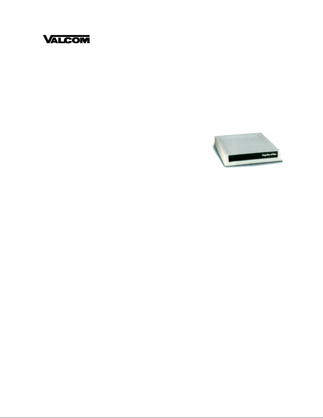
PagePac
®
by
PAGEPAC 6 PLUS
V-5323008
TABLE OF CONTENTS
Introduction . . . . . . . . . . . . . . . . . . . . . . . . . . . . . . . 1
Specifications. . . . . . . . . . . . . . . . . . . . . . . . . . . . .1-2
Important Safety Instructions. . . . . . . . . . . . . . . . .2-3
General Information. . . . . . . . . . . . . . . . . . . . . . . . . 3
Installing the PagePac 6 Plus With One or
Two Telephone Lines. . . . . . . . . . . . . . . . . . . . . . . 3-4
Connecting Speakers to PagePac 6 Plus . . . . . . . . 5
Options -- And How to Select Them . . . . . . . . . . . 6-7
Tones You Hear -- And What They Mean . . . . . . . 8-9
How to Adjust Page, Talkback and Music Volume. 10
Overview . . . . . . . . . . . . . . . . . . . . . . . . . . . . . . . . 10
Troubleshooting . . . . . . . . . . . . . . . . . . . . . . . . . . . .11
Technical Assistance . . . . . . . . . . . . . . . . . . . . . . . .11
FCC Regulations / CSA Information . . . . . . . . . 12-13
Secondary Circuit Protecti on. . . . . . . . . . . . . . . 13-14
Issue 1
INTRODUCTION
PagePac® 6 Plus is a compact, 6-watt, voice-paging system that integrates three paging zones, each
with talkback capabi lity, into your telephone system. PagePac 6 Plus can be used with most telephone
systems, from single-line residential systems to electronic key and PBX systems.
SPECIFICATIONS
FEATURES
• Works with either one or two lines, and provides two separate paging accesses when used with two
lines
• Provides three separate paging zones, each with a 2-watt output, as well as “all call” p aging and zone
groups
• Talkback is available in all three zones
• Supports both standard (indoor) and horn (outdoor) speakers.
Compatible with voice coil speakers onl y.
• FCC and CSA approved
• Controls background music in all three zones (music must be provided from a separate source, such
as an external music source, FM tuner, a tape deck, or leased source). See Note.
• Comes with its own 12-VAC power supply and plugs into any standard 120-VAC, 60 Hz outlet
• User options are telephone dial sele cted (DTMF or Pulse)
1 947182
Page 2

Note: Those who use paging systems to rebroadcast copyrigh ted music are required to obtain licenses
from and pay fees to c opyright o wners. This usually i nvolves obt ainin g licenses and p aying fees to either
ASCAP and/ or BMI (American Society of Composers, Artist s and Producers, Broadcas t Music Inc.). It is
the user's obligation to obtain any license required and pay any fees.
Dimensions/Weight
• 9.70”W x 8.60”H x 1.50”D
( 24.64cm x 21.84cm x 3.81)
• 0.194 lbs (.087 kg)
IMPORTANT SA FETY INSTRUCTIONS
For important Secondary Circuit Protection information refer to pages 13-14.
When using your telephone equipment, basic safety precautions should always be followed to reduce
the risk of fire, electric shock and injury to persons, including the following:
1. Read and understand all instructions.
2. Follow all warnings and instructions marked on the product.
3. Unplug this product from the wall outlet before cleani ng. Do not use liquid cleaners or aerosol
cleaners. Use a damp cloth for cleaning.
4. Do not use this product n ear wat er, for example, near a bath tub, wash bowl, kitchen sink , or l aundry
tub, in a wet basement, or near a swimming pool.
5. Do not place this product on an unstable cart, stand, or table. The product may fall, causing serious
damage to the product.
6. Slots and openings in the cabinet and the back or bot tom are provided for ventilation, to protect it
from overheating, these openings must not be blocked or covered. The openings should never be
blocked by placing the product on the bed, sofa, rug, or other similar surface. This product should
never be placed near or over a radiator or heat register. This product should not be placed in a
built-in installation unless proper ventilation is provided.
7. This product should be operated only f rom the type of power source i ndicated on the marki ng label. If
you are not sure of the type of power supply to your home, consult your dealer or local power
company.
8. WARNING: RISK OF ELECTRICAL SHOCK, EQUIPMENT MUST BE PROPERLY
GROUNDED. Your equipment requires a properly grounded three-prong power receptacle for safe
operation. Have the receptacle checked by a qualified electrician before connecting this equipment.
Do not cut or remove the third (ground) prong from the power transformer. Do not use two-prong
extension cords or adapters to defeat the safety features of this equipment. If you have a two-prong
receptacle, it must be replaced with a three- prong receptacle, installed by a qualified electrician.
9. Do not allow anything to rest on the power cord. Do not locate this product where the cord will be
abused by persons walking on it.
10. Do not overload wall outlets and extension cords as this can result in the risk of fire or electric shock.
11. Never push objects of any kind into this product through cabinet slots as they may touch dangerous
voltage points or sh ort out p ar t s tha t could res ult in a ris k of fi re or el ect ric shock . Never spil l li qui d of
any kind on the product.
12. T o redu ce the ri sk of electr ic shoc k, do not di sassemble t hi s product , but take it to a qualified serv ice -
man when some service or repair work is required. Opening or removing covers may expose you to
dangerous voltages or other risks. Incorrect reassembly can cause electric shock when the
appliance is subsequently used.
2947182
Page 3
13. Unplug this product from the wall outlet and refer servicing to qualified serv ice personnel under the
following conditions:
A. When the power supply cord or plug is damaged or frayed.
B. If liquid has been spilled into the product.
C. If the product has been exposed to rain or water.
D. If the product does not op erate normall y by fol lowing the operating i nstructi ons. Adjust onl y thos e
controls, that are covered by the operating instructions because improper adjustment of other
controls may result in damage and will often require extensive work by a qualified technician to
restore the product to normal operation.
E. If the product has been dropped or the cabinet has been damaged.
F. If the product exhibits a distinct change in performance.
14. Avoid using a telephone (other than a cordless type) during an electrical storm. There may be a
remote risk of electric shock from lightning.
15. Do not use the telephone to report a gas leak in the vicinity of the leak.
SAVE THESE INSTRUCTIONS.
GENERAL INFORMATION
Please adhere to the following precautions:
1. Never install telephone wiring during a lightning storm.
2. Never install telephone jacks in wet locations unless the jack is specificall y designed for wet
locations.
3. Never touch uninsulated telephone wires or termi nals unless the telephone line has been
disconnected at the network interface.
4. Use caution when installing or modifyi ng telephone lines.
INSTALLING THE PAGEPAC 6 PLUS WITH ONE OR TWO TELEPHONE
LINES
ZONE 1 SPEAKERS
TO
CENTRAL
OFFICE
MUSIC SOURCE
TO AC W ALL
OUTLET
SECO NDARY
PRO TECTO R(S)
LIN E 1
LIN E 2
CONNECTOR
BLOCK
1
W1
PAGEPAC 6 PLUS
MUSIC
J3 J 2
VOLUME
PWR M USIC
HALF-MODULAR
CORD
TO
TEL.CO .
J4
1
TO
PHONES
J5
J6 J7 J8
CONNECTOR
BLOCK
2
ZONE S
2
3
. . . . . T O E X T E N S IO N S
. . . . . T O E X T E N S IO N S
Figure 1. PagePac 6 Plus -- Typical Installation
ZONE 2 SPEAKERS
ZONE 3 SPEAKERS
3947182
Page 4
Installation Procedure
T
C
O
1. Connect PagePac® 6 Plus to the incoming telephone line(s). Connections are shown in Figure 2.
2. Connect PagePac 6 Plus to line jack(s) on telephone system.
3. Connect speakers to PagePac 6 Plus with RCA-type phono plugs and “B” crimp- type wire
connectors (provided).
4. (Optional) You may connect an external music source such as a FM tuner, tape deck, leased source,
etc.
5. Connect the power supply to an AC outlet (120 VAC, 60 Hz). The LED on the PagePac 6 Plus back
panel (below the power cord) will illuminate.
NOTE: If optional music source is used, it must have a 600 Ohm less than 1 volt output to drive the
PagePac 6 Plus (usually the output that would drive an auxiliar y head set). Anything greater than this
can harm the PagePac 6 Plus and void the warranty.
Single Line—Use Line 1 Connection Only
1. Install the first connecting block and attach the incoming line(s) to the block.
2. Attach the half-modular connecting block, and connect the other end to the PagePac 6 Plus
(see Figure 2).
3. Install the second connecting block and attach the line(s) to the telephone(s).
4. Attach the second half-modular cord to this block and connect the other end to the Pagepac 6 Plus.
TYPE 42A CONNECTING BLOCK
UL 497A
SECONDARY
PROTECTORS
LINE 1
O
ENTRAL
FFICE
LINE 2
WRAP UNUSED WIRE
AROUND CABLE
G
GREEN
B
BLACK
LINE 2
GREEN
RED
RED GREEN
HALF MODULAR CORD
YELLOW
LINE 2
RED
R
Y
Figure 2. Attaching the Half-Modular Cord
TP PAGEPAC 6 PLUS
"TO TEL. CO. J4"
4947182
Page 5
CONNECTING SPEAKERS TO PAGEPAC 6 PLUS
WARNING: DO NOT USE 70 VOLT SPEAKERS! USE PAGEPAC VOICE COIL SPEAKERS!
Both standard speakers (indoor c one-type) and hor n speakers may be used with PagePac® 6 Plus. Use
only the type speaker recommended for your situation, and do not exceed the number of speakers or
speaker run length maximums shown in Table 1.
Table 1. Speaker Limitations
Standard Indoor Speakers
(Voice Coil Only)
Horn Speakers
(Voice Coil Only)
Total Speakers 18 (maximum 6 per zone) 3 (maximum 1 per zone)
Speakers Per Run* 4 1
Maximum Length of Speaker
600 Feet 300 Feet
Run (24 AWG Wire)
*A run is a line of one or more speakers that connects directly to PagePac 6 Plus.
NOTE: If using both horns and standard speakers in the same zone, each horn counts as six
standard speakers.
NOTE: Maximum six-wall or ceiling speakers or one horn speaker per zone.
Installation Procedure
1. Install the speakers according to the directions supplied with them.
2. Connect each zone to the appropriate ZONES jacks on the PagePac® 6 Plus (see above).
Special Notes
• Use RCA-type plug adapters (3) supplied with unit, to prepare speaker cable for connection to zone
jacks.
• This Valcom equipment requires a properly grounded three-pro ng AC power re ceptacle for safe
operation. Have the receptacle checked by a qualifi ed electrician before connecting this equipment.
Do not cut or remove the third (ground) prong from the power cord. Do not use two-wire ext ension
cords or adapters to defeat the safety features of this equip ment. If you have a two-prong recept acle,
it is very important to have it rep laced with a three-prong receptacle, instal led by a qualified
electrician.
• Whenever possible, the PagePac 6 Plus should be plugged into the same recep tacle as the voice
system.
• The PagePac 6 Plus is designed to drive a 45 Ohm load.
5947182
Page 6

OPTIONS -- AND HOW TO SELECT THEM
You may select the following options for your PagePac 6 Plus.
• Zone Paging—PagePac 6 Plus has three separate pagi ng zones. Each zone is a specific group of
speakers in which the page will be heard.
• Group Zones—PagePac 6 Plus allows for pagi ng over specifi c zone groups. These are availabl e by
dialing special codes (see How to Page).
• Talkback—Two-way communication betwe en the tel ephone and speakers.
• Talkback Warning Tones—These tones are heard in the loudspeakers to let people know talkback
is on. The INITIAL tone sounds once at the beginning of the page. The REPETITIVE tones should
sound every 15 or 30 seconds (your choice).
Note: When talkback is used in a noisy zone, we recommend no more than two talkback speakers be
used in that zone. This reduces the problems caused by background noise. Talkback should normally
not be used with all call paging.
• Confirmation Tone—A single tone heard in the telephone that indicates you can page (see Tone
You Hear — And What They Mean for a list of tones).
• Background Music—You must provide a source of music. Use an external music source such as a
FM tuner, tape deck, leased source, etc.
• Automatic Outside Line Access—Connects you to the telephone line without dialing 9. You will
have to wait either 2, 4, or 10 seconds depending on the option selected. The option may also be
turned off.
The bottom panel of the PagePac® 6 Plus contains FCC information, and programming dial codes, as
well as paging and talkback volume controls (see Figure 3). The music volume control and all
connections are on the back panel (see Figure 3).
B O T T O M V IE W
MANUFACTURED BY
PagePac 6 Plus
H A R R IS C O R P ./ D R A C O N D IV IS IO N ,C a m ar illo , C A 9 3 0 1 2
TO RED UCE TH E RISK OF FIRE OR ELECTICAL SH OCK DO NO T
WARNING:
EXPOSE THIS APPLIANCE TO RAIN OR MOISTURE
TO REDUCE THE RISK OF ELECTICAL SHOCK DO NOT REMOVE COVER.
CAUTION:
NO USER SERVICABLE PARTS INSIDE. REFER SEVICING TO QUALIFIED PERSONNEL.
SERIAL No.
V-5323008
Model No.
REV 0
22052-000
REF. NO.
PEC C ODE
XXXX-XXXX
22052-000
Val co m, Inc.
COM CODE
XXXXXXXXX
Roanoke, VA
USA
COM PLIES W ITH FCC PAR T 15, CLASS B,
COMPUTING DEVICE PURSUANT TO SUBPART J: COMPLIES WITH PART 68, FCC RULES
OF PAR T 15 OF FC C RULE S.
INPUT AU XILIARY OUTP UT PO WER
12 VAC 60 Hz. 11 VDC 100 Ma.
4.1 AMP
PROGRAMMING CODES
OPTION
Confirm ation tone O FF
C o n firm a tion to n e O N
M usic Zone 1 O N
M usic Zone 2 O N
M usic Zone 3 O N
M usic All Zones O FF
Talkback Line 1 OFF
Talkback Line 2 O FF
T a lkb a c k L in e s 1 & 2 O N
Talkback Zone 1 OFF
Talkback Zone 2 O FF
Talkback Zone 3 O FF
T a lk b a c k A ll Z o n e s O N
In itial Ta lkb a ck W a rn ing T on e O F F
Repetitive T alkback W arning Tone OFF
Both Talkback W arning Tones ON
Tim e B etw een R epet. Tones
1 5 S e c o n d s
Tim e B etw een R epet. Tones
3 0 S e c o n d s
All Zone Paging OF F
All Zone P aging ON
Automatic O utside Line Access
Line 1
O F F
2 S econds
4 S econds
1 0 S e c o n d s
Line 1
O F F
2 S econds
4 S econds
1 0 S e c o n d s
FCC REG. NO. APG9Q9-17478-P A-N
DIAL C ODES
835
835
811
812
813
814
891
892
893
ZO NE
821
822
823
824
831
832
833
841
842
851
852
ZO NE
861
862
863
864
865
866
867
868
CSA/NRTL
583 T
LISTED
COMMERCIAL AUDIO EQUIPMENT
2
VOLUME CONTROLS
2
3
3
1
LOUDSPEAKER PAG ING VO LUM E
TALKBACK LISTENING VOLUM E
1
The bottom panel of the P agePac 6 Plus
contains FCC inform ation, and program m ing
dial codes, as w ell as paging and talk-back
v o lu m e c o n tro ls . T h e m u s ic v o lu m e c o n tro l
and all connections are on the back panel.
MUSIC
J 3 J2
W1
PW R M USIC
VOLUM E
TO
TEL.CO .
J4
TO
PHON ES
J5
1
J6 J7 J8
R E A R V IE W
ZON ES
2
3
Figure 3. PagePac 6 Plus Bottom and Back Panel
6947182
Page 7

Setting Options
To select the desired option, dial the code shown.
1. Pick up the telephone and listen for PagePac 6 Plus dial tone
(on key systems, select the desired line first).
2. Dial the number for the option desired (see Table 2 or the simplified user guide supplied), and listen
for program tone (two short tones).
3. Replace the receiver.
Note: If you hear reorder tone (fast busy tone), a dialing error has been made. Hang up and start over.
Table 2 is also on the bottom of the PagePac 6 Plus chassis.
Table 2. Programming Options
Option Dial Code
Confirmation tone - OFF*
Confirmation tone - ON
Music in Zone 1 - ON
Music in Zone 2 - ON
Music in Zone 3 - ON
Music in all zones - OFF*
Talkback on Line 1 - OFF
Talkback on LIne 2 - OFF
Talkback on Lines 1 and 2 - ON*
Talkback in Zone 1 - OFF
Talkback in Zone 2 - OFF
Talkback in Zone 3 - OFF
Talkback in all zones - ON*
Initial talkback Warning Tone - OFF**
Repetitive talkback Warning Tone - OFF*
Both talkback Warning Tones - ON*
Time between Repetitive tones - 15 seconds
Time between Repetitive tones - 30 seconds*
All-zone paging - OFF
All-zone paging - ON*
Automatic Out side Line Access
LINE 1
OFF
2 sec.
4 sec.*
10 sec.
LINE 2
OFF
2 sec.
4 sec.*
10 sec.
* Indicates the default or factory-set condition for each option. If power goes off, all
options are reset to their default values.
** Check local regulations before shutting off either the Initial or Repetitive
talkback warning tones.
834
835
811
812
813
814
891
892
893
821
822
823
824
831
832
833
841
842
851
852
861
862
863
864
865
866
867
868
7947182
Page 8

TONES YOU HEAR -- AND WHAT THEY MEAN
In addition to the confirmati on tone and talk back warning tones already described, PagePac® 6 Plus has
several other tones that help you use the system.
• Dial Tone—PagePac 6 Plus dial tone indicates that you may dial the number for the desir ed paging
area.
• Regular Dial Tone—Phone company dial tone indicates that you may dial a phone number.
• Busy Tone—PagePac 6 Plus busy tone indicates that the zone you want to page is in use.
• Reorder Tone—Reorder tone is a “fast” busy tone. Dialing error. Hang up and start over.
• Program Tone—Program tone is two very short tones. You will hear it after selecting an option. It
indicates the option was successfully selected.
• Call Waiting Tone—Call waiting tone is two short tones (but longer than progr am tone). You will hear
it if a call comes in while you are paging.
PAGE DIAL CO D E S
Paging Area Dial
Zone 1 1
Zone 2 2
Zone 3 3
Zone 2 and 3 4
Zone 1 and 3 5
Zone 1 and 2 6
All Zones 7
If talkback is on, the voice of the person at the telephone controls the page/talkback switch. If this
person speaks or makes any noise, anyone using talkback will be cut off. After the person at the
telephone is quiet, it takes about one-half second for the speakers to go into talkback.
PLACING A CALL
1. Pick up the telephone and listen for PagePac 6 Plus dial tone
(on key systems, select desired line).
Note: If you hear Reorder Tone (a fast busy tone), a dialing error has been made. Hang up and start
over.
2. Dial 9, and listen for the regular dial tone. Or, you may wait for the regular dial tone. If you want the
operator, dial 0 as soon as you hear PagePac® 6 Plus dial tone.
Note: To dial emergency 911, dial 9 or wait for t he regular dial tone, and then dial 911.
3. Dial the number. Dialing 9 gives you regular dial tone immediately. If you wait, PagePac 6 Plus will
time out and then provide regular dial tone. How long this takes depends on which Automatic
8947182
Page 9

Outside Line Access time period you select unless you have selected “Off” for Outside Line Access,
in which case you will have to dial the 9.
If a call comes in while you are preparing to p age, but have not dialed the zone(s), the caller will be connected directly to your phone (with no ring).
If a call comes in while you are paging, the page will be interrupted for a moment, and you will hear Call
Waiting Tone (two short tones). Hang up, and the phone will ri ng. You may then answer the call normally.
Note: PagePac 6 Plus has an Operator Access feature. Whenever you dial “0” before selecting a paging
zone, the unit will automatically place the call to the operator.
USING LAST NUMBER REDIAL WITH PAGEPAC 6 PLUS
If your telephones have last number redial, you can use it with PagePac 6 Plus. The exact procedure
depends on whether or not your phone has a PAUSE button.
Example: Without A PAUSE Button
Note: The Automatic Outside Line Acc ess shou ld be set f or 2 seconds . (Dial option code 862 f or L ine 1,
or 866 for Line 2.)
1. Lift the telephone handset (on a key system, selec t the desi red line), and wait for the regular dial
tone. Then, dial the number.
To redial:
2. Repeat Step 1, then press the redial button on the telephone
(or on some phones, dial the redial code).
Example: With a PAUSE Button
To place initial call:
1. Lift telephone receiver and listen for PagePac 6 Plus dial tone.
2. Dial 9.
3. Press Pause button and dial number.
To redial:
1. Lift the telephone receiver, listen for PagePac® 6 Plus dial tone.
2. Press redial button (or on some phones, dial redial code).
Note: If you have problems using the “With A PAUSE Button” procedure, try the
“Without A PAUSE Button” procedure.
Note: Using PagePac 6 Plus with a PBX—To prevent unintentional pages, connect PagePac 6 Plus on a
trunk that has a normally unused access code (for example, a trunk that is accessed by dialing 8).
This trunk may also be used for outgoing and incoming calls.
9947182
Page 10

HOW TO ADJUST PAGE, TALKBACK AND MUSIC VOLUME
1
2
3
VOLUME CONTROLS
1
2
3
LOUDSPEAKER PAGING VOLUME
TALKBACK LISTENING VOLUME
ZONE
ZONE
MUSIC
VOLUME
PWR M U SIC
J3 J2
TO
TEL
J4
PAGE VOLUME CONTROLS—These control page volume in indicat ed zone ; they al so af f ect music volume in that zone. Adjust PAGE VOLUME CONTROLS before adjusting MUSIC VOLUME Control.
TALKBACK VOLUME CONTROLS—These control volume of talkback from indicated zone.
MUSIC VOLUME—This controls music volume in all zones without affecting page volume.
REAR OF UNIT
OVERVIEW
The PagePac® 6 Plus contains no user-serviceable parts, and should be repaired only by authorized
personnel. There are several types of installation and maintenance plans available from Valcom or your
dealer. For information or warranty service, call your Valcom sales representative or authorized dealer.
To adjust paging volume, turn each zones PAGE VOL control clockwise to increase or counterclockwise
to decrease volume.
If your paging system fails to oper ate properly, follow the suggestions in the “Trouble Analysis Table”
(Table 3), before calling for professional assistance.
10 947182
Page 11

TROUBLESHOOTING
Problem Corrective Action
No sound from one or more speakers
in any zone while others work.
Music does not work, but paging
does.
Do not hear page. Ensure there is power to the paging unit. LED is on.
No all-call paging. All-call is programmed.
No talkback or very low volume. Ensure talkback is programmed.
Poor talk back or noisy talk back. Ensure speaker does not run ne ar fl uorescent light fixtures, electric motors, etc.
Paging and music are garbled. Check talkback volume controls on bottom of pagi ng unit.
Unable to access outside line. Ensure outside line access dial code is programmed.
Table 3. Trouble Analysis
Check volume control on pr oblem speaker(s).
Check page vol ume control for each zone, located on the bottom of unit.
Check all connections to speakers.
Check wire to speakers.
Replace bad speaker with good one. If speaker cannot be replaced immediately,
wire around it to ensure serv ice to the remaining speakers.
NOTE: Look for a mix of voice c oil and 70 volt speakers. Replace all 70 volt
speakers with voice coil type.
Check music volume cont rol on rear of paging unit.
Adjust volume control on musi c sou r ce.
Check the programming options.
Check page volume co nt rols on bottom of unit.
Check all connections and wire.
Check for correct speakers. The correct speaker should be voice coil type only.
Connect a 2500-Type telephone to J5, to test.
Check talk back volume controls on the bottom of the unit.
Check speaker wire for shorts .
Check all connecti ons.
Ensure that there are not too ma ny speakers on w ir e run or zone.
Check to be sure outside line is connected to unit.
Check for dial tone on out side line connection.
TECHNICAL ASSISTANCE
When calling, have a VOM and a telephone test set available and call from the job site.
Call (540) 427-3900 and ask for PagePac Technical Support, or call (540) 427-6000 for Valcom 24-hour
Automated Support or visit our websites at http://www.pagepac.com and www.valcom.com.
Should repairs be necessary, attach a tag to the unit clearly stating company name, address, phone
number , contact person, and the nature of the problem. Send the unit to:
Valcom, Inc.
PagePac
5614 Hollins Road
Roanoke, VA 24019-5056
®
Repair Dept.
11 947182
Page 12

FCC REGULATIONS PERTAINING TO THIS EQUIPMENT
FCC (Part 15)
Radio Frequency Interference
The Valcom PagePac® 6 Plus generates and uses radio frequency energy and if not installed and used
in strict accordance with the manufacturer's instructions, may cause interference to radio and television
reception. Testing has been conducted for compliance with the limits for Class B device in accordance
with the specifications in Subpart J of Part 15 of the FCC Rules. This testing is designed to provide reasonable protection against such int erference. However, there is no guarantee that interference will not
occur in a particular installation. If this equipment does cause interference to radi o or television reception, which can be determined by turning the unit off and on, the user is encouraged to try to correct the
interference by one or more of the following measures:
• Reorient the radio or TV receiving ant enna.
• Relocate the PagePac 6 Plus with respect to the radio or TV receiver or vice-versa.
• Plug the PagePac 6 Plus into a different outlet so that it and the radio or TV receiver are on different
branch circuits.
• If necessary, the user should consult the dealer or an experienced radio/television technician for
additional suggestions. The use r ma y fi nd the fol lowin g bo okle t, “ How To Identify and Resolve Radio TV Interference Problems,” helpful. This booklet was prepared by the Federal Government Printing
Office, W ashington, DC 20402. Stock order No. 004-000-00345-4.
FCC (Part 68)
This equipment is registered with the Federal Communic ations Commission (FCC) in accordance with
Part 68 of its Rules. The FCC requires that the manufacturer p rovi de you with the following information:
Connection and Use with Nationwide Telephone Network
The FCC requires that you connect your telephone equipment to the nationwide telephone network
through a modular telephone outl et or jac k. The modul ar telephone outl et or j ack to which the equipment
must be connected is a USOC RJ11C.
Registered equipment may not be used with Coin Telephone Lines. Equipment may be used with Party
Lines in areas where state tariffs permit such connections and when equipment is adaptable for such
use.
Information You May Need to Supply the Telephone Company
Upon request of your local telephone company, you are required to provide them with the following
information:
1. The lines to which you will connect the telephone equipment.
2. The FCC registration number and Ringer Equivalence Number (REN). Both numbers are listed on
the equipment label. The REN is useful to determine how many devices you may connect to your
telephone line and still h a ve them ring when your telephone line is cal led. In most, but not all, areas,
the sum of all RENs per line should be 5 or less. You may want to contact your local telephone
company. The local telephone company must also be notified upon final disconnection of the
equipment from the local telephone company lines.
12 947182
Page 13

CSA INFORMATION
The Canadian equivalent of the RJ11C connector is CA11A. Where applicable, CA11A is to be understood for other references to RJ11C in this manual.
This product is CSA Certified.
In Canada, the DOC registrat ion number appears on th e maple-leaf l abel, and the Load Number is under
the maple-leaf label.
NOTICE:
The Canadian Department of Communications label identifies certified equipment. This certification
means that the equipment meets certain tel ecommunications network protective operational and safety
requirements. The Department does not guarantee the equipment will operate to the user’s satisfaction.
Before installing this equipment, users should ensure that it is permissible to be connected to the
facilities of the local telec ommuni cations company. The equipment must also be installed using an
acceptable method of connection. In some case s, the company’s inside wiring associated with a single
line individual service may be extended by means of a certifi ed connector assembly (telephone
extension cord). The customer should be aware that compliance with the above conditions may not
prevent degradation of service in some situations.
Repairs to certified equipment should be made by an autho rized Canadian maintenance facility designated by the supplier. Any repairs or alterations made by the user to this equipment , or equipment
malfunctions, may give the telecommunications company cause to request the user to disconnect the
equipment.
Users should ensure for their own protection that the electrical ground connections of the power utility,
telephone lines and internal meta llic water pipe system, if present, are connected together.
This precaution may be particularly important in rural areas.
CAUTION:
User should not attempt to make such connections
themselves, but should contact the appropriate electri
inspection authority, or electrician, as appropriat e.
13 947182
Page 14

SECONDARY CIRCUIT PROTECTION
IMPORTANT INFORMATION
This equipment is for use on telephone wiring cont aining a secondary circuit protector.
This paging equipment requires a Secondary Circuit Protector where applicable (see Figure 7).
The secondary circuit protector must be located between the primary protector and the paging equipment. Refer to the Safety Information below.
SAFETY INFORMATION
• The Secondary Circuit Protector is used when connecting paging equipment directly to telephone
lines that may be exposed to high voltage power lines.
• Never install telephone wiring during a lightning storm.
• Never install telephone jacks in wet locations unless the jack is specifically designed for wet
locations.
• Never touch uninsulated telephone wires or terminals unless the telephone line has been
disconnected at the network interface.
• Use caution when installing or modifyi ng telephone lines.
• Use appropriate Valcom approved device.
Figure 7. Example Configurations Requiring Secondary Protection When Paging Equipment
is Connected Directly to the Telephone Network
14 947182
 Loading...