

Page 1
Issue 2
TALKBACK INTERCOM SYSTEM
V-2927 CLOCK CONTROL CARD
FOR THE V-2924A
INTRODUCTION
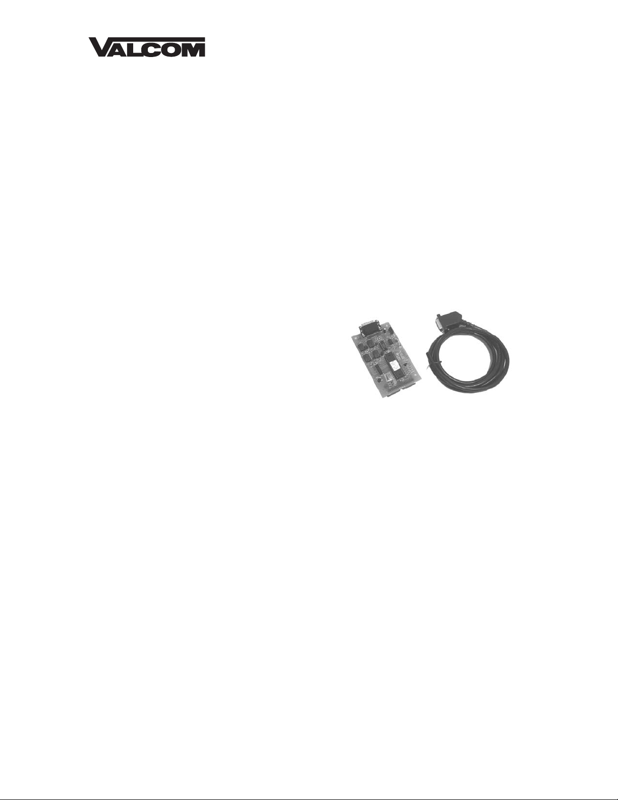
The V-2927 Clock Control Card is an optional plug-in card designed for use with the V-2924A
Talkback Intercom System with a V-2928 Option Card. It provides correction and control
functions for various impulse and synchronous clocks. The V-2927 also provides a digital output
used with the V-DCPI, Digital Clock Protocol Interface, to provide time correction data to Valcom
wired and wireless clocks. Programming of various clock types is performed via Windows
compatible Programming Tool. The V-2927 requires the use of the V-CIO Clock Interface Board
when used with mechanical time clocks.
DIMENSIONS/WEIGHT
• 5.30”L x 3.00”W x 1.10”D
(13.46cm x 7.62cm x 2.79cm)
• 0.9 lbs. (0.41 kg)
FEATURES
• Valcom Digital Output
• Two clock ports, independently programmable
• 24 mechanical clock types supported (see code list
on next page for types)
• Manual clock advance (operation dependent on clock types), dial code accessible
• Programmable adjustment for daylight savings time (DST) (operation dependent on clock
types)
• Automatic clock correction after time update
• Automatic clock correction after power disruption
• Windows Programming Tool
MINIMAL SYSTEM REQUIREMENT
• V-2924A Control Unit with V-2928 Option Card
• V-2927 Clock Control Card
• Rev 2.00 Programming Tool
• Rev 2.02 Control Unit Software
• 486 or higher personal computer with Windows 95, Windows 98 or Windows NT 4.0
operating system, 8 MB RAM, 30 meg free system disk space
• V-CIO Interface Board (for impulse clocks)
• 1 available DB9 serial communications port
1 947012
Page 2

OPERATION
The V-2927 Clock Control Card installs into connectors J3 and J4 shown in Figure 1. The output
connections are presented to the V-CIO Clock Interface Board via P2, DB15 male of the V-2927
Clock Control Card. Two independent clock ports, consisting of two normally open contacts
each, are provided. These ports work independently of each other and allow the system to
control two clock types simultaneously. A status LED is provided for each relay to indicate
activity. An administrative code, (#97XX, with XX being number of minutes to advance), is
provided to manually correct or advance various impulse clocks.
(Default code is 01).
INSTALLATION
The V-2927 must be installed prior to programming its available options.
WARNING: Disconnect main power before servicing
• Remove the side plate and top cover of the Control Unit and set aside
• Remove and discard plate covering connector port opening for Clock Card DB15
• Remove four standoff nuts from Option Card
• Install 4 standoffs (shown in Figure 1)
• Connect J1 of Clock Card to J3 (shown in Figure 1)
• Connect J2 of Clock Card to J4 (shown in Figure 1)
• Press Clock Card firmly in place to make sure connectors are seated properly
• Install and tighten 4 standoff nuts on V-2927 board
• Replace top cover and side plate of the Control Unit and plug in the power supply
• Plug Clock Card connector into P2 (Clock Card Connector Port - See Figure 1 for location)
• Make connections to V-CIO board if mechanical clocks are being used (See Figure 2 for
location)
!
CLOCK TYPE CODES
Code Description Code Description
01
02
03
04
05
06
07
08
09
10
11
12
Valcom Sync-wired 12-hour
Simplex sync-wired 24-hour
Generator start
Simplex 59
Utility impulse
European reverse
Honeywell Faraday
National time, hourly
Rauland, national time, 12-corr
Stromberg
Simplex, dual motor, 45
Simplex, dual motor, 59
th
minute
th
minute
th
minute
13
14
15
16
17
18
19
20
21
22
23
24
Cincinnati D6
Cincinnati D3
Stromberg, 58
Standard electric time, FMT
Standard electric time, AR2
Standard electric time, AR3A
Dukane 24A
Dukane 240. 24 hour
Dukane 240. 12 hour
Standard electric GR
Simplex 1.8" digital 12-hour
Simplex 1.8" digital 24-hour
th
TECHNICAL ASSISTANCE
When trouble is reported, verify that power is being supplied to the unit and there are no broken
connections. Check voltages for proper polarity on the cross connect block.
Assistance in troubleshooting is available from the factory. When calling you should have a VOM
and a test set and be calling from the job site. Call (540) 563-2000 and press 1 for Technical
Support or visit our website at http://www.valcom.com.
Valcom equipment is not field repairable. Valcom, Inc. maintains service facilities in Roanoke,
VA. Should repairs be necessary, attach a tag to the unit clearly stating company name, address,
phone number, contact person and the nature of the problem. Send the unit to:
Valcom, Inc.
Repair and Return Dept.
5614 Hollins Road
Roanoke, VA 24019-5056
2
Page 3
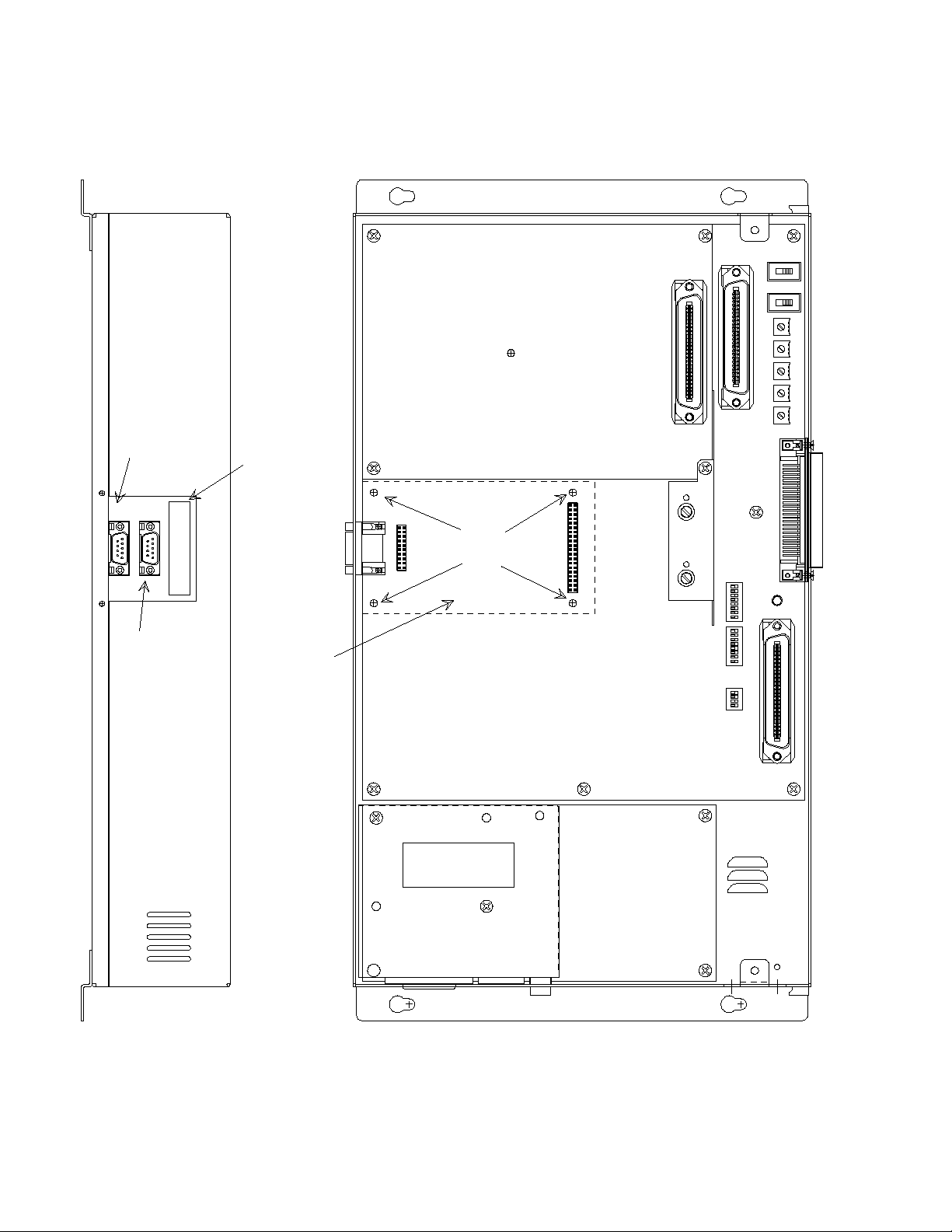
FIGURE 1 - CLOCK CARD PLACEMENT ON THE CONTROL BOARD
Top View
Side View
RS232 Serial Port
for SMDR (DB9
Connector)
P10
P1
P2
PC Programming
Port (located on
Option Board)
Clock Control
Card Port
(located on
Clock Card DB15 Connector)
Remove and
discard plate
covering
connector port
Clock Card
positions
directly over
the Option
Board
J4
Install
Standoffs
Here
J1 and J2 are located on the under
side of the Clock Card
HIGH VOLTAGE AREA
DISCONNECT POWER
BEFORE SERVICING
J3
Align J1 on the Clock Card directly over J3.
Align J2 on the Clock Card directly over J4.
Press V-2927 firmly in place.
3
Page 4
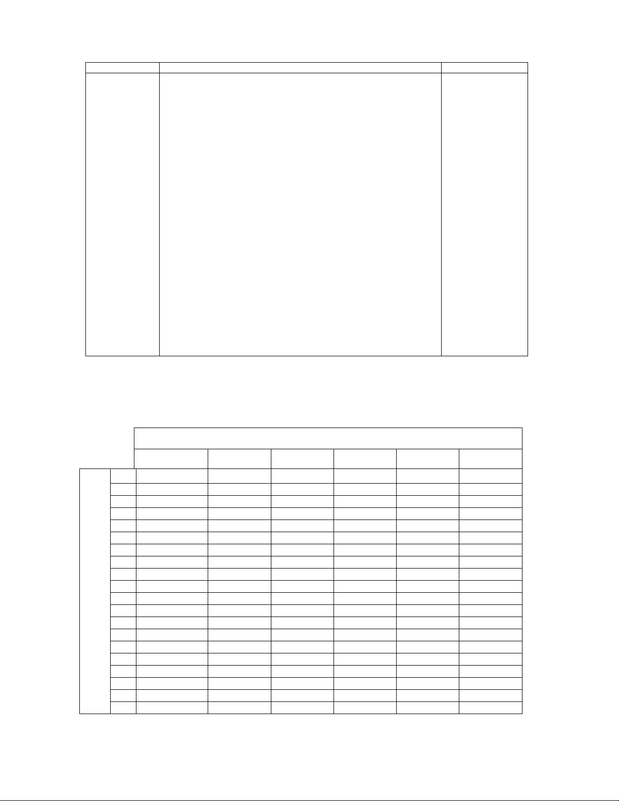
CLOCK TYPE CODES
Type # Description Figure #
1
1
2
3
4
4
5
6
7
8
9
10
11
12
13
14
15
16
17
18
19
20
21
22
23
24
Valcom Sync-wired 12-hour
TED Systems A1000M & D1000
Simplex/Edwards Sync-wired 24-hour
Simplex Generator Start (12 hour & Hourly Correction)
Simplex/IBM Impulse, 3 Wire, 58th or 59th Minute
Simplex Impulse, 2 Wire, 59th Minute Ref
Utility Impulse 12VDC or 24VDC (Non-Corrective)
European Duplex Reverse Polarity (24VDC or 48VDC)
Honeywell Faraday (1300 Series) / Cincinnati (D Synchronous)
National Time Hourly
Rauland, National Time, 12 Hour Correction
Stromberg (Synchronous, 56th Minute Ref, Electronic)
Simplex, dual Motor, 45th Minute Ref
Simplex, dual Motor, 59th Minute Ref
Cincinnati D6 (Impulse, 12 Hour Correction)
Cincinnati D3 (Impulse, 59th Minute Ref)
Stromberg (Impulse, 58th Minute Ref)
Standard Electric Time FMT-Dual Motor Couch C542014 through
C452019; C452133 through 452145
Standard Electric Time, AR2, Impulse, 59th Minute ref
Standard electric Time, AR3A, Impulse, 60th Minute Ref
Dukane 24A, 24 Hour Correction
Dukane 240, 24 Hour Correction
Dukane 240, 12 Hour Correction
Standard Electric GR Sync 12 Hour Correction
Simplex 1.8” digital 12 Hour
Simplex 1.8” digital 24 Hour
3
17
3
9
13
14
12
11
3
3
3
3
5
5
6
6
6
4
8
7
10
3
3
3
15/16
15/16
Simplex 6333 Series LED Load Chart
14 AWG 16 AWG 18 AWG 20 AWG 22 AWG 24 AWG
2
4 2480’ 1555’ 978’ 625’ 391’ 240’
6 1653’ 1036’ 625’ 417’ 260’ 160’
8 1240’ 777’ 489’ 313’ 195’ 120’
10 992’ 622’ 391’ 250’ 156’ 96’
12 827’ 518’ 326’ 208’ 130’ 80’
14 709’ 444’ 279’ 179’ 112’ 69’
16 620’ 389’ 245’ 156’ 98’ 60’
18 551’ 345’ 217’ 139’ 87’ 53’
20 496’ 311’ 196’ 125’ 78’ 48’
22 451’ 283’ 178’ 114’ 71’ 44’
24 413’ 259’ 163’ 104’ 65’ 40’
26 382’ 239’ 150’ 96’ 60’ 37’
28 354’ 222’ 140’ 89’ 56’ 34’
Number Of Clocks
30 331’ 207’ 130’ 83’ 52’ 32’
32 310’ 194’ 122’ 78’ 49’ 30’
34 292’ 183’ 115’ 74’ 46’ 28’
36 276’ 173’ 109’ 69’ 43’ 27’
38 261’ 164’ 103’ 66’ 41’ 25’
40 248’ 155’ 98’ 63’ 39’ 24’
4960’ 3109’ 1956’ 1250’ 781’ 481’
4
Page 5

FIGURE 2
V-CIO CLOCK INTERFACE
BOARD CONNECTIONS
V-CIO
V-2927
DB15
P2 CLOCK
CONTROLS
10
11
12
13
14
15
NO1
REL1
K1
NC1
NO2
K2
K1
K2
REL2
NC2
+24V
GND
CKT1
CKT2
CKT3
CKT4
NO3
REL3
NC3
NO4
REL4
NC4
TO V-C6124P
POWER
1
9
2
3
4
5
6
7
8
SUPPLY
CLOCK CIRCUIT 1
P2
P1
CLOCK CIRCUIT 2
P3
DIGITAL OUT+
DIGITAL OUT-
V-2927 CLOCK CONTROL CONNECTIONS
PIN # FUNCTION WIRE COLOR
1
2
3
4
5
6
7
8
9
10
11
12
13
14
15
NOT USED
NOT USED
DIGITAL OUT+
DIGITAL OUTNOT USED
NOT USED
CLK 1 K1 C
CLK 1 K1 N/O
CLK 1 K4 C
CLK 1 K4 N/O
CLK 2 K3 C
CLK 2 K3 N/O
CLK 1 K2 C
CLK 2 K2 N/O
GND
BLACK
WHITE
RED
GREEN
ORANGE
BLUE
WHITE/BLACK
RED/BLACK
GREEN/BLACK
ORANGE/BLACK
BLUE/BLACK
BLACK/WHITE
RED/WHITE
GREEN/WHITE
BLUE/WHITE
GND
EACH CLOCK I/O P.C. BOARD CAN SUPPORT 2 CLOCK CIRCUITS: CLK 1 AND CLK 2.
EACH CIRCUIT CONSISTS OF TWO RELAYS K1 AND K2: FORM C CONTACTS RATED 10A @ 30VDC/10A @125VAC
WARNING: DO NOT ATTEMPT TO OPERATE CLOCKS DIRECTLY FROM MASTER CLOCK BOARD!
CONTACTS OF RELAYS ON MASTER CLOCK BOARD ARE NOT PROTECTED.
5
Page 6

Valcom, Inc. warrants its products to be free from defects in materials and workmanship under conditions of normal use and service
VALCOM LIMITED WARRANTY
for a period of one year from the date of shipment. The obligation under this warranty shall be limited to the replacement, repair or
refund of any such defective device within the warranty period, provided that:
1. inspection by Valcom, Inc. indicates the validity of the claim;
2. the defect is not the result of damage, misuse, or negligence after the original shipment;
3. the product has not been altered in any way or repaired by others and that factory sealed units are unopened
4. freight charges for the return of products to Valcom are prepaid;
5. all units 'out of warranty' are subject to a service charge. The service charge will cover minor repairs
This warranty is in lieu of and excludes all other warranties, expressed or implied and in no event shall Valcom, Inc. be
liable for any anticipated profits, consequential damage, loss of time or other losses incurred by the buyer in connection
with the purchase, operation or use of the product.
This warranty specifically excludes damage incurred in shipment. In the event a product is received in damaged condition, the
carrier should be notified immediately. Claims for such damage should be filed with the carrier involved in accordance with the
F.O.B. point.
(a service charge plus parts and labor will be applied to units defaced or physically damaged);
(major repairs will be subject to additional charges for parts and labor).
Headquarters:
Valcom, Inc.
5614 Hollins Rd
Roanoke, VA 24019
Phone: (540) 563-2000
FAX: (540) 362-9800
6
Page 7

78910111213
Page 8

Page 9

Page 10

Page 11

Page 12

Page 13

 Loading...