

Page 1
VSP-V-2000
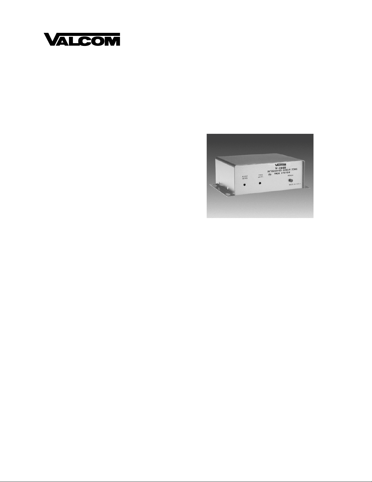
V-2000
INTEGRATED SINGLE ZONE PAGE CONTROL UNIT
INTRODUCTION
The V-2000 is an Integrated Single Zone Paging
Control Unit for use with any electronic key or
PABX. The control unit provides external power (12
Valcom power units) for powering Valcom One-Way
Amplified Speakers.
These instructions contain the specifications and
information necessary to install, operate, and maintain
the Integrated Single Zone Paging Control Unit.
Issue 6
"WARNING: To reduce the risk of fire or
electric shock, do not expose this ap pliance
to rain or moisture."
"WARNING: Shock Hazard - Do Not Open."
"AVIS: Risque de Choc Electrique ne pas
Ouvrir."
"PELIGRO: Corriente Elecrica - No Abra."
SPECIFICATIONS
Purpose
• Provides telephone system access to a single
zone of one-way paging.
Applications
• Electronic Key Systems
• PABXs
• 1A2 Key Systems (400 type line card required)
• Stand Alone Systems
Refer to Figure 1 for a block diagram of a typical
installation.
Features
• Electronic key system line key access
• PABX loop start trunk port access
• Page port access
• Switchable battery feed for loop start operation
• RJ11 for Tip and Ring connections
• Power on LED
• Drives up to 150 Valcom one-way amplified
speaker assemblies (audio)
• Background music input
• Voice operated switch to mute music during page
• Screw terminals provided for all connections
• UL Listed
• Supplies 12 Valcom power units for powering
Valcom one-way amplified speakers
• May be used with 25 or 70 volt amplifiers
• AC powered
• AC input fused at .5 amp
Capacity
• The V-2000 is a one zone single talkpath unit.
• Each V-2000 will drive up to 150 Valcom
One-Way amplified speaker assemblies (audio)
and provides 12 Valcom power units for
powering the speaker amplifier assemblies. (The
V-2000 can also be used
conventional amplifiers)
to access 25 or 75 volt
1 947200
Page 2

VALCOM ONE-WAY
AMPLIFIED SPEAKERS
V-2000
E-KEY
OR PABX
NOTE; Additional power supplies required for large numbers of speakers.
INTEGRATED
SINGLE ZONE
PAGE SYSTEM
FIGURE 1 - TYPICAL INSTALLATION
Dimensions/Weight
• 7.75"H x 5.8"W x 2.6"D
(19.69cm H x 14.73cm W x 6.6cm D)
• 2.6 lbs. (1.18 kg)
Nominal Power Requirements
• Voltage: 115 Vac
• Current: .35 Amp
Environment
• Temperature: 0 to 40 Degrees C
• Humidity: 0-85% non-precipitating
Nominal Specifications
Input Impedance: 600 Ohms
Input Level: -10dBm nominal
Music Source Input Impedance: 8 to 600 Ohms
Voice Switch Sensitivity: -21dBm
Music Input Level: -10dBm nominal
Output Impedance: 8 Ohms
Output Level: -10dBm nominal
DC Output: -24 Vdc at 600 mA
SYSTEM DESIGN
General
The Valcom V-2000 Integrated Single Zone Page
Control Unit provides access to paging from a
standard PABX loop start trunk port, an Electronic
Key System C. O. line button, or a 1A2 Key System
C. O. line button (a 400 type line card is required). In
most cases access is also possible from a PABX or
Electronic Key System page port.
Electronic Key or PABX Access
When using the V-2000 with an electronic key system
or PABX the following equipment will be needed:
1) 1 - V-2000 Integrated Single Zone Page Control
Unit
2) 1 - C. O. Line Circuit (Electronic key system) or
1 Loop Start Trunk Circuit (PABX)
3) Valcom One-Way Amplified Speaker Assemblies
(quantity and style determined by specific
installation).
Operation: Press the appropriate line key (electronic
key system) or dial the appr opriate trunk access code
(PABX). You will immediately be connected to the
paging speakers. Make announcement. The V-2000
will automatically disconnect when you hang up.
Page Port Access
When accessing the V-2000 from a page port the
following equipment will be required:
1) 1 - V-2000 Integrated Single Zone Page Control
Unit
2) Telephone system page card (if required for
external page outputs).
3) Valcom One-Way Amplified Speaker
Assemblies (quantity and style determined by
specific installation).
Operation: Follow the telephone manufacturers
directions on how to access external paging. You
will immediately be connected to the paging speakers.
Make announcement. The V-2000 will automatically
disconnect when you hang up.
Background Music
Background music may be connected to the V-2000
when using any of the above configurations. The
background music will cut off automatically when the
party making the page is speaking.
2 947200
Page 3

INSTALLATION
Precautionary Designations
CAUTION
RISK OF ELECTRIC SHOCK
DO NOT OPEN
CAUTION: To reduce the risk of electric shock,
Refer servicing to qualified service personnel.
Mounting
The V-2000 was designed for wall or table mounting.
The intended mounting orientation will render the
text on the enclosure lid legible when the unit is
viewed. When wall mounting this unit, secure it to
wall studs or a suitable brace. (A plywood backboard
2' square and at least 1/2" thick attached to wall studs
would be considered a suitable brace). Make certain
the unit is not mounted near heat sources or strong
magnetic fields. Ascertain control and terminal strip
accessibility.
Four #10 x 3/4" cross-tip round head wood screws
are included for mounting. Fasten the top two screws
at the appropriate location on the mounting surface
(approximately 3.65" apart and parallel to the floor),
allowing the screwheads to protrude 1/8" to 1/4".
Place the chassis of the unit onto the screwheads at
the mounting slots. Position the two remaining
screws and fasten through the remaining mounting
slots. Complete the mounting by tightening all
screws.
Power Connections
The V-2000 is provided with a three conductor line
cord. After all required connections have been
made, plug the cordset into appropriate AC wall
outlet.
Volume Adjustments
Located on the front cover of the V-2000 are the
screwdriver adj ustable vo lume control s for regula ting
the page and bac kground music level. Each volume
control is set by turning it clockwise to increase the
volume and counterclockwise to decrease the volume.
Do not remove cover.
No user serviceable parts inside.
This symbol indicates that dangerous
voltage constituting a risk of electric
shock is present within this unit.
This symbol indicates that there are
important operating and maintenance
instructions in the literature accompanying
this unit.
__ a. Page Level: During initial system set up, it
is recommended that the individual speaker
volume controls on the amplified speaker
assemblies be adjusted to 1/2 volume first.
Then, adjust the volume control on the
V-2000 to the desired page level.
__ b. Background music level: Adjust this
control to gi ve the desired background music
level on the paging speakers.
Wiring Instructions
(For Electronic Key System Line Button
Access or PABX Loop Start Trunk Access)
NOTE: The telephone system referred to in the
following instructions is the customer premise
equipment such as an electronic key system or a
PABX. The V-2000 CANNOT be connected
directly to a public telephone network (a central
office line).
If a modular cord is used for Tip and Ring
connections start at step ONE. For screw terminal
connections start at step TWO. (See Figure 2).
__ 1. Connect one end of a modular telephone
cord to the V-2000 RJ11 and the other end
to a vacant C. O. line position or vacant loop
start trunk on the customer premise
equipment. Go to step 4.
__ 2. Connect Tip of the vacant key system line
position or PABX loop start trunk to the Tip
screw terminal of the V-2000.
__ 3. Connect Ring of the vacant key system line
position or PABX loop start trunk to the
Ring screw terminal of the V-2000.
__ 4. Connect Tip of the one-way amplified
speakers to one of the screw terminals
marked Signal Out on the V-2000.
__ 5. Connect Ring of the one-way amplified
speakers to the remaining Signal Out screw
terminal on the V-2000.
__ 6. Connect the –24 Vdc terminal or lead of the
one-way amplified speakers to the –24 Vdc
screw terminal of the V-2000.
__ 7. Connect the GND terminal or lead of the
one-way amplified speakers to the GND
screw terminal of the V-2000.
NOTE: The Valcom V-2000 provides external
power of 12 power units (600 mA of –24 Vdc) to
operate Valcom one-way amplified speakers.
Additional power supplies are required for a quantity
of speakers using power over the 12 power units.
When using additional power supplies, make
certain:
3 947200
Page 4

1) The –24 Vdc outputs are not connected to
each other;
2) Each one-way amplified speaker is
connected to only one power source.
__ 8. Set battery feed slide switch to the "ON"
position on the V-2000.
__ 9. Plug in the power cord.
Wiring Instructions
(For connection to a Telephone System Page Port)
(See Figure 3)
__ 1. Connect one side of the page port audio
output of the telephone system to the Tip
screw terminal of the V-2000.
__ 2. Connect the other side of the page port audio
output to the Ring screw terminal of the
V-2000.
__ 3. Connect Tip of the one-way amplified
speakers to one of the screw terminals on the
V-2000 marked Signal Out.
__ 4. Connect Ring of the one-way amplified
speakers to the remaining Signal Out screw
terminal on the V-2000.
__ 5. Connect the –24 Vdc terminal or lead of the
one-way amplified speakers to the –24 Vdc
screw terminal of the V-2000.
__ 6. Connect the GND terminal or lead of the
one-way amplified speakers to the GND
screw terminal of the V-2000.
NOTE: The Valcom V-2000 provides external
power of 12 power units (600mA of –24 Vdc) to
operate Valcom one-way amplified speakers.
Additional power supplies are required for a quantity
of speakers using power over the 12 power units.
When using additional power supplies, make certain:
1) The -24 Vdc outputs are not connected; 2) Each
one-way amplified speaker is connected to only one
power source.
__ 7. Set the battery feed slide switch to the
"OFF" position on the V-2000.
__ 8. Plug in the power cord.
Optional Connections
Music Connections - Connect the output of a low
level music source to the screw terminals marked
Music on the input terminal strip on the V-2000.
Adjust the music volume control on the V-2000 to the
appropriate level.
OPERATION
General
When the V-2000 is connected to a C. O. line
position or a loop start trunk port, a Tip and Ring
battery feed is provided when the battery feed switch
is in the "ON" position. The voice switching circuit
is turned on when the person making the page begins
to speak. Background music, if connected, will be
turned off and the persons voice will be present on
the output. The voice switching circuit remains on as
long as the person is speaking. When the page is
completed or the person stops speaking for more than
3 seconds, the paging circuit is turned off and
background music is restored to the output. Note:
When the V-2000 is connected to a telephone system
page port, the battery feed switch should be in the
"OFF" position. The operation of the unit is the
same.
TECHNICAL ASSISTANCE
General
When trouble is reported, verify that power is being
supplied to the unit and there are no broken
connections. Check voltages for proper polarity to
the one-way amplified speakers.
Table 1 identifies symptoms of some possible
problems with solutions. If a spare unit is available,
continue to troubleshoot by substituting the spare unit
for the suspected defective unit. Assistance in
troubleshooting is available from the factory. When
calling, you should have a VOM, several clip leads
and a telephone test set available and be calling from
the job site. Call (540) 427-3900 and ask for
Technical Support, or call (540) 427-6000 for
Valcom 24-hour Automated Support or visit our
website at http://www. valcom.com.
The V-2000 is not field repairable. Valcom, Inc.
maintains service facilities in Roanoke, VA. Should
repairs be necessary, attach a tag to the unit clearly
stating your company name, add ress, phone number,
contact person and the nature of the problem. Send
the unit to:
Valcom, Inc.
Repair and Return Dept.
5614 Hollins Road
Roanoke, VA 24019-5056
4 947200
Page 5

RJ11
TIP &
RING
RJ11
TELEPHONE SYSTEM C. O. LINE POSITION
OR LOOP START TRUNK PORT
BATTERY
FEED
RING
TIP
MUSIC
GND
-24VDC
SIGNAL
OUT
OFF
ON
GND
-24VDC
RING
TIP
OR
TIP
RING
OPTIONAL BACKGROUND
MUSIC SOURCE
VALCOM ONE-WAY AMPLIFIED SPEAKERS
FIGURE 2 - ELECTRONIC KEY SYSTEM LINE BUTTON ACCESS OR
PABX LOOP START TRUNK ACCESS
RJ11
TIP &
RING
BATTERY
FEED
RING
TIP
MUSIC
GND
-24VDC
SIGNAL
OUT
OFF
ON
OPTIONAL BACKGROUND
MUSIC SOURCE
GND
-24VDC
RING
TIP
VALCOM ONE-WAY AMPLIFIED SPEAKERS
FIGURE 3 - PAGE PORT ACCESS
TIP
RING
5 947200
Page 6

TABLE 1
TROUBLESHOOTING CHART
SYMPTOM PROBABLE CAUSE AND SOLUTION
1. No output to speakers. a. Check for the presence of audio on the page output of the V-2000
during a page using a test set. Refer to connection information.
b. Check AC line fuse on V-2000.
2. No music output. a. Using a test set, check for music on the music input terminals.
Valcom, Inc. warrants its products to be free from defects in materials and w orkmanship under conditions of normal use and service
VALCOM LIMITED WARRANTY
for a period of one year from the date of shipment. The obligation under this warranty shall be limited to the replacement, repair or
refund of any such defective device within the warranty period, provided that:
1. inspection by Valcom, Inc. indicates the validity of the claim,
2. the defect is not the result of damage, misuse, or negligence after the original shipment .
3. the product has not been altered in any way or repaired by others and that factory sealed units are unopened (A service
4. freight charges for the return of products to Valcom are prepaid,
5. all units ‘out of warranty’ are subject to a service charge. The service charge will cover minor repairs (Major repairs will be
This warranty is i n lieu of and excludes all other warranti es, expressed or implied, and in n o event shall Valcom, Inc. b e
liable for any anticipated profits, consequential damages, loss of time or other losses incurred by the buyer in connection
with the purchase, operation, or use of the product.
This warranty specifically excludes damage incurred in shipment. In the event a product is received in damaged condition, the
carrier should be notified immediately. Claims for such damage should be filed with the carrier involved in accordance with the
F.O.B. point.
charge plus parts and labor will be applied to units defaced or phy sically damaged),
subject to additional charges for parts and labor).
Headquarters: In Canada
Valcom, Inc. CMX Corporation
1111 Industry Avenue 35 Van Kirk Drive #11 and 12
Roanoke, VA 24013 Brampton, Ontario L7A1A5
Phone: (540) 427-3900 Phone: (905) 456-1072
FAX: (540) 427-3517 FAX: (905) 456-2269
6 947200
 Loading...