

Page 1
TECHNICAL ASSISTANCE
When trouble is reported, verify there are no broken connections to the unit.
Assistance in troubleshooting is available from the factory. When calling, you
should have a Volt-Ohm meter and a lineman's test set available and be calling from
the job site. Call (540) 563-2000 and ask for Technical Support, or call (540) 767-1555
for Valcom 24-hour Faxback System or visit our website at http://www.valcom.com.
Valcom equipment is not field repairable. Valcom, Inc. maintains service facilities in
Roanoke, VA. Should repairs be necessary, attach a tag to the unit clearly stating
your company name, address, phone number, contact person and the nature of the
problem. Send the unit to: Valcom, Inc.
Repair and Return Dept.
5614 Hollins Road
Roanoke, VA 24019-5056
VALCOM LIMITED WARRANTY
Valcom, Inc. warrants its products to be free from defects in materials and workmanship under
conditions of normal use and service for a period of one year from the date of shipment. The
obligati on under this warranty shall be limited to the replacement, repair or refund of
any such defective device within the warranty period, provided that:
1. inspection by Valcom, Inc. indicates the validity of the claim;
2. the defect is not the result of damage, misuse or negligence after the original shipment;
3. the product has not been altered in any way or repaired by others and that factory sealed
units are unopened (A service charge plus parts and labor will be applied to units
defaced or physically damaged);
4. freight charges for the return of products to Valcom are prepaid;
5. all units 'out of warranty' are subject to a service charge. The service charge will cover
minor repairs (Major repairs will be subject to additional charges for parts and labor).
This warranty is in lieu of and excludes all other warranties, expressed or implied, and in no
event shall Valcom, Inc. be liable for any anticipated profits, consequential damages, loss of
time or other losses incurred by the buyer in connection with the purchase, operation or use
of the product.
This warranty specifically excludes damage incurred in shipment. In the event a product is
received in damaged condition, the carrier should be notified immediately. Claims for such
damage should be filed wi th the carrier involved in accordance with the F.O.B. point.
TROUBLESHOOTING CHART
SYMPTOMS ACTIONS
No audio from
speaker
Low volume
from speaker
Loud squeal
(Feedback)
Headquarters:
Valcom, Inc.
5614 Hollins Road
Roanoke, VA 24019-5056
Phone: (540) 563-2000
FAX: (540) 362-9800
1. Verify volume control is turned up (Clockwise).
2. Using a lineman's test set, check for proper audio level on Tip/A
and Ring/B leads and if necessary at the source.
1. Verify volume control is turned up.
2. Check voltage at speaker when in use (-18 to -24VDC required).
3. Using a lineman's test set, check for proper audio level on Tip/A
and Ring/B leads. It is possible some low level audio will be
heard with only one side of Tip/A and Ring/B connected.
1. Decrease volume of speaker (Counterclockwise).
2. Increase the distance between telephone and speaker.
In Canada:
CMX Corporation
35 Van Kirk Drive #11 and 12
Brampton, Ontario L7A 1A5
Phone: (905) 456-1072
FAX: (905) 456-2269
INSTALLATION INSTRUCTIONS FOR
SIGNATURE SERIESTM, HIGH FIDELITY
AMPLIFIED IN-WALL SPEAKER
MODEL NO. V-1450
Issue 5 947145
Page 2
VALCOM SIGNATURE SERIES
TM
, HIGH FIDELITY
SELF-AMPLIFIED IN-WALL SPEAKER
The Valcom Signature Series™ In-Wall Speaker, V -1450, is a high fidelity, selfamplified (6 Watt) speaker and may be used to provide one-way paging and high
quality music reproduction from any Valcom Page Control. This speaker has an
externally accessible volume control located behind the grille and is screwdriver
adjustable. The V -1450 will cover an area up to 600 square feet and should be spaced
20 feet apart. Good quality paging will be heard up to 30 feet in front of the speaker.
The V -1450 requires -24VDC, 200mA (4 Valcom power units). The speaker is available
in white and supplied with a trim ring and grille.
NOTE: No power amplifier required. Do not connect this speaker directly to a
25/70/100 Volt amplifier as damage to both the amplifier and speaker
may occur. (Recommended nominal input level to the V-1450 is 10dBm).
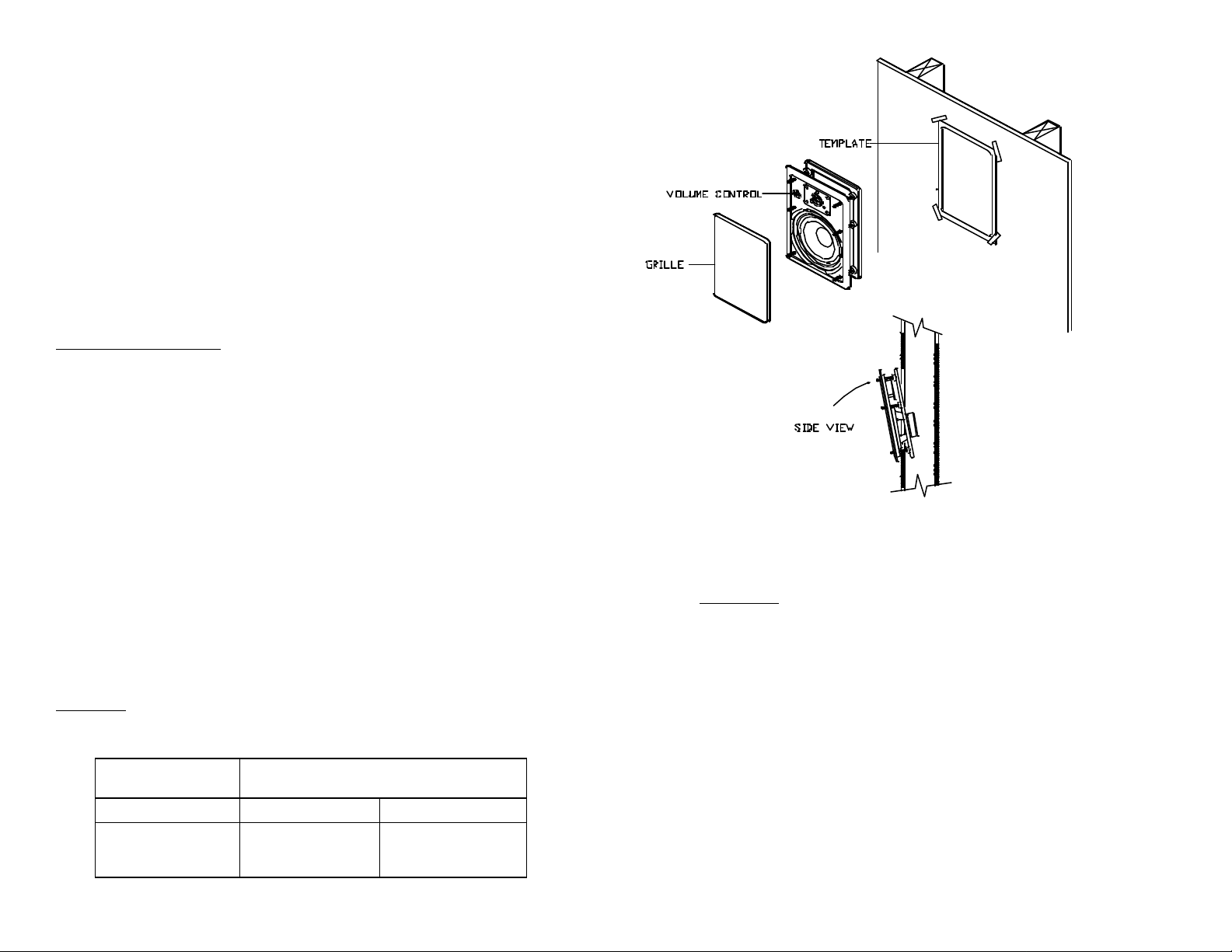
Mounting/Connections
CAUTION: Before cutting hole, identify and locate all plumbing and
electrical wiring.
Using the enclosed cutout template, mark outline of cutout on wall. Make
sure speaker is centered between any wall studs. Using the appropriate tool,
cut a hole in the wall following the template outline.
Insert a small screwdriver tip between the grill and speaker to remove grill from the
front of the speaker assembly. Assemble speaker, mounting frame and hardware as
shown in the diagram. Do not tighten frame completely.
After assembling mounting frame, make connections to the terminal block. Insert
stripped wire into appropriate term inal and tighten with screwdriver. Each connector
accepts 18 to 24AWG wire. With the tweeter on top, place mounting bracket into
hole in the wall. Push speaker assembly flush to wall and slide up 1/2 inch. Tighten
two center screws first, then tighten the remaining screws. Set volume control to 1/2
volume and test. Press grill into slot around speaker assembly.
NOTE: Exercise caution when handling speaker assembly with grill removed.
Mounting
Recommended Quantity of Speakers per Specific Power Run
(Standard Category 3 Twisted Pair Telephone Wire)
Speakers per
Power Run
V -1450
8
4
2
Wire Run Length (Feet)
24AWG
125
250
500
22AWG
200
400
800
Dimensions/Weight
• 12.00"H x 8.65"W x 3.20"D (30.48cm H x 21.97cm W x 8.13cm D)
• 3 lbs (1.36 kg)
FCC Notice
NOTE: The equipment has been tested and found to comply with the limits for
Class A digital devices, pursuant to Part 15 of the FCC Rules. These limits are
designed to provide reasonable protection against harmful interference when the
equipment is operated in a commercial environment. This equipment generates, uses
and can radiate radio frequency energy. If not installed and used in accordance with
the instruction manual, it may cause harmful interference to radio communications.
Operation of this equipment in a residential area is likely to cause harmful
interference in which case the user will be required to correct the interference at his
own expense.
NOTE: The manufacturer is not responsible for any radio or TV interference caused
by unauthorized modifications to this equipment. Such modifications could void the
user's authority to operate the equipment.
 Loading...