

Page 1
Issue 7
DUAL INPUT
ONE-WAY AMPLIFIED INTERIOR SPEAKERS
INTRODUCTION
The V-1220 and V-1222 are dual Input
One-Way Amplified Speaker assemblies for use
with any one-way or handsfree page control
unit. These speakers are for interior use only.
These instructions contain the specifications and
information necessary to install, operate and
maintain the Dual Input One-Way Amplified
Interior Speakers.
SPECIFICATIONS
Applications
• One or Two-Way Page Controls
• Electronic Key System Page Ports (interface
adapter may be required)
• PABX Page Ports (interface adapter may be
required)
• Stand Alone Systems
• Existing 70V Paging Systems
• Background music systems
Features
• Self-contained dual input amplifier and
volume controls
• 8 inch cone type speaker
• Operates on -24VDC
• All speakers wired with 3 pair station cable
• Screw terminals for all connections
Dimensions/Weight
• V-1220 - Ceiling Speaker
13.0" Dia. X 3.0" D
(33cm Dia. X 7.6cm D)
3.8 lbs. (1.73 kg)
• V-1222 - Wall Speaker
10.6"H x 9.7"W x 5.2"D
(26.92cm H x 24.63cm W x 13.20cm D)
4.4 lbs. (2.0 kg)
Nominal Specifications
• Amplifier Input Impedance
1000 Ohms Nominal
• Amplifier Input Level -10dBm Nominal
• Amplifier Output 1 Watt into 45 Ohm
speaker load
V-1220 V-1222
Power Requirements
• Voltage -24VDC
• Current 50mA
Environment
• Temperature 0 to 50 Degrees C
• Humidity 0 - 85% non-precipitating
DESIGN
The Valcom Dual Input One-Way Amplified
Interior Speakers may be used to provide
one-way paging from one-way or talkback page
controls. The speakers provide a means for
connecting one speaker to two audio sources,
making it easy to provide features such as
background music, group call, or emergency
override. These speakers can also be used to
expand existing 70V paging systems. When
power and the appropriate input signal are
applied, voice page can be made.
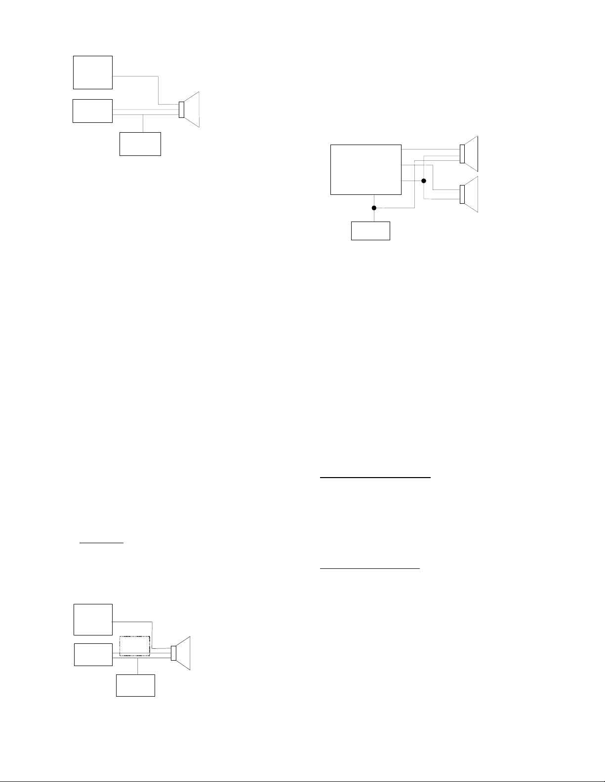
Page Control Access
When using the One-Way Amplified Speakers
with a Page Control, the following equipment will
be required:
• Appropriate one-way speaker
assembly
• Page Control
• Power Supply sized to provide
power to operate the amplified
speaker assemblies and page
control. (See Figure 1 for Page
System Block Diagram)
1 947221
Page 2
A
A
SECOND
A
A
UDIO
SOURCE
DUAL INPUT
PAGE
CONTROL
POWER
SUPPLY
FIGURE 1 - PAGE SYSTEM BLOCK DIAGRAM
ONE-WAY
MPLIFIED
SPEAKER
NOTE: When using Valcom Dual Input
One-Way Interior Speakers with a handsfree
page control, it is recommended that a V-1092
Volume Control be connected between the zone
output and the speaker input to lower the signal
level to the one-way speakers (to prevent
overdriving of inputs).
25V or 70V Paging Systems
When using the One-Way Amplified Speakers
with an existing 25 or 70V paging system, the
following equipment will be required:
• Appropriate one-way speaker
assembly
• Power supply sized to provide
power to operate the amplified
speaker assemblies
• V-1095 70 Volt Expander
Background Music
The Valcom Dual Input One-Way Amplified
Speakers may be used with a page control for
the purpose of providing background music on a
per zone basis along with one-way voice paging
(See Figure 2 for a Background Music Block
Diagram).
NOTE: When using the Dual Input One-Way
Amplified Speakers with background music and
a handsfree
recommended that a V-1094A Page Port
Preamp/Expander be connected between the
zone output and the speaker input to eliminate
backfeed of the background music to the
handsfree control unit.
MUS IC
SOURCE
page control unit, it is
Group Call
The Valcom Dual Input One-Way Amplified
Speakers may be used with a multi-zone page
control to provide simultaneous paging to a
group of zones. (See Figure 3 for a Group Call
Block Diagram).
ZONE 1
PAGE
CONTROL
ZONE 2
ZONE 8
(Group 1)
POWER
SUPPLY
FIGURE 3 - GROUP CALL BLOCK DIAGRAM
INPUT 1
INPUT 2
INPUT 1
INPUT 2
DUAL INPUT
ONE-WAY
MPLIFIED
SPEAKERS
NOTE: When using the Valcom Dual Input
One-Way Interior Speakers with a handsfree
page control, it is recommended that a V-1092
Volume Control be connected between the zone
output and the speaker input to lower the signal
level to the one-way speakers (to prevent
overdriving of inputs).
Speaker Cabling
All Valcom Dual Input Amplified One-Way
Interior Speakers require six conductor wire,
standard 22 or 24 gauge station wire is
acceptable. Shielded wire is not required or
recommended. Refer to Tables 1 and 2 when
planning a system.
Coverage
V-1220 - Ceiling Speaker: The area covered by
a ceiling speaker is determined by the height of
the ceiling. If the ceiling height is 8', the speaker
will cover approximately 250 sq. ft.; if 9 to 15',
the speaker will cover approximately 400 sq. ft.;
if 15 to 35' high, the speaker will cover
approximately 850 sq. ft.
V-1222 - Wall Speaker
an area up to 600 sq. ft. Wall Speakers should
be spaced 20 feet apart. Good quality paging
will be heard up to 30 feet in front of the
speaker.
: Wall speaker will cover
*
PAGE
CONTROL
FIGURE 2 – BACKGROUND MUSIC BLOCK
DIAGRAM
* The V-1094A is recommended when using
Handsfree Page Control
V-1094A
POWER
SUPPLY
DUAL INPUT
ONE-WAY
MPLIFIED
SPEAKER
2 947221
Page 3

g
Table 1
# of Speakers per Audio Run
Wire Run in Feet # of Speakers
100 150
200 150
400 100
800 50
1600 25
MUSIC
SOURCE
POWER
SUPPLY
DUAL INPUT
CEILING SPEAKER
INPUT 2
POWER
# of Speakers per Power
Table 2
Wire Run in Feet # of Speakers
(22 AWG)
100 30
200 30
400 15
800 7
1600 3
INSTALLATION
Page Control Access
The Valcom Dual Input One-Way Amplified
Interior Speakers provides a means for
connecting one speaker to two audio sources.
A standard paging system is made up of 3 basic
components:
• Appropriate one-way speaker assembly
• Page Control
• Power Supply sized to provide power to
operate the amplified speaker
assemblies and page control
NOTE: When using the Valcom Dual Input
One-Way Interior Speakers with a handsfree
page control, it is recommended that a V-1092
Volume Control be connected between the zone
output and the speaker input to lower the signal
level to the one-way speakers (to prevent
overdriving of inputs).
See Figure 4 for Screw Connection Location
and Designations. See Figure 5 for the required
connections when using the Dual Input
One-Way Amplified Interior Speakers with a
page control.
Input 2 Power Input 1
PAGE
CONTROL
FIGURE 5
25V or 70V Paging Systems
The Dual Input One-Way Amplified Speakers
may be used to expand an existing 25V or 70V
paging system without placing an additional load
on the amplifier by connecting one input of the
speaker directly to the 8 Ohm output of one of
the existing 70 Volt transformers tapped at 1/4
watt. A power supply will also be required.
Background Music
The Valcom Dual Input One-Way Amplified
Speaker may be used for providing background
music on a per zone basis along with one-way
voice paging. The music source is connected to
Input 2 Tip and Ring. The page zone output is
connected to Input 1 Tip and Ring.
NOTE: When using the Dual Input One-Way
Amplified Interior Speakers with background
music and a handsfree
page control unit, it is
recommended that a V-1094A Page Port
Preamp/Expander be connected between the
zone output and the speaker input to eliminate
backfeed of the background music to the
handsfree control unit.
Group Call
The Valcom Dual Input One-Way Amplified
Speakers may be used with a multi-zone page
control to provide simultaneous paging to a
group of zones. When it is used for group call,
Input 1 is connected to an assigned zone
number. Input 2 is connected to the zone
number that will be used for the group call page.
INPUT 1
NOTE: When using the Valcom Dual Input
One-Way Interior Speakers with a handsfree
page control, it is recommended that a V-1092
Volume Control be connected between the zone
Volume Control
Input 1
output and the speaker input to lower the signal
level to the one-way speakers (to prevent
overdriving of inputs).
Screw Connection Location and
nations - Figure 4
Desi
See Tables 1 and 2 for wiring specifications for
these speaker assemblies.
3 947221
Page 4

Mounting
V-1220 - Ceiling Speaker: To install speaker
assembly, measure and cut an 8-1/2" hole in
center of ceiling tile. (If using a V-9914M-5
bridge, V-9915M-5 backbox, or V-9916M bridge
and backbox, follow instructions supplied with
these assemblies).
Connect station or other suitable wire to proper
speaker terminals as labeled. Mount speaker to
ceiling tile. Ideal mounting height should be
between 7 and 23 feet.
V-1222 - Wall Speaker
bracket and mount the bracket to the wall (ideal
mounting height is 8 to 12 feet above floor level).
Connect station or other suitable wire to proper
speaker terminals as labeled. Mount speaker
on bracket.
: Unscrew the speaker
TECHNICAL ASSISTANCE
When trouble is reported, verify there are no
broken connections. Assistance in
troubleshooting is available from the factory.
Call (540) 563-2000 and ask for Technical
Support, or visit our website at
http://www.valcom.com.
Valcom equipment is not field repairable.
Valcom, Inc. maintains service facilities in
Roanoke, VA. Should repairs be necessary,
attach a tag to the unit clearly stating company
name, address, phone number, contact person,
and the nature of the problem. Send the unit to:
Valcom, Inc.
Repair and Return Dept.
5614 Hollins Road
Roanoke, VA 24019-5056
TABLE 3
TROUBLESHOOTING CHART
PROBLEM CORRECTIVE ACTION
1. No audio from speaker. 1. Make certain volume control is turned up (clockwise).
2. Check presence of -24VDC and GND.
3. Using a lineman's test set, check for the proper audio level on
the Tip and Ring leads, and if necessary also at the source.
2. Low volume from speaker. 1. Make certain volume control is turned up.
2. Check voltage at the speaker assembly when in use, -18 to
-24VDC required.
3. Using a lineman's test set, check for the proper audio level on
the Tip and Ring leads. It is possible that some low level audio
will be heard with only one side of Tip and Ring connected.
3. Loud squeal (feedback) 1. Turn down volume (counter clockwise) of speaker.
2. Increase the distance between the telephone and speaker.
3. Install a confidencer on the telephone in severe problem areas.
VALCOM LIMITED WARRANTY
Valcom, Inc. warrants its products to be free from defects in materials and workmanship under conditions of normal use and service for a period of
one year from the date of shipment. The obligation under this warranty shall be limited to the replacement, repair or refund of any such defective
device within the warranty period, provided that:
1. inspection by Valcom, Inc. indicates the validity of the claim,
2. the defect is not the result of damage, misuse, or negligence after the original shipment.
3. the product has not been altered in any way or repaired by others and that factory sealed units are unopened (A service charge plus parts
4. freight charges for the return of products to Valcom are prepaid,
5. all units ‘out of warranty’ are subject to a service charge. The service charge will cover minor repairs (Major repairs will be subject to
This warranty is in lieu of and excludes all other warranties, expressed or implied, and in no event shall Valcom, Inc. be liable for any
anticipated profits, consequential damages, loss of time or other losses incurred by the buyer in connection with the purchase, operation,
or use of the product.
This warranty specifically excludes damage incurred in shipment. In the event a product is received in damaged condition, the carrier should be
notified immediately. Claims for such damage should be filed with the carrier involved in accordance with the F.O.B. point.
and labor will be applied to units defaced or physically damaged),
additional charges for parts and labor).
Headquarters:
Valcom, Inc.
5614 Hollins Road
Roanoke, VA 24019-5056
Phone: (540) 563-2000
FAX: (540) 362-9800
4 947221
 Loading...