

Page 1
ALL CALL ONE-WAY PAGE UNIT
INTRODUCTION
These instructions provide the specifi cation s an d
information necessary to install, operate, and maintain
the V-1134, All Cal l On e- Way Page Unit.
SPECIFICATIONS
Purpose
To provide one-way all call pag e t o 34 zon es when
used with t h e V - 136R THF 36 zon e pag e con trol u n i t.
VSP-V-1134
Issue 7
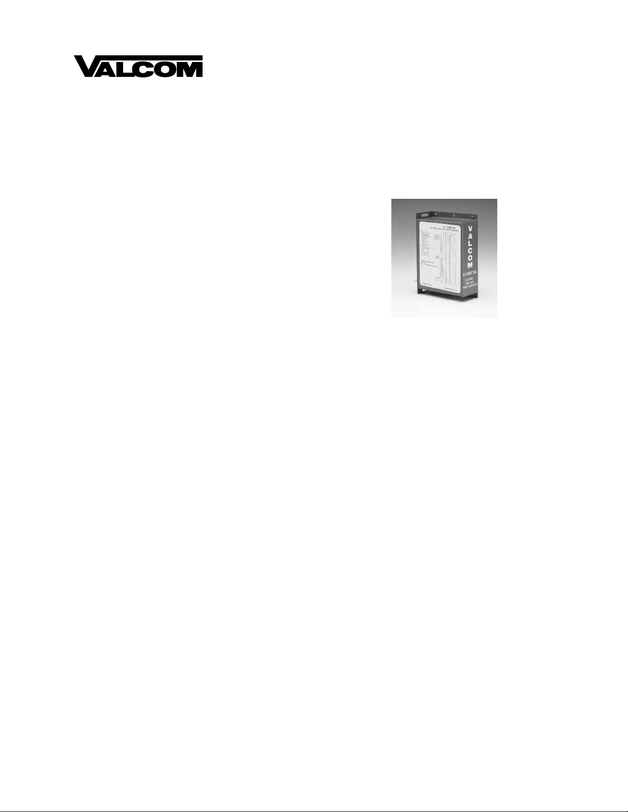
V-1134
Applications
V-136RTHF 36 zone handsfree control unit
•
Features
One-way all call am plif ication to 34 zones
•
Dial 0 for all call
•
Automatic release of all call unit with two
•
telephones off h ook
Easy installa ti on - 30" plu g en ded cable prov ided
•
Built-in volume control for all call level
•
NOTE: Unit replaces stations 0 and 39 on 36 zone
control units.
Dimensions/Weight
7.13"H x 5.75"W x 2.13"D
•
(18.11cm H x 14.61cm W x 5.41cm D)
4 lbs. (1.8 kg)
•
Power Requirements
-24 Vdc B battery 1 am p maximum
•
Output
400 milliwatts per speaker
•
DESIGN
General
This unit provides one-way all call page to the
V-136RTHF. The function s an d operat ion of the
intercom unit remain the sam e as without the all call
unit with exception th at dialing "0" energizes the all
call unit and permits a one-way page to all stations of
the intercom.
INSTALLATION
Precautions
All precautions have been taken at th e f actory to insure
that the equipment functions properly. To insure
proper operation and to prevent equi pment damage,
please observe the followin g :
a) Unplug the power supply before connecting any
wires or cables to the control unit connecting
block.
b) Do not locate the control unit more than 5 feet
from the power supply or closer than 18 inches.
c) Do not use a lamp tester to check signals, use a
voltmeter. A lamp tester when first applied is a
short circuit to electronic circuits.
d) Do not apply power to the control unit until all
connections have been dou ble- ch eck ed.
1
947114
Page 2

Mounting
Mount the V-1134 clos e to t h e V-136RTHF control
unit allowing enough room for the amphenol
connectors. NOTE: The cable supplied with the unit is
30" long. If units are s eparat ed by more than 30",
additional cable may be required.
Cabling
NOTE: In a mixed system of Bell/Buzzer and
voice signaling, stations 30-29, 0, and 5-9
must be voice signaling. Bells or buzzers
must be connected as excluded speakers
(See Figure 2).
a) In a new installation, complete all steps of the
installation procedure as shown in the instruct ions for the V-136RTHF, combination.
Connect the 25 pair intercom cable from the 66
type split block to the amph en ol on th e V- 1134
marked "to 66 block."
b) In an existing system without all call, remove the
intercom cable from the V-136RTHF and plug it
into the amphenol on the V-1134 marked "to 66
block."
c) If all speakers are to receive all call, refer to
Figure 1. One end of t h e 30" cable su ppl ie d with
the V-1134 should be plugged into the amphenol
marked "to intercom." The other end should plug
into the V-136RTHF in tercom unit.
d) If some stations are to be ex clu ded from the all
call, refer to Figure 2. Punch down two 25
pair female am ph en ol en ded cabl es on a 66 type
solid block. Plug on e cable t o the V-1134 "to
intercom" amphenol and plu g th e s econ d cable to
the V-136RTHF. Connect exclu ded s peakers t o
the appropriate ICM number on the solid block
and to the common s peaker retu rn on th e s plit
block. Connect non-exclu ded speak ers as s h own
in the V-136RTHF ins tal lat ion i n s tru ct ion .
NOTE: Do not connect speakers to stations 0
or 39.
Cross Connections
a) If using th e V-1134 with the V-136RTHF,
perform the follow i n g :
Strap the Y/BN to the G/V on t h e "to 66 block "
•
25 pair cable.
Power Connections
The V-1134 requires no external power connections as
its power is derived from the power su ppl ied t o
the V-136RTHF. Care shou l d be tak e n to make sure
that the power supply is capable of supplying the
increased current requirements when the V-1134 i s i n
use.
OPERATION
When the calling party goes off hook on the in tercom
and dials "0", the intercom switching network closes a
contact for station "0". This contact connects a
resistive ground supplied by the Y/BN lead of the
V-1134 (ICM connector) back to th e O /V l ead of t h e
V-1134 (ICM connector). The V-1134 operat es a
series of relays w ith tran sfer contacts and all stations
are transferred to the outputs of audio amplifiers. After
approximately 1 second th e amplifiers are energized
and the calling party can make a one-way page to all
stations. If station "0" is not di aled, t h e V-136RTHF
units perform in the manner described in their Valcom
System Instru ction s with the speaker leads from the
control units going straight through normally closed
contacts in the V- 1134.
TECHNICAL ASSISTANCE
When trouble is reported, v eri f y that power is being
supplied to the unit and there are no brok en
connections. Check voltages for proper polarity on the
crossconnect block. The table on t h e n ex t pag e
identifies symptoms of some possible problems with
solutions.
If a spare unit is available, continu e to trou blesh oot by
substituting the spare unit for the suspected unit.
Assistance in troubleshooting is available from the
factory. When calling, you should have a VOM, a
telephone test set, several clip leads available and be
calling from t h e job si te. C a ll (540) 427- 3900 an d as k
for Technical Support, or call (540) 427-6000 for
Valcom Aut omated Support or visit our website at
http://www.valcom.com.
The V-1134 is not field repairabl e. Val com, Inc.
maintains service facilities in Roanoke, VA. Should
repairs be necessary, attach a tag in dicatin g company
name, address, phon e n u mber, contact person, and the
nature of the problem. Send the unit to:
Valcom, Inc.
Repair and Return Dept.
5614 Hollins Road
Roanoke, VA 24019-5056
2
947114
Page 3

TROUBLESHOOTING CHART
PROBLEMS PROBABLE CAUSES AND CORRECTIONS
All call feature inoperative.
All call inhibit feature inoperative.
No all call output or low v o lu me.
All call clicks or stay s operated.
Verify connection to proper plugs on V-1134. If plugs are reversed, intercom will
operate, but all call function will not.
Plug cable from crossconnect block directly into V-136RTHF bypassing V-1134 and
check for proper operation of intercom. If V-136RTHF does not work, refer to
VSP-136RTHF instruction.
Verify straps are in place on crossconnect field as outlined previously.
Verify straps are in place on crossconnect field.
Verify that a 5K ohm resistive ground appears at the W/G (pin 28) wire of the "to 66
block" cable when two or more phones are off hook on the intercom. Refer to the
V-136RTHF instruction.
Adjust all call volume on unit to desired listening level.
Ground on a speaker wire. Remove all speaker cables at main frame. Reconnect
one at a time and test.
Split
Block
V-1134
Speakers
V-136 RTHF
To Intercom
Figure 1
Connections required from V-136RTHF to V-1134 for all call to all speakers
V-136 RTHF
Station Numbers
Figure 2
Connections required from V-136RTHF to V-1134 for all call with excluded speakers
To 66 Block
Excluded
Speakers
V-1134
To Intercom
To 66 Block
Speaker Return
Station Numbers
Split
Block
Station Numbers
Speakers
Speaker Return
3
947114
Page 4

TIP
RING
LAMPS
LAMPS SUP
INHIBIT
PC
STA 10
STA 11
STA 12
STA 13
STA 14
STA 15
STA 16
STA 17
STA 18
STA 19
STA 20
STA 21
STA 22
STA 23
STA 24
STA 25
STA 26
STA 27
STA 28
STA 29
STA 30
STA 31
STA 32
STA 33
STA 34
STA 35
STA 36
STA 37
STA 38
ALL CALL
STA 5
STA 6
CONNECT THIS SIDE TO 66 BLOCK
STA 7
STA 8
STA 9
SIG IN 1
SIG IN 2
AUX 1
AUX 2
All Call
Volume
A GND
A BATT
B GND
B BATT
Strap Y/Bn to common
side of all speakers
This unit to be used
with V-136RTHF
W/BL
BL/W
W/O
O/W
W/G
G/W
W/BR
BR/W
W/S
S/W
R/BL
BL/R
R/O
O/R
R/G
G/R
R/BR
BR/R
R/S
S/R
BK/BL
BL/BK
BK/O
O/BK
BK/G
G/BK
BK/BR
BR/BK
BK/S
S/BK
Y/BL
BL/Y
Y/O
O/Y
Y/G
G/Y
Y/BR
BR/Y
Y/S
S/Y
V/BL
BL/V
V/O
O/V
V/G
G/V
V/BR
BR/V
V/S
S/V
26
1
27
2
28
3
29
4
30
5
31
6
32
7
33
8
34
9
35
10
36
11
37
12
38
13
39
14
40
15
41
16
42
17
43
18
44
19
45
20
46
21
47
22
48
23
49
24
50
25
All Call
Inhibit
Control
All Call
Initiate
Control
NC-
26
1
27
2
28
3
29
4
30
5
31
6
32
7
33
8
34
9
35
10
36
11
37
12
38
13
39
14
40
15
41
16
42
17
43
18
44
19
45
20
CONNECT THIS SIDE TO INTERCOM
46
21
47
22
48
25
23
49
24
50
25
All Call Volume
Connection to ICM is
made via cable furnished.
VALCOM LIMITED WARRANTY
Valcom, Inc. warrants i ts products to be free from defects in material s and workmanship under conditions of normal use and
service for a period of one year from the date of shipment. The obli gation under this warranty shall be limi ted to the replacement,
repair or refund of any such defecti ve device within the warranty period, provided that:
1. inspection by Valcom, Inc. indicates the validity of the claim,
2. the defect is not the res ul t of damage, misuse, or negligence after the original s hi pment.
3. the product has not been altered in any way or repaired by others and that factory sealed units are unopened (A service
4. freight charges for the return of products to Valcom are prepaid,
5. all units ‘out of warranty’ are subject to a service c harge. The service charge will cover minor repairs (Major repairs will
This warranty is in lieu of and excludes all other warranties, expressed or implied, and in no event shal l Valcom, Inc. be
liable for any anticipated profits, consequential damages, loss of time or other losses incurred by the buyer in connection
with the purchase, operation, or use of the product.
This warranty specifically excludes damage incurred in shipment. In the event a product is recei ved in damaged condition, the
carrier should be notified immediately. Claims for such damage should be filed with the carrier involved in accordanc e with the
F.O.B. point.
charge plus parts and labor will be applied to units defaced or physic ally damaged),
be subject to additional c harges for parts and labor).
Headquarters: In Canada
Valcom, Inc. CMX Corporation
1111 Industry Avenue 35 Van Kirk Drive #11 and 12
Roanoke, VA 24013 Brampton, Ontario L7A1A5
Phone: (540) 427-3900 Phone: (905) 456-1072
FAX: (540) 427-3517 FAX: (905) 456-2269
4
947114
 Loading...