

Page 1
VSP-V-1080
Issue 3
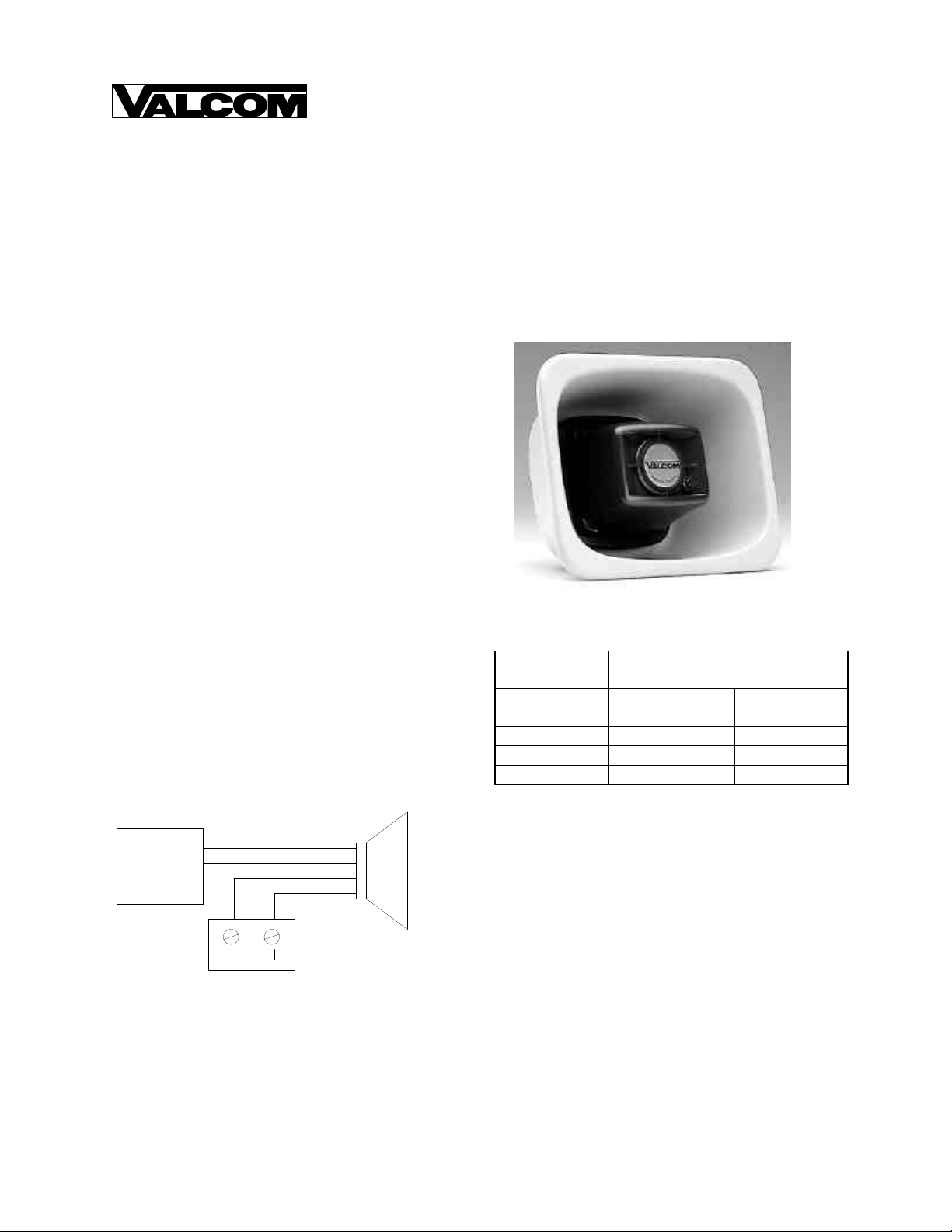
V-1080 FLEXHORN
THREE WATT ONE-WAY PAGING HORN
INTRODUCTION
The Valcom V-1080 Flexhorn is a one-way
self-amplified paging horn designed to provide voice
paging as well as background music. This horn is
weatherproof and can be used indoors or outside in
environments ranging from -20 to +55°C. A volume
control is accessible on the front of the cone. The horn
is offered in gray, beige and white.
Model V-1080-GY Gray
Model V-1080-BG Beige
Model V-1080-W White
Dimensions/Weight
• 6.80"H x 8.30"W x 3.30"D
(17.27cm H x 21.08cm W x 8.38cm D)
• 2.1 lbs. (0.95 kg)
The V-1080 requires -24VDC, 150mA (3 Valcom
Power Units) and is FCC Part 68 Registered under
BAFUSA-69358-KX-N.
CONNECTIONS
Page
Out
Valcom Page
Control
(Tip/A) Green
(Ring/B) Red
(-24VDC) White
(GND) Black
Valcom -24VDC
Power Supply
One-Way
Amplified
Speaker
NOTE: Do not connect this speaker directly to
a 25/70/100 Volt amplifier as damage to both
the amplifier and speaker may occur. A V-1095
can be used to provide an interface between a
centrally amplified speaker line and Valcom
self-amplified horns.
POWER WIRE RUN
# Horns per
Power Run
V-1080
(3 Watts)
5 250 400
2 500 800
1 760 1200
Wire Run Length (feet)
24 AWG
22 AWG
MOUNTING INSTRUCTIONS
FLUSH MOUNT
Using the template packaged with the speaker, draw the
speaker outline on the wall to be cut. Make appropriate
wiring connections and test the speaker for operation.
Using appropriate mounting screws (not furnished)
drill and mount the flange as shown.
UNIVERSAL BRACKET
Loosen or separate the universal bracket leaves by
loosening or removing the handle and hardware. Using
the back leaf as a template, mark the wall through the
mounting holes, drill and mount to the wall using
appropriate screws (not furnished) or mount directly to
a junction box.
1 947780
Page 2

Mount the T-bracket to the back of the horn as shown
using the (2) ½ inch screws provided.
"C" CLAMP FOR "I" BEAM MOUNTING
A "C" clamp is provided with the horns to allow
mounting to a beam. Place the bolt through the hole in
the bottom of the base to secure the "C" clamp to the
beam. It is suggested that the horn be mounted to the
underside of the "I" beam to provide maximum
positioning adjustments. Mount "C" clamp with (2) ½
inch screws provided.
TECHNICAL ASSISTANCE
When trouble is reported, verify the unit is properly
connected and there are no broken connections leading
to this unit. Ascertain volume control is turned up.
Assistance in troubleshooting is available from the
factory. When calling, you should have a VOM and a
test set and call from the job site. Call (540) 563-2000
for Technical Support or (540) 767-1555 for Valcom
24-hour Automated Support or visit our website at
http://www.valcom.com.
Valcom equipment is not field repairable. Valcom, Inc.
maintains service facilities in Roanoke, VA. Should
repairs be necessary, attach a tag to the unit clearly
stating company name, address, phone number, contact
person and the nature of the problem. Send the unit to:
Repair and Return Dept.
Roanoke, VA 24019-5056
TROUBLESHOOTING CHART
PROBLEM PROBABLE CAUSE AND CORRECTION
Valcom, Inc.
5614 Hollins Road
No Sound - Check volume control turned up (clockwise).
- Check presence and polarity of -24VDC and GND.
- Using a telephone test set, check for the proper audio level on the Tip and Ring
leads and if necessary also at the source.
Low Volume - Check volume control is turned up (clockwise).
- Check voltage at the horn when in use, -20 to -24VDC required.
- Using a telephone test set, check for proper audio level on Tip and Ring leads.
It is possible that some low level audio will be heard with only one side of Tip
and Ring connected.
Loud Squeal - Lower volume of horn.
- Aim horn in different direction.
- Increase the distance between the telephone and horn.
- Install a confidencer on the telephone in severe problem areas.
- Add a V-9964, Stacking Feedback Eliminator.
2
Page 3

UNIVERSAL BRACKET
SURFACE MOUNTED WITH A
UNIVERSAL MOUNTING BRACKET
"C" CLAMP FOR "I" BEAM MOUNTING
ATTACH CLAMP TO HORN ATTACH FLEXHORN TO BEAM
FLUSH MOUNT USING MOUNTING SCREWS:
UNIVERSAL BRACKET WITH CLAMP
USING THE TEMPLATE, MARK LOCATION OF
OPENING AND MOUNTING HOLES ON WALL.
DRILL HOLES APPROPRIATE TO MOUNTING
HARDWARE AND CUT OUT THE OPENING.
PENDANT MOUNTING WITH
OPTIONAL CHAIN AND
'EYE' SCREW
HOLDING FLEXHORN FIRMLY AGAINST A FLAT
SURFACE, DRILL THROUGH EACH MOUNTING BOSS
AS SHOWN.
FLUSH MOUNTING IN A STUD WALL
INSTALLED WITH MOUNTING SCREWS
OR CONSTRUCTION CEMENT.
OTHER MOUNTING OPTIONS:
OPTIONAL V-9805
VANDAL RESISTANT ENCLOSURE
3
Page 4

VALCOM LIMITED WARRANTY
Valcom, Inc. warrants its products to be free from defects in materials and workmanship under conditions of normal use and
service for a period of one year from the date of shipment. The obligation under this warranty shall be limited to the replacement,
repair or refund of any such defective device within the warranty period, provided that:
1. inspection by Valcom, Inc. indicates the validity of the claim;
2. the defect is not the result of damage, misuse or negligence after the original shipment;
3. the product has not been altered in any way or repaired by others and that factory sealed units are unopened (a service
4. freight charges for the return of products to Valcom are prepaid;
5. all units ‘out of warranty’ are subject to a service charge. The service charge will cover minor repairs (major repairs will
This warranty is in lieu of and excludes all other warranties, expressed or implied, anf in no event shall Valcom, Inc. be
liable for any anticipated profits, consequential damages, loss of time or other losses incurred by the buyer in connection
with the purchase, operation or use of the product.
This warranty specifically excludes damage incurred in shipment. In the event a product is received in damaged condition, the
carrier should be notified immediately. Claims for such damage should be filed with the carrier involved in accordance with the
F.O.B. point.
Headquarters: In Canada
Valcom, Inc. CMX Corporation
5614 Hollins Road 35 Van Kirk Drive #11 and 12
Roanoke, VA 24019-5056 Brampton, Ontario L7A 1A5
Phone: (540) 563-2000 Phone: (905) 456-1072
FAX: (540) 362-9800 FAX: (905) 456-2269
charge plus parts and labor will be applied to units defaced or physically damaged);
be subject to additional charges for parts and labor).
4
 Loading...