

Page 1
VSP-45 ohm
Issue 6
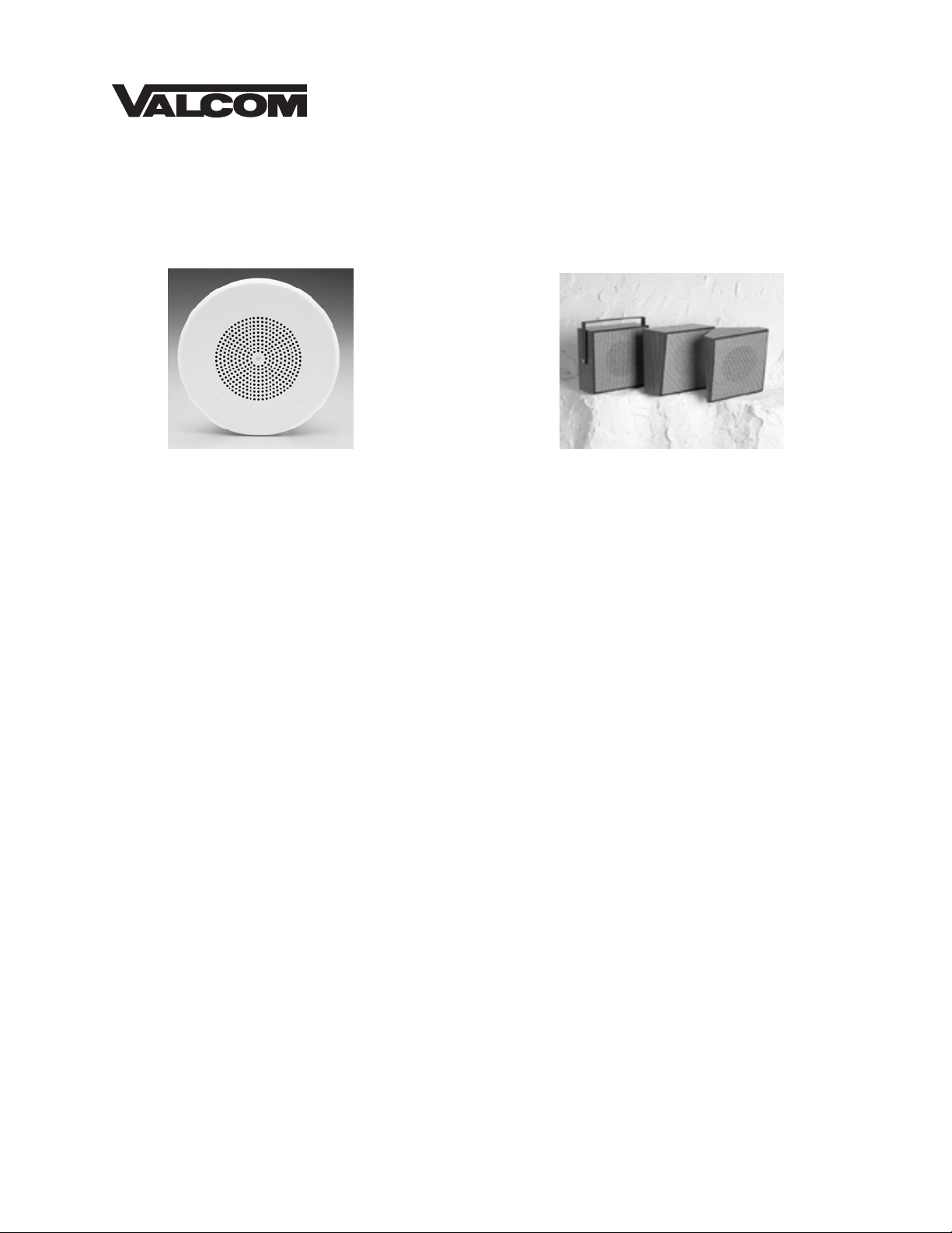
45 OHM TALKBACK INTERIOR SPEAKERS WITH LED
V-1060B V-1062B, V-1064B, V-1066B
INTRODUCTION
These instructions contain the specifications and
guidelines necessary to install, operate, and maintain
the 45 Ohm Talkback Interior Speaker Assemblies
with LED.
The 45 Ohm Talkback Interior Speaker Assemblies
with LED are for use with the Valcom "handsfree"
talkback page control units and provide both
loudspeaker and talkback functions with LED
indication in the monitor condition. These speakers
are for interior use only.
SPECIFICATIONS
Features
• 45 Ohm Impedance
• 8 Inch Speaker
• LED indicator
• Easy Hook-up (2 connections using house cable
or station wire)
Dimensions/Weights
V-1060B 8" Ceiling Speaker w/LED
13" Dia. X 2.5" D
(33.02cm Dia. x 6.35cm D)
2.4 lbs. (1.09 kg)
V-1062B Wall Speaker - wood grain with
light brown open weave grille –
10.6” H x 9.7” W x 5.2” D
(26.9cmH x 24.6cmW x 13.2cmD)
5.3 lbs. (2.41 kg)
1 947067
V-1064B Corner Speaker - wood grain with
light brown open weave grille –
10.5”H x 9.75”W x 6.3”D
(26.7cmH x 24.1cmW x 16cmD)
3.6 lbs. (1.63 kg)
V-1066B Corridor Speaker - wood grain with
light brown open weave grille -
10.3"H x 10.3"W x 4.2"D
(26.2cmH x 26.2cmW x 10.7cmD)
5.7 lbs (2.59 kg)
Power Requirements
45 mA @ -24 Vdc max (for powering the LED)
Environment
Temperature -20 to +55oC
Humidity 0-95% non-precipitating
SYSTEM DESIGN
General
The 45 Ohm Talkback Speakers are designed to be
used with the Valcom "handsfree" talkback control
units. In combination with these units, they will
provide both loudspeaker and talkback functions with
LED indication.
Page 2
A standard Valcom talkback paging system is made
up of three basic components:
1. A talkback page control unit.
2. Speakers (45 Ohm)
3. A power supply.
Although the "B" series 45 Ohm Talkback Interior
Speakers with LED can be used with all Valcom
Talkback Control Units, consult Valcom's VSP
Handsfree Talkback Paging (947100) for detailed
information on selecting the control unit and power
supply.
NOTE: Only the Valcom V-1109RTHF and V9921HF provide provisions for activating the LED.
Coverage
The distance you can be away from a speaker and
still have good talkback depends on the type of
speaker and the ambient noise level. In a typical
office environment, a wall speaker (V-1062B, V1064B, V-1066B) will cover approximately 600
square feet (talkback from 25') and a ceiling speaker
(V-1060B) will cover approximately 250 square feet
when mounted 8' from the floor (talkback from 10').
Ceiling speaker coverage is dependent on ceiling
height; the greater the ceiling height, the larger the
area covered.
IMPORTANT
The speaker is no better than your ears. If you
cannot carry on a conversation at normal voice
levels over the required talkback distance, then
the talkback page equipment will not function
satisfactorily.
Use common sense when mounting a talkback
speaker. The speaker should be as close as
possible to the area where talkback is desired.
It should not be mounted close to, or pointed at,
noise producing equipment such as fans, air
conditioners, machinery, or compressors.
Limitations
• Two talkback speakers maximum per zone
unless V-9922A talkback speaker selection units
are used. Refer to the next section for details.
• Two talkback plus 40 one-way amplified
speakers maximum per zone when mixing
talkback and one-way paging.
• 800 feet maximum cable length to speaker from
page control.
NOTE: Do not split pairs to speakers.
• Do not use talkback in noisy areas (80dB or
greater).
V-9922A Talkback Speaker Selection
Units
Valcom recommends that the total number of
speakers per talkback zone be limited to two talkback
and forty one-way self-amplified speakers. The
reasoning behind this recommendation is simple.
Whenever a page is made into a talkback zone, the
paging party will hear audio from all of the talkback
speakers in that zone. If a zone contains more than
two talkback speakers, the talkback audio from the
"extra" speakers will impede the quality of the
talkback audio from the desired speaker.
Additionally, there are limits to the number of
talkback speakers that a page control will actually
drive.
Ideally, if a page were made into a talkback zone, all
of the speakers would simply act like "one-way"
speakers except for the one that is closest to the
paged person. Talkback capability can be provided
by utilizing a V-9922A Talkback Speaker Selection
Unit for each talkback speaker. (A V-9928 Wall
Mount 5 Watt Amplifier is also required for every six
(6) talkback speakers).
When a page is made, all speakers provide one-way
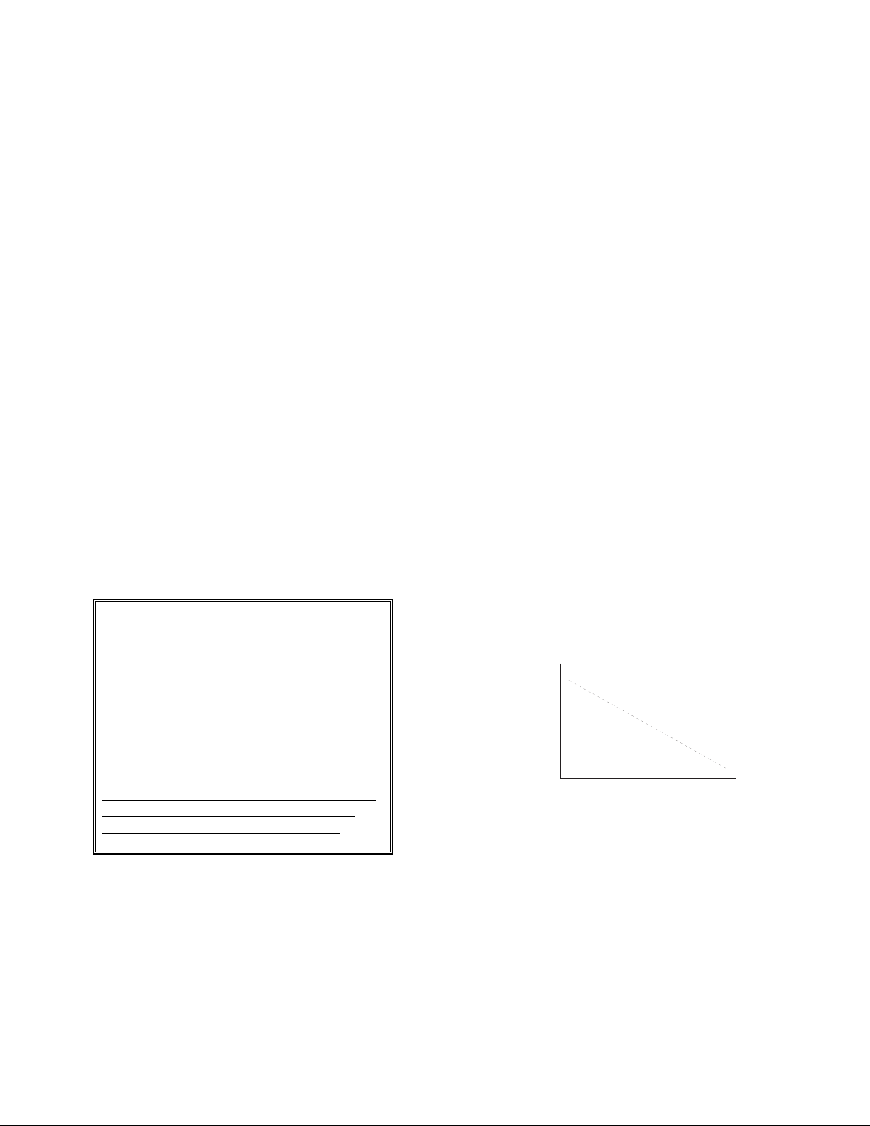
TYPICAL REPLY DISTANCE CHART
Machine
Shop
(Noisy)
Shipping
(Moderate)
Waiting
Rooms
(Quiet)
announcement. In order to respond, the paged party
activates the closest speaker with a press of the
push-button of that speakers associated talkback
speaker selection unit. This activates the chosen
speaker as a talkback speaker and resets any
previously selected speaker. Contact Valcom
Technical Support at (540) 427-3900 for additional
information.
90
80
70
60
50
Talkback not recommended above 80dB
10' 20' 30' 40' 50'
Maximum Talkback Reply Distance
2 947067
Page 3

INSTALLATION
Connections
Two conductor twisted wire is required for the 45
ohm talkback speakers. Standard 22 or 24 gauge
station wire is acceptable. Shielded wire is not
required or recommended. Connections are as
follows:
• Speaker out from page control to speaker tip.
• Speaker common to speaker ring.
• Switched –24 Vdc to –24 Vdc (LED).
• Power supply Ground to GND (LED).
Mounting
V-1060B: Cut an 8.5" dia. hole in ceiling tile. After
connections have been made to the speaker, attach
speaker to ceiling tile using the mounting hardware
provided. NOTE: Where extra speaker support is
needed, a V-9916 or V-9916M Valcom Bridge and
Backbox should be used.
V-1062B:
fasten a suitable mounting screw (#10 sheet metal
screw or similar) to the wall at the desired location
for mounting of the speaker. Hang the speaker on
the screw using the keyhole on the speaker bracket.
V-1064B:
the speaker, use appropriate hardware such as an 8d
finishing nail and hang the speaker in the corner.
Typical mounting height would be 8 feet.
After making the required connections,
After making the required connections to
V-1066B:
from speaker assembly. Using appropriate hardware,
mount the bracket to the wall. After making the
required connections, reattach the baffle to the
speaker and the speaker to the mounting bracket.
Unscrew mounting bracket and baffle
TECHNICAL ASSISTANCE
When trouble is reported, verify the unit is properly
connected and there are no broken connections
leading to this unit.
Assistance in troubleshooting is available from the
factory. When calling, you should have a volt-ohm
meter and a lineman's test set and be calling from the
job site. Call (540) 427-3900 and ask for Technical
Support, or (540) 427-6000 for Valcom 24-hour
Automated Support or visit our website at
http://www.valcom.com.
Valcom equipment is not field repairable. Valcom,
Inc. maintains service facilities in Roanoke, VA.
Should repairs be necessary, attach a tag to the unit
clearly stating company name, address, phone
number, contact person, and the nature of the
problem. Send the unit to:
Repair and Return Dept.
Valcom, Inc.
5614 Hollins Road
Roanoke, VA 24019-5056
TROUBLESHOOTING CHART
SYMPTOM ACTION
• No sound in page mode. • Check tip and ring for audio at speaker.
• Check tip and ring for audio at control unit.
• Low sound in page mode. • Check volume controls at page control.
• Poor listening in talkback
mode.
• No LED indication. • Check presence and polarity of LED input signal.
• Check talkback volume control at page control. Set
control where audio is clearly audible.
3 947067
Page 4

Valcom, Inc. warrants its products to be free from defects in materials and workmanship under conditions of normal use and service
for a period of one year from the date of shipment. The obligation under this warranty shall be limited to the replacement, repair or
refund of any such defective device within the warranty period, provided that:
1. inspection by Valcom, Inc. indicates the validity of the claim,
2. the defect is not the result of damage, misuse, or negligence after the original shipment.
3. the product has not been altered in any way or repaired by others and that factory sealed units are unopened (A service
charge plus parts and labor will be applied to units defaced or physically damaged),
4. freight charges for the return of products to Valcom are prepaid,
5. all units ‘out of warranty’ are subject to a service charge. The service charge will cover minor repairs (Major repairs will
be subject to additional charges for parts and labor).
This warranty is in lieu of and excludes all other warranties, expressed or implied, and in no event shall Valcom, Inc. be
liable for any anticipated profits, consequential damages, loss of time or other losses incurred by the buyer in connection
with the purchase, operation, or use of the product.
This warranty specifically excludes damage incurred in shipment. In the event a product is received in damaged condition, the
carrier should be notified immediately. Claims for such damage should be filed with the carrier involved in accordance with the
F.O.B. point.
Headquarters: In Canada
Valcom, Inc. CMX Corporation
1111 Industry Avenue 35 Van Kirk Drive #11 and 12
Roanoke, VA 24013 Brampton, Ontario L7A1A5
Phone: (540) 427-3900 Phone: (905) 456-1072
FAX: (540) 427-3517 FAX: (905) 456-2269
VALCOM LIMITED WARRANTY
4 947067
 Loading...