

Page 1
VSP-V -1050C
Issue 8
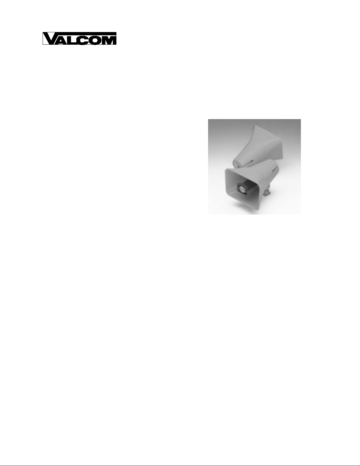
V-1050C - 5 WATT BI -DIRECTIONAL HORN/
ONE-WAY AMPLIFIER ASSEMBLY
INTRODUCTION
The V -1050C is a Bi-directional, 5 Watt One-way
Amplified Horn Assembly. The V -1050C consists of
two horn speakers positioned on a common mounting
frame with a built-in one-way 5 Watt amplifier.
SPECIFICATIONS
Features
• 5 Watts
• Self-contained amplifier and volume control
• Simplifies paging horn installation
• Vertical or horizontal mounting
Dimensions/Weight
• 9.60" H x 8.20" W x 9.30" D
(24.38cm H x 20.83cm W x 23.62cm D)
• Weight: 6.3 lbs. (2.86 Kg)
Power Requirements
• Unfiltered -24VDC ("B" Battery) 300mA
maximum
Environment
• Temperature: -20 to +55 degrees C
• Humidity: 0 to 95% non-precipitating
DESIGN
General
The V -1050C may be used to provide one-way paging
from any Valcom one-way or talkback page control
unit. A standard Valcom paging system is made up of
three basic components:
• Page Control Unit
• Speakers
• Power Supply
1 947050
Consult Valcom's One-way Paging VSP for detailed
information on selecting the control unit and power
supply.
Special Applications
The V -1050C may be connected directly to the
speaker in most electronic key telephones to amplify
the level of the speaker and broadcast it to a large
area. A power supply will also be required.
The V -1050C may be used to expand a constant
voltage (25/70/100 Volt) paging system without
placing an additional load on the amplifier by adding a
V -1095, 70V Paging Expander. A power supply will
also be required.
Coverage
Refer to Table 1 for coverage of this horn assembly.
The first figure given is the side to side distance to
use when mounting the horns. The second figure is
the front to back distance between horns. The third
figure is the total square footage the assembly will
cover.
Page 2
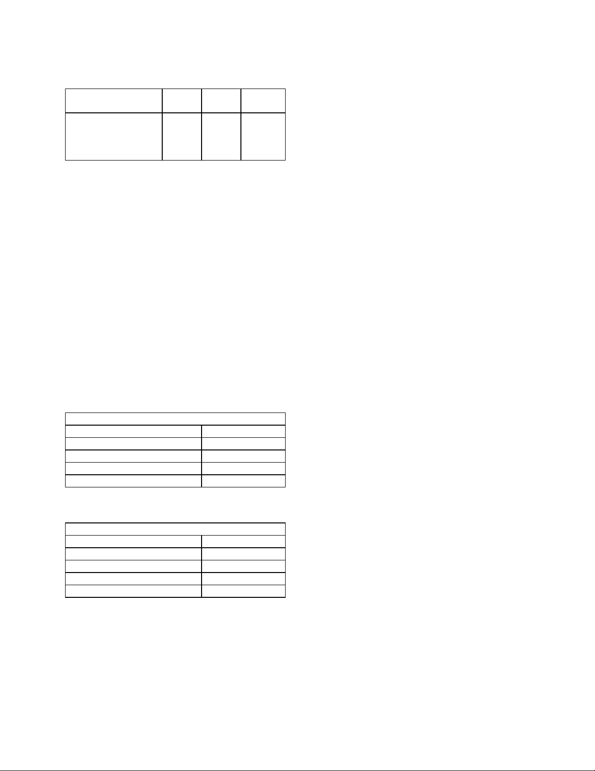
Table 1
Location
Quiet 70' 140' 9,800
Moderate 50' 100' 5,000
Noisy 30' 60' 1,800
Very Noisy 20' 40' 800
Side/
Side
Front/
Back
Square
Feet
INSTALLATION
Connections
Four conductor wire is required for the V -1050C.
Standard 22 or 24 gauge station or JKT is acceptable.
Shielded wire is not required or recommended.
Connections are as follows:
Green Tip
Red Ring
Black Ground
White -24VDC
Tip and Ring are from the page control unit; -24VDC
and ground are from the power supply.
The specifications in Tables 2 and 3 must be met
when wiring this speaker assembly.
Table 2
Maximum Number of Horns per Audio Run
Wire Run in Feet (22 AWG) # of Horns
200 150
400 100
800 50
1600 25
Table 3
Maximum Number of Horns per Power Run
Wire Run in Feet (22 AWG) # of Horns
200 4
400 2
800 1
1600 0
Mounting
The V -1050C should be mounted 12' to 25' high to
obtain optimum results and may be used for either
interior or exterior applications.
• Loosen the wing nut to remove both speakers
from the mounting bracket. Position the
mounting bracket as desired and then re-attach
speakers to the bracket.
Both horns of the V -1050C may be rotated or moved
up and down to obtain the desired position by
loosening the position adjustment knob at the bottom
of each horn approximately one turn, locating the
desired angle placement and re-tighten the knob.
Connection to an electrical box is accomplished by
channeling the wire through the hole in the base.
Holes are punched in the plate for mounting to a
double-gang square box, single-gang or octagon box.
TECHNICAL ASSISTANCE
When trouble is reported, verify there are no broken
connections between the telephone and the ringer.
Ascertain volume control is turned up.
Assistance in troubleshooting is available from the
factory. When calling, you should have a VOM and a
test set available and be calling from the job site. Call
(540) 563-2000 and ask for Technical Support, or call
(540) 767-1555 for Valcom 24-hour Faxback System or
visit our Website at http://www.valcom.com.
Valcom equipment is not field repairable. Valcom, Inc.
maintains service facilities in Roanoke, VA. Should
repairs be necessary, attach a tag to the unit clearly
stating company name, address, phone number,
contact person and the nature of the problem.
Send the unit to:
Valcom, Inc.
Repair and Return Dept
5614 Hollins Road
Roanoke, VA 24019-5056
2
Page 3

Troubleshooting Chart
Symptom Solution
No Output A. Verify -24VDC on the white lead with ground (+) on the black.
B. Verify audio is present on the green and red leads (Monitor with a lineman's
test set at the speaker).
C. Verify volume control turned up (Clockwise).
VALCOM LIMITED WARRANTY
Valcom, Inc. warrants its products to be free from defects in materials and workmanship under conditions of normal use and service
for a period of one year from the date of shipment. The obligation under this warranty shall be limited to the replacement, repair or
refund of any such defective device within the warranty period, provided that:
1. inspection by Valcom, Inc. indicates the validity of the claim;
2. the defect is not the result of damage, misuse, or negligence after the original shipment;
3. the product has not been altered in any way or repaired by others and that factory sealed units are unopened (A service
4. freight charges for the return of products to Valcom are prepaid;
5. all units ‘out of warranty’ are subject to a service charge. The service charge will cover minor repairs (Major repairs will be
This warranty is in lieu of and excludes all other warranties, expressed or implied, and in no event shall Valcom, Inc. be liable
for any anticipated profits, consequential damages, loss of time or other losses incurred by the buyer in connection with the
purchase, operation or use of the product.
This warranty specifically excludes damage incurred in shipment. In the event a product is received in damaged condition, the
carrier sh ould be notified immediately. Claims for such damage should be filed with the carrier involved in accordance with the
F.O.B. point.
Headquarters: In Canada
Valcom, Inc. CMX Corporation
5614 Hollins Road 35 Van Kirk Drive #11 and 12
Roanoke, VA 24019-5056 Brampton, Ontario L7A1A5
Phone: (540) 563-2000 Phone: (905) 456-1072
FAX: (540) 362-9800 FAX: (905) 456-2269
charge plus parts and labor will be applied to units defaced or physically damaged);
subject to additional charges for parts and labor).
3
 Loading...