

Page 1
TECHNICAL ASSISTANCE
When trouble is reported, verify there are no broken connections to the unit.
Assistance in troubleshoting is available from the factory. When calling, you
should have a VOM and a lineman's test set available and be calling from the job
site. Call (540) 563-2000 and ask for Technical Support, or call (540) 767-1555 for
Valcom 24-hour Faxback System or visit our website at http://www.valcom.com.
Valcom equipment is not field repairable. Valcom, Inc. maintains service facilities in
Roanoke, VA. Should repairs be necessary, attach a tag to the unit clearly stating
your company name, address, phone number, contact person, and the nature of the
problem. Send the unit to: Valcom, Inc.
Repair and Return Dept.
5614 Hollins Road
Roanoke, VA 24019-5056
VALCOM LIMITED WARRANTY
Valcom, Inc. warrants its products to be free from defects in materials and
workmanship under conditions of normal use and service for a period of one year from
the date of shipment. The obligation under this warranty shall be limited to the
replacement, repair or refund of any such defective device within the warranty period,
provided that:
1. inspection by Valcom, Inc. indicates the validity of the claim,
2. the defect is not the result of damage, misuse, or negligence after the original
shipment,
3. the product has not been altered in any way or repaired by others and that
factory sealed units are unopened (A service charge plus parts and labor will
be applied to units defaced or physically damaged),
4. freight charges for the return of products to Valcom are prepaid,
5. all units ‘out of warranty’ are subject to a service charge. The service charge
will cover minor repairs (Major repairs will be subject to additional charges for
parts and labor).
This warranty is in lieu of and excludes all other warranties, expressed or
implied, and in no event shall Valcom, Inc. be liable for any anticipated profits,
consequential damages, loss of time or other losses incurred by the buyer
in connection with the purchase, operation, or use of the product.
This warranty specifically excludes damage incurred in shipment. In the event a
product is received in damaged condition, the carrier should be notified immediately.
Claims for such damage should be filed with the carrier involved in accordance with the
F.O.B. point.
Headquarters: In Canada
Valcom, Inc. CMX Corporation
5614 Hollins Road 35 Van Kirk Drive #11 and 12
Roanoke, VA 24019-5056 Brampton, Ontario L7A1A5
Phone: (540) 563-2000 Phone: (905) 456-1072
FAX: (540) 362-9800 FAX: (905) 456-2269
INSTALLATION INSTRUCTIONS FOR
SLIMLINE WALL™ AMPLIFIED WALL SPEAKERS
MODEL NO. V-1042
Issue 6 947044
Page 2
VALCOM ONE -WAY AMPLIFIED SLIMLINE™ WALL SPEAKER
18 to
WALL MOUNTING
HANGER
Valcom Slimline Wall Speaker, V -1042, is self-amplified and may be used to provide
one-way paging from any Valcom one-way or talkback page control. This speaker
has an externally accessible volume control located behind the grille and is
screwdriver adjustable. The V -1042 will cover an area up to 600 square feet and
should be spaced 20 feet apart. Good quality paging will be heard up to 30 feet in
front of the speaker. The V -1042 requires -24VDC, 50mA (1 Valcom power unit).
The speaker is available in black, white, brown and gray with a color coordinated
cloth grille. Custom colors are available upon request.
Model V -1042-BK Black
Model V -1042-W White
Model V -1042-BR Brown
Model V -1042-GY Gray
US Patent Number D357,682, UK Registered 2041547
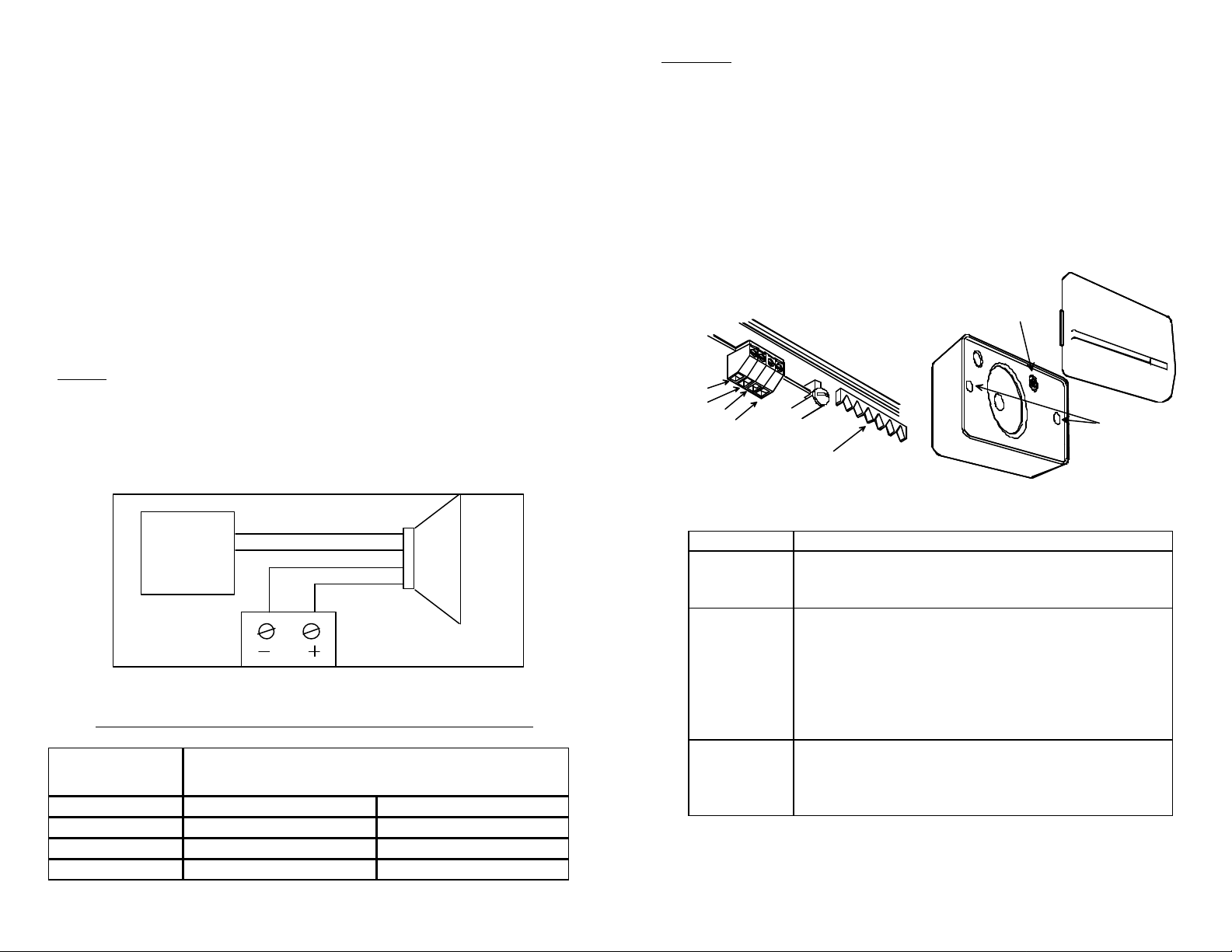
Wiring
Make connections as shown in Figure 1. Insert stripped wire (approximately 3/16")
into appropriate terminal (See Figure 2) and clamp the wire by turning the screw.
Each connector accepts 18 to 24 AWG wire.
Note: Do not connect this speaker directly to a 25/70/100 Volt amplifier as
damage to both the amplifier and speaker may occur.
Valcom Page
Control
FIGURE 1
Page
Out
Tip/A
Ring/B
-24VDC
GND
Valcom -24VDC
Power Supply
One-Way
Amplified
Speaker
Recommended Quantity of Speakers per Specific Power Run
Speakers per
Power Run
V-1042 24 AWG 22 AWG
15 250 400
7 500 800
3 1000 1600
Wire Run Length (Feet)
Mounting
The baffle provides two methods of mounting:
1. The baffle can be suspended from a nail or hook by a "hanger" that is
attached to the housing. See Figure 2.
2. The unit can be attached to a wall using two mounting bosses. Distance
between the mounting boss holes’ center is 8.5". Remove gr ille and
secure baffle to wall with screws. This mounting provides better low
frequency response for music and a more secure attachment to the wall.
See Figure 3.
FIGURE 2
RING/B
TIP/A
-24VDC
GROUND
FIGURE 3
TROUBLESHOOTING CHART
SYMPTOM ACTION
No audio from
speaker
Low volume
from speaker
Loud squeal
(feedback)
1. Verify volume control is turned up (clockwise).
2. Using a lineman's test set, check for proper audio level on
Tip/A and Ring/B leads and if necessary at the source.
1. Verify volume control is turned up.
2. Check voltage at the speaker when in use (-
-24VDC required).
3. Using a lineman's test set, check for proper audio level on
Tip/A and Ring/B leads. It is possible some low level
audio will be heard with only one side of Tip/A and
Ring/B connected.
1. Decrease volume of speaker (counterclockwise).
2. Increase the distance between telephone and speaker.
3. Install confidencer on the telephone in severe problem
areas.
Dimensions/Weight
• 7.00" H x 10.30" W x 3.40" D (17.78cm H x 26.16cm W x 8.64cm D)
• 2.8 lbs. (1.27 kg)
VOLUME CONTROL
BOSSES
 Loading...