

Page 1
Issue 0
A
V-1040
INSTALLATION INSTRUCTIONS FOR
CLEAN ROOM CEILING SPEAKER
The Valcom Ceiling Speaker, V-1040 is a self-amplified and capable of reproducing voice paging in clean room
environments. The V-1040 has a screwdriver adjustable volume control located on the 1 watt amplifier circuit
board. The V-1040 has an 8-inch speaker. The speaker requires -24VDC, 50mA (1-power unit). The speaker
features the following, large rubber o-ring to seal the grille to the ceiling, rubber washers for all mounting hardware
and a polycarbonate dust shield located between the speaker and the grille.
Dimensions/Weight
• V-1040 13.00"Dia. x 3.00"D (33.02cm Dia. x 7.62cm D) 2.5 lbs. (1.13kg)
Coverage
The area covered by a ceiling speaker is determined by the height of the ceiling. If ceiling height is 8 feet,
the speaker will cover 256 sq. ft. With a ceiling height of 10 feet, the speaker will cover 400 sq. ft. If the
ceiling is 20 feet high, the speaker will cover 1600 sq. ft.
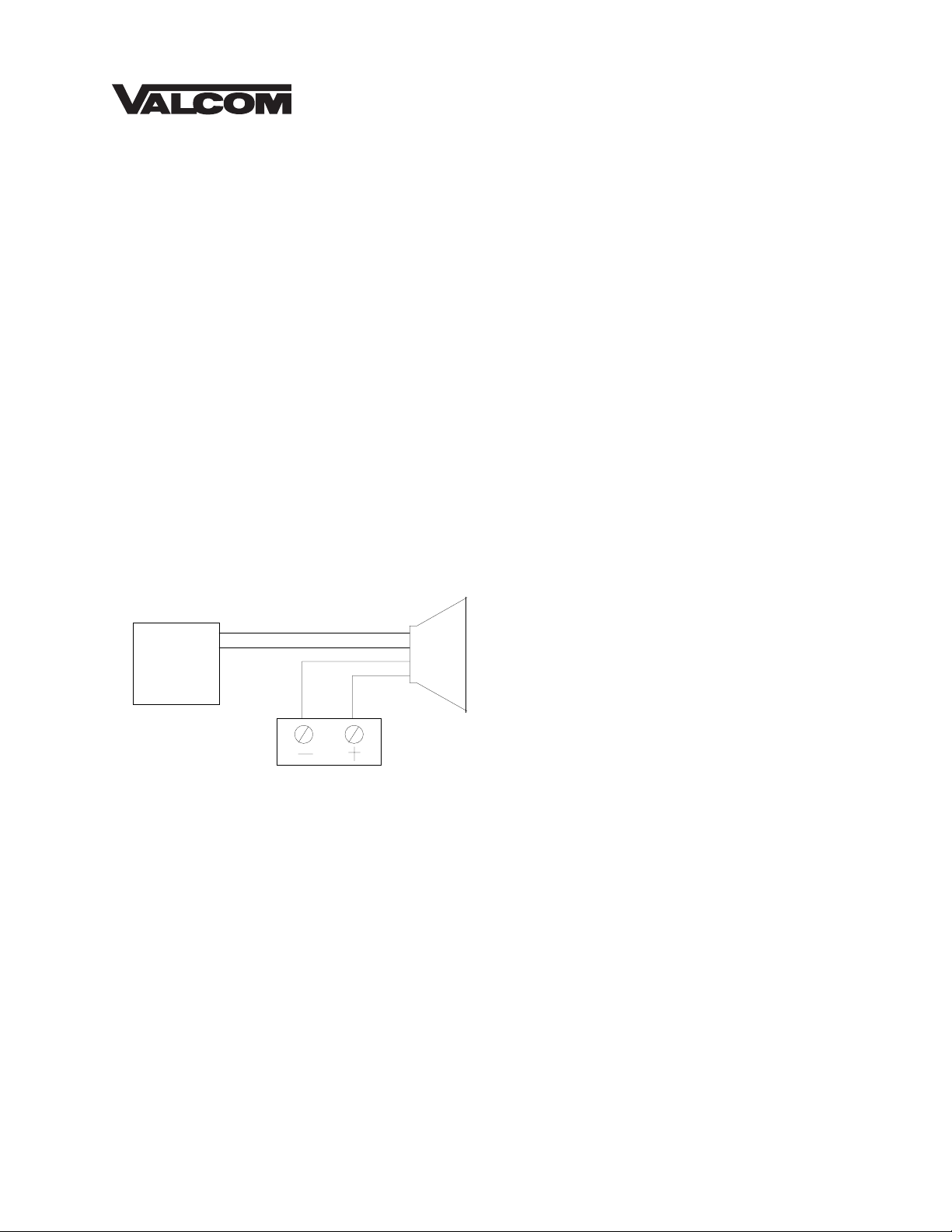
Connections
Refer to Figure 1 for audio and electrical
connections. Category 3 24 AWG structured
Page
Out
Valcom Page
Control
FIGURE 1: TYPICAL CONNECTIONS
(Tip/A)
(Ring/B)
(-24Vdc)
(Gnd)
One-Way
mplified
Speaker
Valcom -24 Vdc
Power Supply
cable may be used for all connections.
NOTE: Do not connect this speaker directly
to a 25/70/100 Volt amplifier as damage to
both the amplifier and speaker may occur.
A V-1095 may be used to allow the use of
Valcom self-amplified speakers on 70V
speaker lines.
Installation
Suspended Ceiling Installation
After determining the speaker location and referring to Figure 2 cut an 8.5” diameter hole in the ceiling
tile. Attach the backbox to the bridge with the four screws provided and position the assembly on the
back of the ceiling tile. Before continuing speaker installation using a small screwdriver set Volume
Control to 2/3 rotation. Place the large rubber O-ring on the back of the speaker assembly and using
the four screws equipped with washers and O-rings mount the speaker assembly to the bridge/backbox
assembly. Do not over-tighten the speaker mounting screws. Hand-tighten only. For a proper seal the
large O-ring should compress slightly. It is not necessary for the edge of the metal grille to touch the
ceiling tile for a proper seal. Refer to Figure 2.
1 947994
Page 2
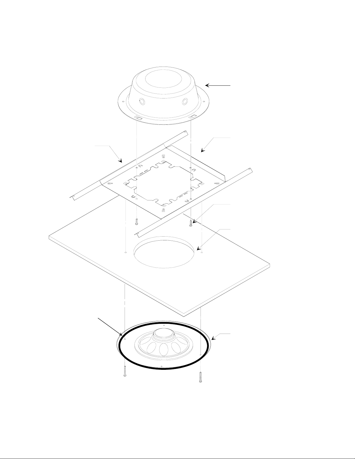
FIGURE 2: V-1040 INSTALLATION INSTRUCTIONS
V-9915M-5 Backbox
V-9914M-5 Bridge
Bend tabs down to
locate bridge in
ceiling tile cutout
Large Rubber
O-Ring Placement
Attach backbox to
bridge with 4 screws
provided
Cut 8.5" round
hole in ceiling tile
Ceiling Grille
and 8" Speaker
Assembly
(4 white screws
with rubber washers
provided)
2
Page 3

Solid Surface Ceiling (Sheetrock)
In a sheetrock ceiling installation it is necessary to install the preconstruction ring and backbox assembly
before the installation of the sheetrock. Referring to Figure 3 mount the backbox to the speaker mounting
ring and attach the assembly to the ceiling joists using the appropriate hardware. Cut a 12 1/8” diameter
hole in the in the sheetrock to provide clearance for the speaker mounting ring and backbox assembly.
Before continuing speaker installation using a small screwdriver set Volume Control to 2/3
rotation. Place the large rubber O-ring on the back of the speaker assembly and using the four screws
equipped with washers and O-rings mount the speaker assembly to the speaker ring/backbox assembly.
Do not over-tighten the speaker mounting screws. Hand-tighten only. For a proper seal the large O-ring
should compress slightly. It is not necessary for the edge of the metal grille to touch the ceiling for a
proper seal. Refer to Figure 3.
3
Page 4

TECHNICAL ASSISTANCE
When trouble is reported, verify there are no broken
connections. Assistance in troubleshooting is
available from the factory. Call (540) 563-2000 and
press “1” for Technical Support, or visit our website
at http://www.valcom.com.
Valcom equipment is not field repairable. Valcom,
Inc. maintains service facilities in Roanoke, VA.
Should repairs be necessary, attach a tag to the unit
clearly stating company name, address, phone
number, contact person and nature of the problem.
Send the unit to:
Valcom, Inc.
Repair & Return Dept.
5614 Hollins Road
Roanoke, VA 24019-5056
TROUBLESHOOTING CHART
SYMPTOMS ACTIONS
1. No audio from speaker 1a. Check that volume control is turned up (Clockwise).
1b. Using a lineman's test set, check for the proper audio level on the Tip and Ring
leads and if necessary also at the source.
2. Low volume from speaker 2a. Check that volume control is turned up.
2b. Check voltage at the speaker assembly when in use, -18 to -24VDC required.
2c. Using a lineman's test set, check for the proper audio level on Tip and Ring leads.
It is possible that some low-level audio will be heard with only one side of Tip
and Ring connected.
3. Loud squeal (Feedback) 3a. Turn down (Counter-clockwise) volume of the speaker.
3b. Increase the distance between the telephone and speaker.
3c. Install a noise canceling handset on the telephone in severe problem areas.
3d. Add a V-9962, Digital Feedback Eliminator.
VALCOM LIMITED WARRANTY
Valcom, Inc. warrants its products to be free from defects in materials and workmanship under conditions of normal use and service
for a period of one year from the date of shipment. The obligation under this warranty shall be limited to the replacement, repair or
refund of any such defective device within the warranty period, provided that:
1. inspection by Valcom, Inc. indicates the validity of the claim;
2. the defect is not the result of damage, misuse or negligence after the original shipment;
3. the product has not been altered in any way or repaired by others and that factory sealed units are unopened (A service
4. freight charges for the return of products to Valcom are prepaid;
5. all units ‘out of warranty’ are subject to a service charge. The service charge will cover minor repairs (Major repairs will
This warranty is in lieu of and excludes all other warranties, expressed or implied, and in no event shall Valcom, Inc. be
liable for any anticipated profits, consequential damages, loss of time or other losses incurred by the buyer in connection
with the purchase, operation or use of the product.
This warranty specifically excludes damage incurred in shipment. In the event a product is received in damaged condition, the
carrier should be notified immediately. Claims for such damage should be filed with the carrier involved in accordance with the
F.O.B. point.
Headquarters: In Canada
Valcom, Inc. CMX Corporation
5614 Hollins Road 35 Van Kirk Drive #11 and 12
Roanoke, VA 24019-5056 Brampton, Ontario L7A 1A5
Phone: (540) 563-2000 Phone: (905) 456-1072
FAX: (540) 362-9800 FAX: (905) 456-2269
charge plus parts and labor will be applied to units defaced or physically damaged);
be subject to additional charges for parts and labor).
4
 Loading...