

Page 1
VSP-V-1030C/1036C
Issue 8
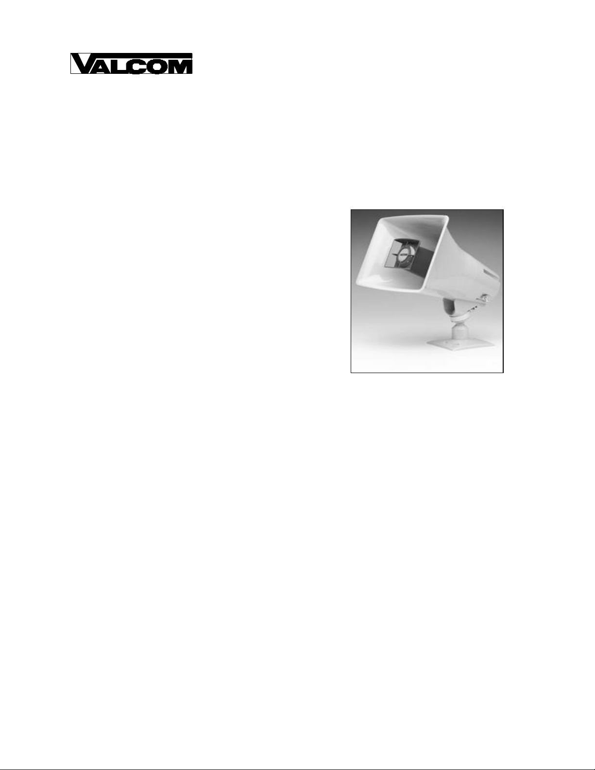
V-1030C and V-1036C
PAGING HORN AMPLIFIER ASSEMBLIES
INTRODUCTION
This instruction contains the specifications and
information necessary to install, operate, and maintain
the V -1030C and the V-1036C Paging Horn Amplifier
Assemblies.
This equipment has received FCC type KX
registration, designed to be used with FCC registered
Key Telephone Systems. In accordance with FCC
Rules with applicable tariffs, this Paging Unit may
only be installed with the authorization of the host
system. Installations may be made by Valcom, Inc.,
an authorized agent of the same, equipment
manufacturers, telephone companies, registered
telephone refurbishers, and those qualified for
installation of FCC registered systems under FCC
Rules Section 68.215.
The FCC Registration Number,
BAFUSA-69358-KX-N, will be listed in the affidavits
filed with the Telephone Company; it will also be
recorded in the system log kept by installation and
maintenance personnel. The local Telephone
Company is to be notified of the FCC Registration
Number when this Paging Unit is installed.
SPECIFICATIONS
Description
The V -1030C and V-1036C are Paging Horn/ Amplifier
Assemblies. The V -1030C is a self- contained 5 Watt
paging system with a 5 Watt amplifier; the V -1036C is
a self-contained 15 Watt paging system with a 15
Watt amplifier. Both units incorporate a high
efficiency horn with a volume control.
Applications
• Use with Valcom page control
• Expanding the capability of telephone systems
which contain limited paging capabilities
• Loud ringer application in systems where
loud-speaker tone signaling is employed
1 947031
V-1030C - Nominal Specifications
Input Impedance: 1000 Ohms nominal
Input level: -15dBm to +10dBm
Current at -24VDC: 300mA
V-1036C - Nominal Specifications
Input Impedance: 1000 Ohms nominal
Input level: -15dBm to +10dBm
Current at -24VDC: 900mA
Dimensions/Weights
• V-1030C - 7.38" H x 10.00" W x 10.40" D
(18.75cm H x 25.40cm W x 26.42cm D)
• 3.6 lbs. (1.63 kg)
• V-1036C - 7.38" H x 10.00" W x 10.40" D
(18.75cm H x 25.40cm W x 26.42cm D)
• 3.7 lbs. (1.68 kg)
Environment
• Temperature: -20 to +55 Degrees C
• Humidity: 0 - 95% non-precipitating
Page 2
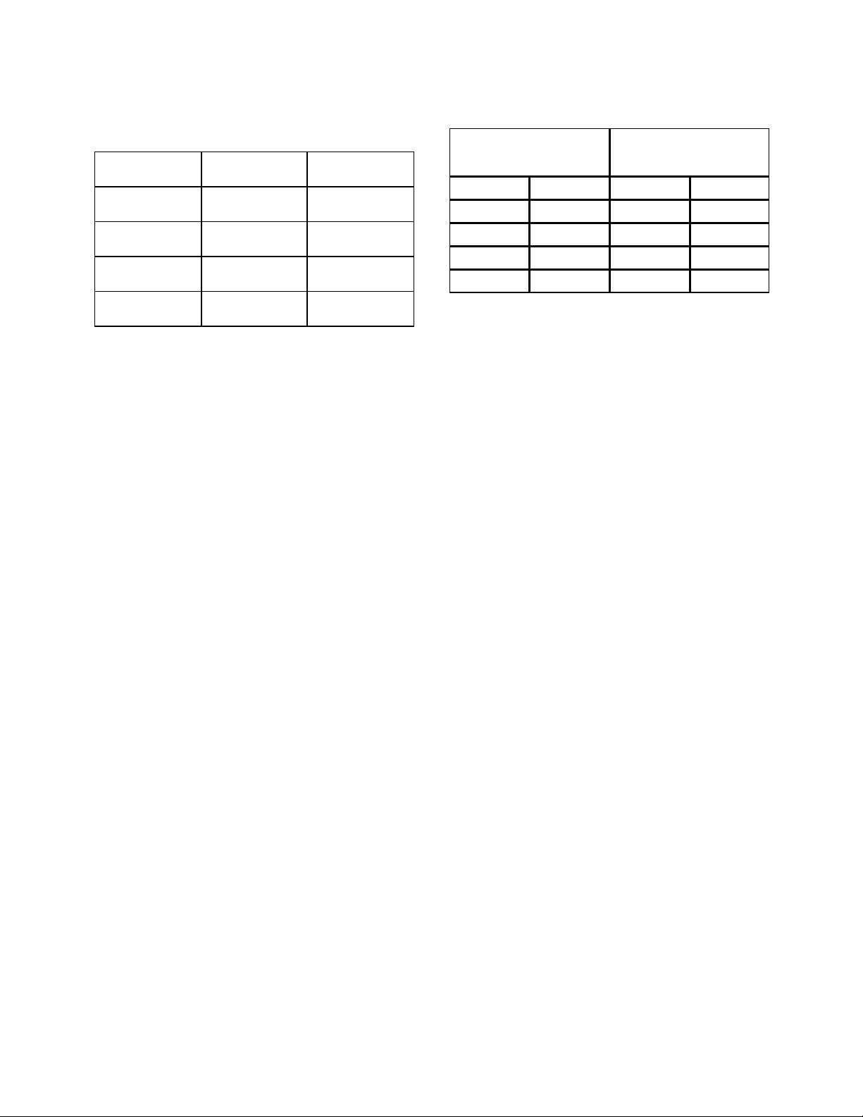
Horn Spacing
(Coverage shown in parenthesis)
Location V-1030C
5 Watt
Quiet 110'
(12,000 sq. ft.)
Moderate 80'
(6,400 sq. ft.)
Noisy 50'
(2,500 sq. ft.)
Very Noisy 30'
(900 sq. ft.)
V-1036C
15 Watt
N/A
N/A
75'
(5,600 sq. ft.)
45'
(2,000 sq. ft.)
Example: In a quiet environment, V -1030C, 5 Watt
Horns, would be spaced 110 feet apart side to side
and would provide good quality sound 110 feet in
front of each horn approximately 12,000 sq. ft. of
coverage.
Definitions:
Quiet: 50-65db. This would include areas such as
waiting rooms, doctor’s examination rooms, stock
areas, etc.
Moderate: 65-80db. This includes areas such as
warehouses, shipping areas or light manufacturing.
Noisy: 80-90db. This includes machine shops or
heavy manufacturing.
Very Noisy: Greater than 90db. This would include
any areas where talking to another person is very
difficult. Workers may be required to wear ear plugs.
Audio Wire Runs
When a remote power unit is used, the audio pair run
should be limited to 5,000 feet and a maximum of 4
horns when using 24 AWG wire. A V -1094A, Page
Port Pre-Amp/Expander, may be added to increase the
number of horns and/or distance. Twisted pair wire
(standard telephone wire) should be used for
connections.
Power Wire Run
For good quality sound, the distance recommended
between the power supply and horns should be
adhered to.
See the Valcom power run gauge guide for additional
wire gauges and distances.
Number of Horns
per Power Run
15 Watt 5 Watt
V-1036C V-1030C 24 AWG 22AWG
1 4 125 200
0 2 250 400
0 1 500 800
Wire Run Length
(Feet)
INSTALLATION
Wiring Connections
Twisted pair wire (standard telephone wire) shoul d be
used for connections.
Green - Tip (Audio)
Red - Ring (Audio)
Black - Ground Power In
White - (-24VDC)
Brown - Not Used
Attaching Speaker to Base
NOTE: For ease of installation, the base can be
attached to the speaker bef ore or after the base is
mounted.
• Loosen position adjustment knob
• Insert the ball of the base into the socket of the
speaker
• Tighten the position adjustment knob
Mounting
These horns should be mounted 15 to 20 feet above
the floor to allow for best sound distribution. The
units can be mounted to a wall, a beam or an electrical
box.
• Mount the base to a wall using the two holes
provided. Knockout holes are provided for
punch out should additional holes be desired.
• A "C" clamp is provided with the horns to allow
mounting to a beam. Place the bolt through the
hole in the bottom of the base to secure the "C"
clamp to the beam (See Figure 1). It is suggested
that the horn be mounted to the underside of the
"I" beam to provide maximum positioning
adjustments.
2
Page 3

• Connection to an electrical backbox is
accomplished by channeling wire through the
ball of the base and making appropriate
connections. The base has holes punched for a
double-gang square box, but by punching out
additional knockout holes, the base can be
mounted to a single-gang or octagon box (See
Figure 2).
The horns may be rotated or moved up and down to
obtain the desired position by loosening the position
adjustment knob (See Figures 1 and 2) at the bottom
of the unit approximately one turn. Make required
adjustments and re-tighten knob.
TECHNICAL ASSISTANCE
When trouble is reported, verify the unit is properly
connected and there are no broken connections
leading to this unit. Ascertain volume control is
turned up.
Assistance in troubleshooting is available from the
factory. When calling, you should have a VOM and a
test set and call from the job site. Call (540) 563-2000
and ask for Technical Support, or call (540) 767-1555
for Valcom 24-hour Faxback System or visit our
website at http://www.valcom.com.
Valcom equipment is not field repairable. Valcom, Inc.
maintains service facilities in Roanoke, VA. Should
repairs be necessary, attach a tag to the unit clearly
stating company name, address, phone number,
contact person, and the nature of the problem. Send
the unit to:
Repair and Return Dept.
Valcom, Inc.
5614 Hollins Road
Roanoke, VA 24019-5056
TROUBLESHOOTING CHART
PROBLEMS PROBABLE CAUSES AND CORRECTIONS
No Sound • Check that volume control is turned up (clockwise).
• Check prese nce and polarity of -24VDC and GND.
• Using a telephone test set, check for the proper audio level on the Tip
and Ring leads, and if necessary also at the source.
Low Volume • Check that volume control is turned up (clockwise).
• Check voltage at the horn when in use, -18 to -24VDC required.
• Using a telephone test set, check for proper audio level on Tip and Ring
leads. It is possible that some low level audio will be heard with only one
side of Tip and Ring connected.
Loud Squeal • Lower volume of horn.
• Aim hor n in different direction.
• Increase the distance between the telephone and horn.
• Install a confidencer on the telephone in severe problem areas.
3
Page 4

I-Beam
Figure 2 - Mounting to an Electrical Backbox
VALCOM LIMITED WARRANTY
Valcom, Inc. warrants its products to be free from defects in materials and workmanship under conditions of normal use and service
for a period of one year from the date of shipment. The obligation under this warranty shall be limited to the replacement, repair or
refund of any such defective device within the warranty period, provided that:
1. inspection by Valcom, Inc. indicates the validity of the claim,
2. the defect is not the result of damage, misuse, or negligence after the original shipment,
3. the product has not been altered in any way or repaired by others and that factory sealed units are unopened (A service
4. freight charges for the return of products to Valcom are prepaid,
5. all units ‘out of warranty’ are subject to a service charge. The service charge will cover minor repairs (Major repairs will be
This warranty is in lieu of and excludes all other warranties, expressed or implied, and in no event shall Valcom, Inc. be liable
for any anticipated profits, consequential damages, loss of time or other losses incurred by the buyer in connection with the
purchase, operation, or use of the product.
This warranty specifically excludes damage incurred in shipment. In the event a product is received in damaged condition, the
carrier should be notified immediately. Claims for such damage should be filed with the carrier involved in accordance with the
F.O.B. point.
Headquarters: In Canada
Valcom, Inc. CMX Corporation
5614 Hollins Road 35 Van Kirk Drive #11 and 12
Roanoke, VA 24019-5056 Brampton, Ontario L7A1A5
Phone: (540) 563-2000 Phone: (905) 456-1072
FAX: (540) 362-9800 FAX: (905) 456-2269
charge plus parts and labor will be applied to units defaced or physically damaged),
subject to additional charges for parts and labor).
"C" Clamp
Speaker Base
Figure 1 - Mounting to a Beam with a "C" Clamp
Wire
Position
Adjustment
Knob
Speaker
Base
Position
Adjustment
Knob
Electrical
Backbox
4
 Loading...