

Page 1
TECHNICAL ASSISTANCE
When trouble is reported, verify there are no broken connections to the unit.
Assistance in troubleshooting is available from the factory. When calling, you should
have a VOM and a lineman's test set available and be calling from the job site. Call
(540) 427-3900 and ask for Technical Support, or call (540) 427-6000 for Valcom
24-hour Automated Support or visit our website at http://www.valcom.com.
Valcom equipment is not field repairable. Valcom, Inc. maintains service facilities in
Roanoke, VA. Should repairs be necessary, attach a tag to the unit clearly stating
your company name, address, phone number, contact person, and the nature of the
problem. Send the unit to:
Valcom, Inc.
Repair and Return Dept.
5614 Hollins Road
Roanoke, VA 24019-5056
VALCOM LIMITED WARRANTY
Valcom, Inc. warrants its products to be free from defects in materials and workmanship
under conditions of normal use and service for a period of one year from the date of
shipment. The obligation under this warranty shall be limited to the replacement, repair
or refund of any such defective device within the warranty period, provided that:
1. inspection by Valcom, Inc. indicates the validity of the claim,
2. the defect is not the result of damage, misuse, or negligence after the original
shipment,
3. the product has not been altered in any way or repaired by others and that factory
sealed units are unopened (A service charge plus parts and labor will be applied to
units defaced or physically damaged),
4. freight charges for the return of products to Valcom are prepaid,
5. all units 'out of warranty' are subject to a service charge. The service charge will
cover minor repairs (Major repairs will be subject to additional charges for parts and
labor).
INSTALLATION INSTRUCTIONS FOR
AMPLIFIED TRACK STYLE SPEAKERS
This warranty is in lieu of and excludes all other warranties, expressed or implied,
and in no event shall Valcom, Inc. be liable for any anticipated profit s, consequential
damages, loss of time or other losses incurred by the buyer in connection with the
purchase, operation or use of the product.
This warranty specifically excludes damage incurred in shipment. In the event a product
is received in damaged condition, the carrier should be notified immediately. Claims for
such damage should be filed with the carrier involved in accordance with the F.O.B.
point.
Headquarters:
Valcom, Inc.
1111 Industry Avenue
Roanoke, VA 24013
Phone: (540) 427-3900
FAX: (540) 427-3517
35 Van Kirk Drive #11 and 12
Brampton, Ontario L7A1A5
In Canada:
CMX Corporation
Phone: (905) 456-1072
FAX: (905) 456-2269
MODEL NO. V-1013A AND V-1014A
Issue 4 947034
Page 2
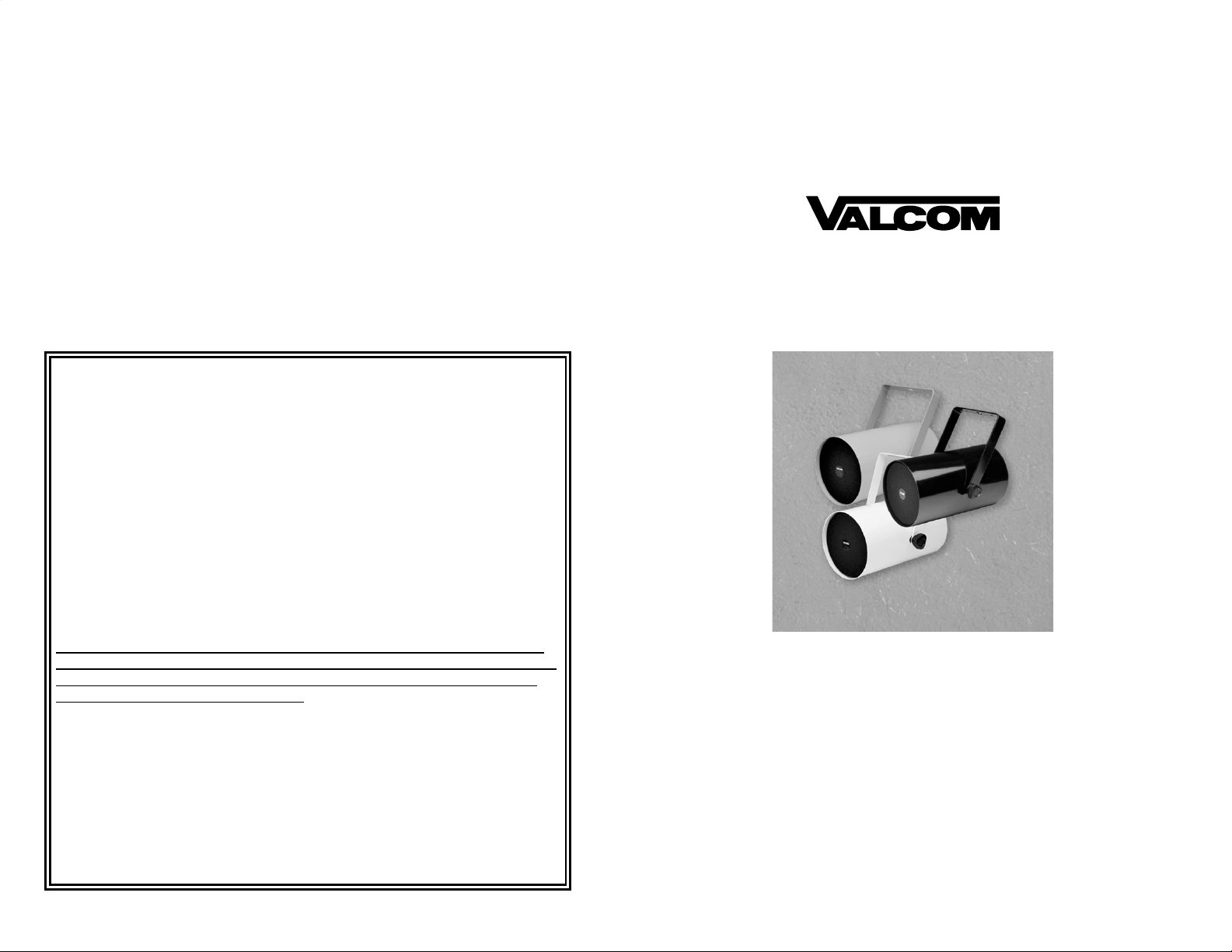
VALCOM ONE-WAY AMPLIFIED TRACK STYLE SPEAKERS
Valcom Track Style Speakers, V-1013A (one-watt) and V-1014A (five watt), are
weather resistant, self-amplified and provide voice paging as well as background
music. These speakers have externally accessible volume controls that are adjustable
by a screwdriver through the hole in the grille and are availab l e in white, black, and
gray.
Model V-1013A-W White Model V-1014A-W
Model V-1013A-BK Black Model V-1014A-BK
Model V-1013A-GY Gray Model V-1014A-GY
DIMENSIONS/WEIGHT
• V-1013A- 5.8”Dia x 10”H (14.73cm Dia. x 25.4cm H)
• 2.5 lbs. (1.14kg)
• V-1014A- 5.8”Dia x 10”H (14.73cm Dia. x 25.4cm H)
• 3.1 lbs. (1.41kg)
Typical coverage of these speakers is 600 square feet with good quality paging
heard up to thirty feet in front of the speaker. Speakers should be spaced
approximately twenty feet apart. The five watt version is recommended for
higher noise level areas.
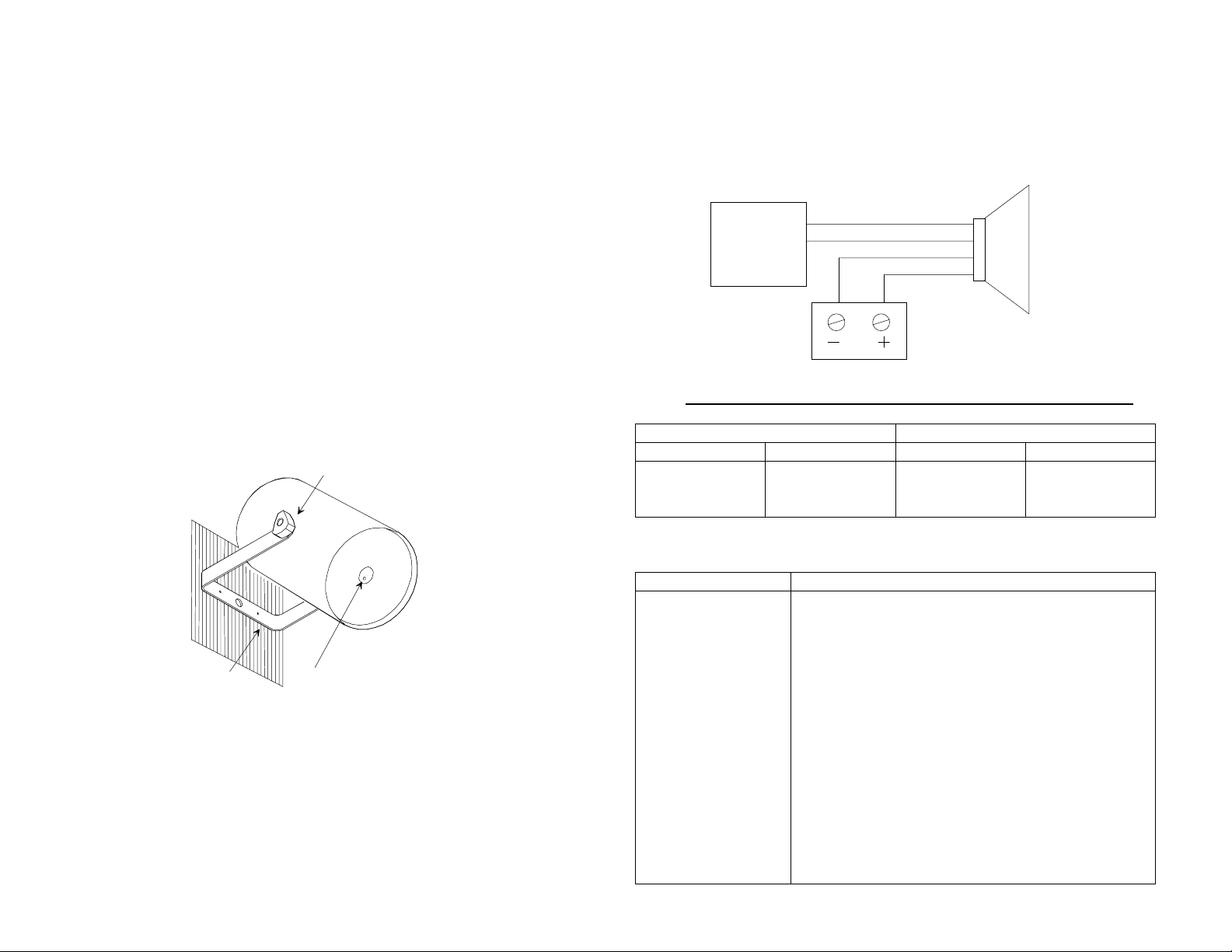
CONNECTIONS
Valcom Page
FIGURE 2
Control
Page
Out
(Tip/A) Green
(Ring/B) Red
(-24VDC) White
(GND) Black
Valcom -24VDC
Power Supply
One-Way
Amplified
Speaker
The V-1013A requires -24VDC, 50 mA (1 Valcom Power Unit) and the
V-1014A requires -24VDC, 300 mA (6 Power Units).
The V-1013A and V-1014A are both FCC Part 68 Registered under
BAFUSA-69358-KX-N.
Mounting
Bracket
Knob
Volume
Control
FIGURE 1
Note: Do not connect this speaker directly to a 25/70/100 volt amplifier
as damage to both the amplifier and speaker may occur.
INSTALLATION
1. Mount the bracket.
2. Remove knobs and mount speaker to bracket.
3. Attach knobs and position at the desired angle. Tighten knobs. (See Figure 1).
Recommended Quantity of Speakers per Specific Power Run
Speakers per Power Run Wire Run Length (Ft.)
V-1013A V-1014A 24AWG 22AWG
15
7
3
2
1
0
250
500
1000
TROUBLESHOOTING CHART
SYMPTOM ACTION
No audio from
speaker
1. Verify volume control is turned up (clockwise).
2. Using a lineman's test set, check for proper audio
level at Tip and Ring leads and if necessary at the
source.
Low volume from
speaker
1. Verify volume control is turned up.
2. Check voltage at the speaker when in use, (-18 to
-24VDC required).
3. Using a lineman's test set, check for proper audio
level on Tip and Ring leads. It is possible that
some low level audio will be heard with only one
side of Tip and Ring connected.
Loud squeal
(feedback)
1. Decrease volume of speaker (counterclockwise).
2. Increase the distance between telephone and
speaker.
3. Install confidencer on the telephone in severe
problem areas.
400
800
1600
Page 3

 Loading...