

Page 1
VSP-1010C/1020C/1020KNOB/1021C
INSTALLATION INSTRUCTIONS FOR
AMPLIFIED CEILING SPEAKERS
Issue 6
V-1010C
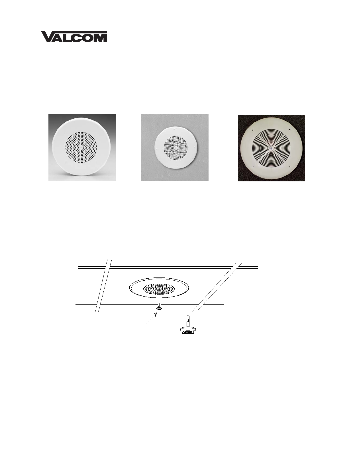
Valcom Ceiling Speakers, V-1010C, V-1020C, V-1020KNOB and V-1021C are self-amplified and are
capable of reproducing voice paging as well as background music. The V-1020KNOB has a permanent
knob for volume adjustments, the V-1010C and V-1020C feature a removable volume control knob and the
V-1021C has an externally accessible volume control that can be adjusted by screwdriver through the center
hole on the grille. The V-1010C is a 4-inch speaker and the others are 8-inch speakers. All speakers
require -24VDC, 50mA (1-power unit) and are FCC Part 68 registered under BAFUSA-69358-KX-N.
Volume Control
V-1020C/V-1020KNOB
(Knob included with V-1010C and V-1020C)
V-1021C
Dimensions/Weight
• V-1010C 7.65"Dia. x 2.90"D (19.43cm Dia. x 7.37cm D) 1.7 lbs. (0.77kg)
• V-1020C/1020KNOB 13.00"Dia. x 3.00"D (33.02cm Dia. x 7.62cm D) 2.5 lbs. (1.13kg)
• V-1021C 11.00"Dia. x 3.00"D (27.94cm Dia x 7.62cm D) 1.5 lbs. (0.68kg)
1 947295
Page 2
Page
A
A
o
T
f
f
w
Out
Valcom Page
Control
(Tip/A)
(Ring/B)
(-24VDC)
(Gnd)
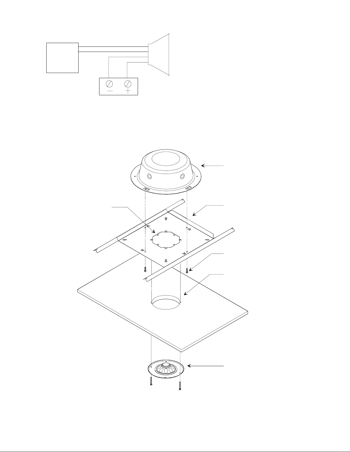
FIGURE 1: TYPICAL CONNECTIONS
FIGURE 2: V-1010C INSTALLATION INSTRUCTIONS
One-Way
mplified
Speaker
Valcom -24VDC
Power Supply
NOTE: Do not connect this speaker directly
to a 25/70/100 Volt amplifier as damage to
both the amplifier and speaker may occur.
A V-1095 may be used to allow the use of
Valcom self-amplified speakers on 70V
speaker lines.
V-9915M-5 Backbox
Bend tabs down to
locate bridge in
ceiling tile
cutout.
he V-9904M-5 is recommended
or use where extra speaker
support is needed. A V-9915M-5
may be added to the V-9904M-5
or backbox protection
NOTE: The V-9915M-5 cannot
be used in V-1010C installations
ithout the V-9904M-5.
V-9904M-5 Bridge
ttach backbox t
bridge us ing 4 screws
provided
Cut 5.25" round
hole in ceiling tile
4" Ceiling Grille
and Speaker
2 947295
Page 3

FIGURE 3: V-1020C AND V-1020KNOB INSTALLATION INSTRUCTIONS
V-9915M-5 Backbox
V-9914M-5 Bridge
Bend tabs down to
locate bridge in
ceiling tile cutout
Attach backbox to
bridge with 4 screws
provided
Cut 8.5" round
hole in ceiling tile
8" Ceiling Grille
and Speaker
(4 white screws
provided)
NOTE:
FOR: V-1020C V-1020KNOB V-1020C
BRIDGE V-9914M-5 V-9914M-5 V-9914
BACKBOX V-9915M-5 V-9915M-5 V-9915
COVERAGE
The area covered by a ceiling speaker is determined by the height of the ceiling. If ceiling height is eight
feet, the speaker will cover 256 sq. ft. With a ceiling height of ten feet, the speaker will cover 400 sq. ft. If
the ceiling is 20 feet high, the speaker will cover 1600 sq. ft.
3 947295
Page 4
TECHNICAL ASSISTANCE
When trouble is reported, verify there are no
broken connections. Assistance in
troubleshooting is available from the factory.
Call (540) 563-2000 and press 1 for Technical
Support or visit our website at
http://www.valcom.com.
Valcom equipment is not field repairable. Valcom,
Inc. maintains service facilities in Roanoke, VA.
Should repairs be necessary, attach a tag to the
unit clearly stating company name, address,
phone number, contact person and nature of the
problem. Send the unit to:
Valcom, Inc.
Repair & Return Dept.
5614 Hollins Road
Roanoke, VA 24019-5056
TROUBLESHOOTING CHART
SYMPTOMS ACTIONS
1. No audio from speaker 1a. Check that volume control is turned up (Clockwise).
1b. Using a lineman's test set, check for the proper audio level on the
Tip and Ring leads and if necessary also at the source.
2. Low volume from speaker 2a. Check that volume control is turned up.
2b. Check voltage at the speaker assembly when in use, -18 to
-24VDC required.
2c. Using a lineman's test set, check for the proper audio level on Tip
and Ring leads. It is possible that some low-level audio will be
heard with only one side of Tip and Ring connected.
3. Loud squeal (Feedback) 3a. Turn down (Counter-clockwise) volume of the speaker.
3b. Increase the distance between the telephone and speaker.
3c. Install a noise canceling handset on the telephone in severe
problem areas.
3d. Add a V-9964, Digital Feedback Eliminator.
Valcom, Inc. warrants its products to be free from defects in materials and workmanship under conditions of normal use and service
VALCOM LIMITED WARRANTY
for a period of one year from the date of shipment. The obligation under this warranty shall be limited to the replacement, repair or
refund of any such defective device within the warranty period, provided that:
1. inspection by Valcom, Inc. indicates the validity of the claim;
2. the defect is not the result of damage, misuse or negligence after the original shipment;
3. the product has not been altered in any way or repaired by others and that factory sealed units are unopened (a service
4. freight charges for the return of products to Valcom are prepaid;
5. all units ‘out of warranty’ are subject to a service charge. The service charge will cover minor repairs (major repairs will
This warranty is in lieu of and excludes all other warranties, expressed or implied, and in no event shall Valcom, Inc. be
liable for any anticipated profits, consequential damages, loss of time or other losses incurred by the buyer in connection
with the purchase, operation or use of the product.
This warranty specifically excludes damage incurred in shipment. In the event a product is received in damaged condition, the
carrier should be notified immediately. Claims for such damage should be filed with the carrier involved in accordance with the
F.O.B. point.
charge plus parts and labor will be applied to units defaced or physically damaged);
be subject to additional charges for parts and labor).
Headquarters:
Valcom, Inc.
5614 Hollins Road
Roanoke, VA 24019-5056
Phone: (540) 563-2000
FAX: (540) 362-9800
4 947295
 Loading...