

Page 1

®
PagePac
by
PAGEPAC PLUS ZONE EXPANSION UNIT
V-5335100
INTRODUCTION
The Zone Expansion Unit (ZEU) provides up to
16 zones of audio output (including talkback),
contact closure outputs or inputs.
Issue 3
SPECIFICATIONS (see Table 2)
FEATURES
• Provides same features as PagePac Plus
Controller
• Maximum of 3 ZEUs per Controller
Power Requirements
• Power from the PagePac Plus Controller
through the interconnect cable
Dimensions/Weight
• 16.00”W x 1.75”H x 6.88”D
(40.64cm x 4.45cm x 17.48cm)
• 3.0 lbs (1.36 kg)
Environment
• Temperature 0 to +40° C (+32 to +104° F)
• Humidity: 5 to 95% (non-condensing)
Locate in an area free of excess moisture,
corrosive gases, dust and chemicals.
INSTALLATION
MOUNTING
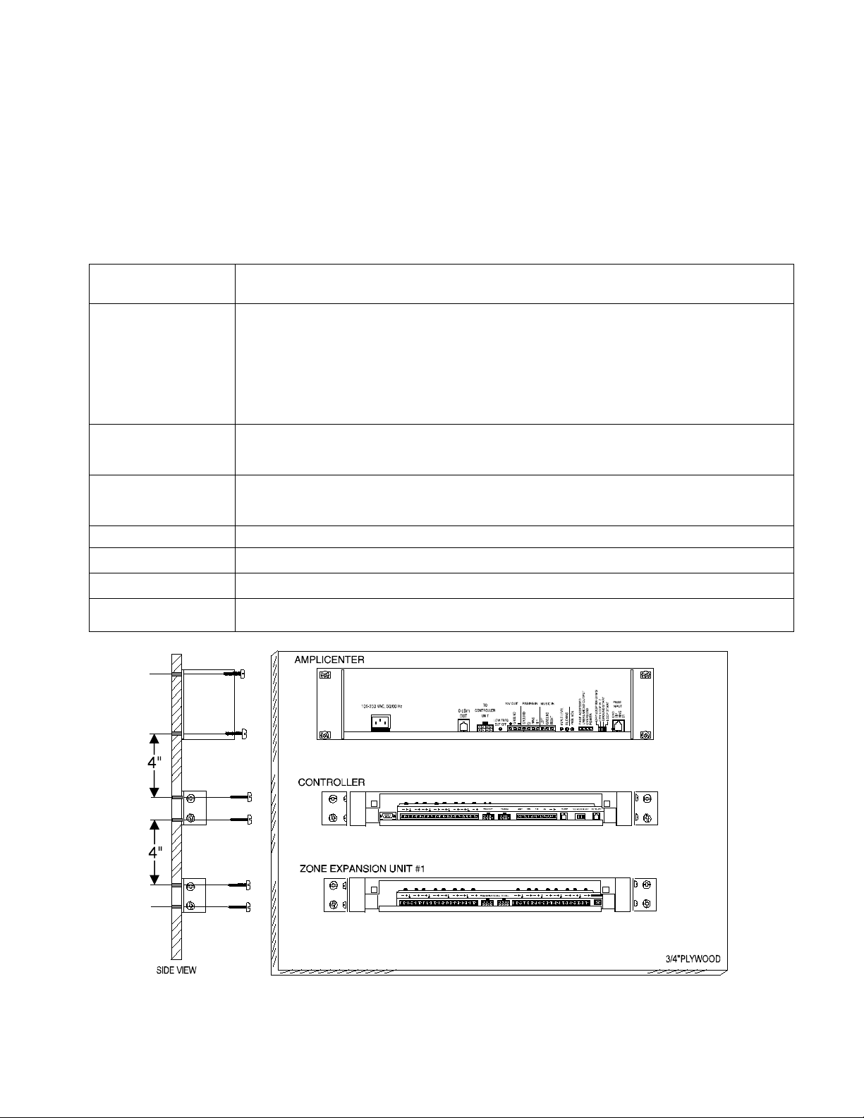
NOTE: When installing the Zone Expansion
Unit, leave at least four inches of space above
and below for proper ventilation.
Installing the paging equipment in a ventilated
room where there is easy access to speaker
cabling (preferably in the telephone equipment
room). Disconnect all power before installing
equipment.
1. Mount the Zone Expansion Unit(s) (ZEU) to
either a wall, cabinet or a rack (below the
controller).
2. Connect 8-pin Molex from Controller to first
ZEU, and next ZEUs, if used.
NOTE: Up to 3 ZEUs can be used, providing
up to 56 paging and/or control zones.
3. Set DIP switches on each ZEU(s).
4. Set the Zone Option switches on the
Controller and ZEU(s).
NOTE: For each zone used, no matter what
its function, this switch needs to be set to one
of three settings for proper zone operation
before applying power to the system.
The Controller has eight switches for zones 1-8.
Each subsequent ZEU has switches for zones
9-24, 25-40 and 41-56.
Refer to the Zone Map and Zone Configuration
Tables filled out during facility paging system
design. You can find these in the PagePac®
System Installation and Configuration Guide.
5. Locate and mount all speakers in accordance
with the floor plan drawing for this
installation.
6. Connect each speaker to the appropriate
Home Run or Speaker-to-Speaker wiring
scheme as shown on the floor plan.
NOTE: Adjust all speakers per volume and
power requirements as noted on floor plan,
during or after installation.
1 947187
Page 2

Figures 7 and 8 show wiring methods using
local and zone connector blocks, and contact
closure zone applications.
7. Test speaker wiring for short circuits.
Measure the resistance of each Home Run
wiring with an ohmmeter. Any pair indicating
a value of less than 15 Ohms must be
rechecked for possible shorted wiring or
speakers. Correct any problems and retest.
8. Make zone connections to Controller and
ZEU (see Figures 5 thru 7).
The zone connectors on the Controller and
ZEU can accommodate up to two 22 AWG
wires or four 24 AWG wires per zone output.
Check zone option switch setting with Zone
Map and Zone Configuration tables as you
connect each zone.
NOTE: DO NOT over tighten zone
connector screws.
2. Begin programming the Controller.
A quick reference card for telephone
programming, along with detailed programming
instructions, can be found in the PagePac Plus
System Installation and Configuration Guide,
Programming.
TROUBLESHOOTING
Some common problems encountered when the
paging system is not operating are described
below. Check each item in the order listed.
1. No AC power to AmpliCenter or Controller
(they supply power to the ZEU(s)).
2. Host telephone system failure.
3. Host system page port failure.
4. A hardwire disconnect between host system
and Controller.
5. AmpliCenter, Controller or ZEU zone
switches or DIP switch settings tampered
with.
Powering Up System
With all zones wired and connected to the
Controller and ZEU(s), initial testing can begin.
Once initial testing is done, you can begin to
program the Controller with the features for each
zone.
1. Plug the power cord into the AC input
connector on the AmpliCenter®. the following
should happen:
a. The green Power LED on the
AmpliCenter will turn on and stay on.
b. The green Page Access LED on the
AmpliCenter also turns on, but will go out
after a few seconds.
c. On the Controller, verify that the green
Phone System Enabled LED is off.
d. On the Controller, verify that the yellow
Attendant Access Enabled LED is off.
e. The green Power LED on the ZEU(s) will
turn on and stay on.
NOTE: If during power up, the system does
not respond as described, refer to the
Troubleshooting section of this guide and/or
the PagePac® Plus System Installation and
Configuration guide for detailed
troubleshooting.
If the problem has not been resolved by checking
the preceding items, refer to the troubleshooting
tables in the PagePac Plus Installation and
Configuration Guide.
Controls and Indicators, Terminals
and Connectors
Figure 9 shows the controls and indicators,
terminals and connectors on the rear panel of the
ZEU(s). Table 1 identifies them by function.
Table 1. Controls and Indicators, Terminals
and Connectors
1 Zone option 3-position slide switch: 70V audio
out, contact closure input and contact closure
output.
2 Zone connector for expansion zones: plus,
minus and ground screw terminals.
3 8-pin Molex connector from controller: power,
control and audio or previous ZEU.
4 8-pin Molex connector to additional ZEU:
power, control and audio.
5 DIP switch to be set when one, two or three
ZEU(s) are used.
2
Page 3
TECHNICAL ASSISTANCE
When calling, have a VOM and a telephone test
set available and call from the job site. Call (540)
563-2000 and press 1 for PagePac Technical
Support or visit our websites at
http://www.pagepac.com and www.valcom.com.
Should repairs be necessary, attach a tag to the
unit clearly stating company name, address,
phone number, contact person and the nature of
the problem. Send the unit to:
Valcom, Inc.
PagePac
®
Repair Dept.
5614 Hollins Road
Roanoke, VA 24019-5056
Table 2. ZEU Specifications
Capacities Each ZEU connects up to 16 zones of audio output (including talkback), contact
closure outputs or inputs.
Dimensions and
Height: 1.75” (4.45cm)
Weights
Width: 16.00” (40.64cm); 19.00’ (48.26cm) with brackets attached
Depth: 6.88” (17.48cm)
Weight: 3.0 lbs (1.36kg)
Electrical Relay
Control Contact Closure: Contacts are rated at 120VAC/50VDC at 1 Amp
Contacts
Audio Zone: Contacts are rated at 2 Amps
Temperature Range 0 to +40° C (+32 to +104° F) operational
-40 to +66° C (-40 to +150° F) storage and shipment
Humidity Range 5 to 95% (non-condensing) storage/shipment and operation
Altitude Sea level to 10,000 ft. operational (1048 to 648 millibars) 40,000 ft. max. shipment
Environmental Locate in an area free of excess moisture, corrosive gases, dust and chemicals.
Interconnect Cable 8-position, 5 Amp contact rating, locking, keyed, 22 AWG wire, housing material
94V-2, providing 70.0VrmS (4), common ground, +17VDC, Serial Data and Clock Data
Figure 1. Wall Mounted Hardware
3
Page 4

FRONT DETAIL
REAR DETAIL
ZONE
WIRING
TEL LINE
INPUT
CHANNELS
PagePac Plus
AmpliCenter D300
PagePac Plus
Controller
Call Stacker
POWER
TYPICAL
19''
4.0"
COMBINATION
PAN HEAD
PILOT POINT
# 12 - 24 (TYPICAL)
PagePac Plus
AmpliCenter D300
POWER
PagePac Plus
Controller
Call Stacker
10''
POWER STRIP
Figure 2. Rack Mounted Hardware
Figure 3. 8-pin Molex Connector from Controller to Zone Expansion Unit(s)
4
Page 5

Figure 4. Setting Zone Expansion Unit Dip Switches
Figure 5. Setting Zone Option Switches on Controller and Zone Expansion Units
5
Page 6

Figure 6. Speaker Wiring Methods
Figure 7. Zone Wiring Using Connector Blocks
6
Page 7

INPUT
CONTACT
CLOSURE
Figure 8. Speaker and Contact Closure Zone Wiring to Controller
Figure 9. Zone Expansion Unit Back Panel
7
Page 8

VALCOM LIMITED WARRANTY
Valcom, Inc. warrants its products to be free from defects in materials and workmanship under conditions of normal
use and service for a period of one year from the date of shipment. The obligation under this warranty shall be
limited to the replacement, repair or refund of any such defective device within the warranty period, provided that:
1. inspection by Valcom, Inc. indicates the validity of the claim;
2. the defect is not the result of damage, misuse, or negligence after the original shipment;
3. the product has not been altered in any way or repaired by others and that factory sealed units are
unopened (a service charge plus parts and labor will be applied to units defaced or physically damaged);
4. freight charges for the return of products to Valcom are prepaid;
5. all units ‘out of warranty’ are subject to a service charge. The service charge will cover minor repairs (major
repairs will be subject to additional charges for parts and labor).
This warranty is in lieu of and excludes all other warranties, expressed or implied and in no event shall
Valcom, Inc. be liable for any anticipated profits, consequential damages, loss of time or other losses
incurred by the buyer in connection with the purchase, operation, or use of the product.
This warranty specifically excludes damage incurred in shipment. In the event a product is received in damaged
condition, the carrier should be notified immediately. Claims for such damage should be filed with the carrier
involved in accordance with the F.O.B. point.
Headquarters: In Canada
Valcom, Inc. CMX Corporation
5614 Hollins Road 35 Van Kirk Drive #11 and 12
Roanoke, VA 24019-5056 Brampton, Ontario L7A 1A5
Phone: (540) 563-2000 Phone: (905) 456-1072
FAX: (540) 362-9800 FAX: (905) 456-2269
8
 Loading...