

Page 1

®
PagePac
by
PAGEPAC PLUS CONTROLLER (V-5323100) AND
CONTROLLER WITH POWER SUPPLY (V-5323105)
INTRODUCTION
The PagePac® Plus System consists of the Controller,
AmpliCenter, and up to 3 Zone Expansion Units, providing up
to 56 paging and/or control zones. The self powered
Controller comes with its own power supply, enabling
it to control paging and control zones utilizing a paging amplifier
other than the AmpliCenter.
Dimensions/Weight
• 16.00”W x 1.80”H x 6.90”D
(40.64cm x 4.57cm x 17.53cm)
2.00 lbs. (0.91 kg)
ISSUE 2
SPECIFICATIONS
FEATURES
• 8 Zones Paging or Control • Night Bell
• Contact Closure Inputs or Outputs • 7 Alert Tones
• Loop Start, Ground Start C O Port, Analog Station • Page Zone Groups
or Dry Loop Access (page port with contact closure) • Flexible Numbering Plan
• Controller with Power Supply for Applications with
Distributed Amplified Speakers or Amplifiers other than PagePac
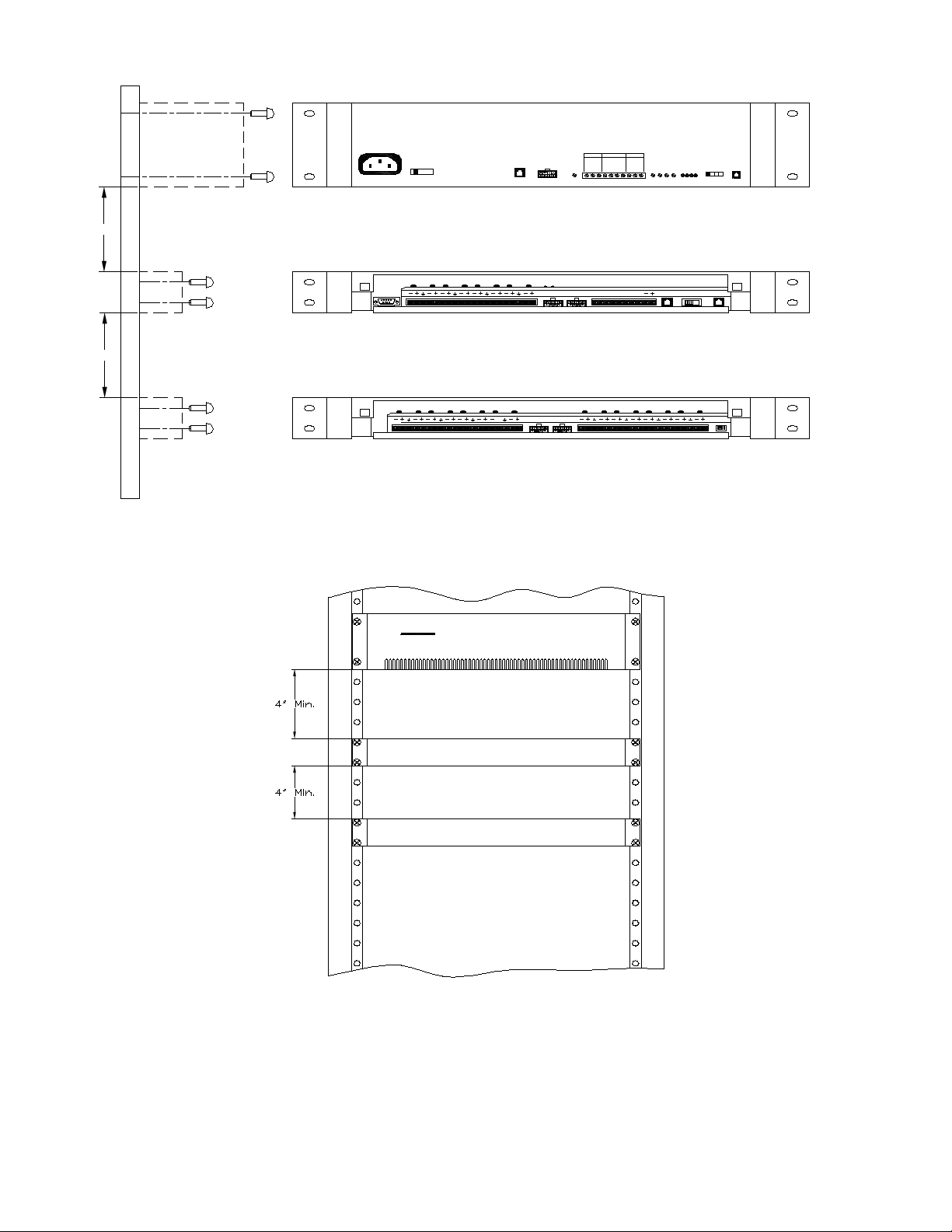
INSTALLATION
1. Mount the PagePac® Plus Controller and Zone Expansion Units, if any, to either a wall
(see Figure 1), cabinet or a rack (below the AmpliCenter or other amplifier) (see Figure 2).
Note: When installing the PagePac Plus Controller, leave at least four inches of space above and below
for proper ventilation.
Install the paging equipment in a ventilated room where there is easy access to speaker cabling (preferably in the telephone equipment room).
1 947180
Page 2
4"
4"
105-120 VAC
210-240 VAC
50-60 HZ
115 V
230 V
8.0 A
4.0 A
60 HZ
50 HZ
TO CONTROLLER
O DBM
OUT
UNIT
LOW FREQ
OUTPUT
TO POWER
TO Z.E.U.
AMP
FROM
TO
PREVIOUS
NEXT
CONTROLLER
CONTRO LLER
Figure 1. Wall Mounted Hardware
70V OUT
+
D-SERIES
AMPLICENTER
MUSIC IN
PAG ING IN
RING
GROUND
LEFT
GROUND
C1
GROUND
RIGHT
-
TIP
INPUT LEVEL
PAGE VOX
CAL
DUCKING
TO AMP TELE MODE TO TEL
N.B.
0dBm
0dBu
AA
D.L.S.A. G.L.L.S.
DRY LOOP 600 OHM
UNBALANCE OUTPUT
OVERLOAD
POWER
PAGE ACCESSED
ZONE EXPANSION UNIT
DRY LOOP HI Z
SYSTEMSELECT
GROUND START
LOOP START
PAGE IN
RING
GROUND
TIP
C1
CONTROLLER
ALCOMV
PagePac Plus
D-SERIES AMPLICENTER
PagePac Plus
CONTROLLER
PagePac Plus
ZONE EXPANSION UNIT
Figure 2. Rack mounted Hardware
2.Connect background music input wires to Left and Right terminals if stereo or Left and Ground if not.
See Figure 3
Note: The optional audio source can be a CD or tape player, AM, FM, or commercial radio, or other audio
source.
2
Page 3
If more than one AmpliCenter is used in the paging system, each one can be connected to the same music or
audio source, or different audio sources, if desired.
7 0 V O U T P A G IN G IN M U S IC IN
LOW F RE Q
OUTPUT
+
GROUND
-
MONO
GROUND
+
-
C1
RING
LEFT
GROUND
TIP
OR
RIGHT
INPUT LEVEL
-
STEREO
+
PAGE VOX
DUCKING
+
-
CAL
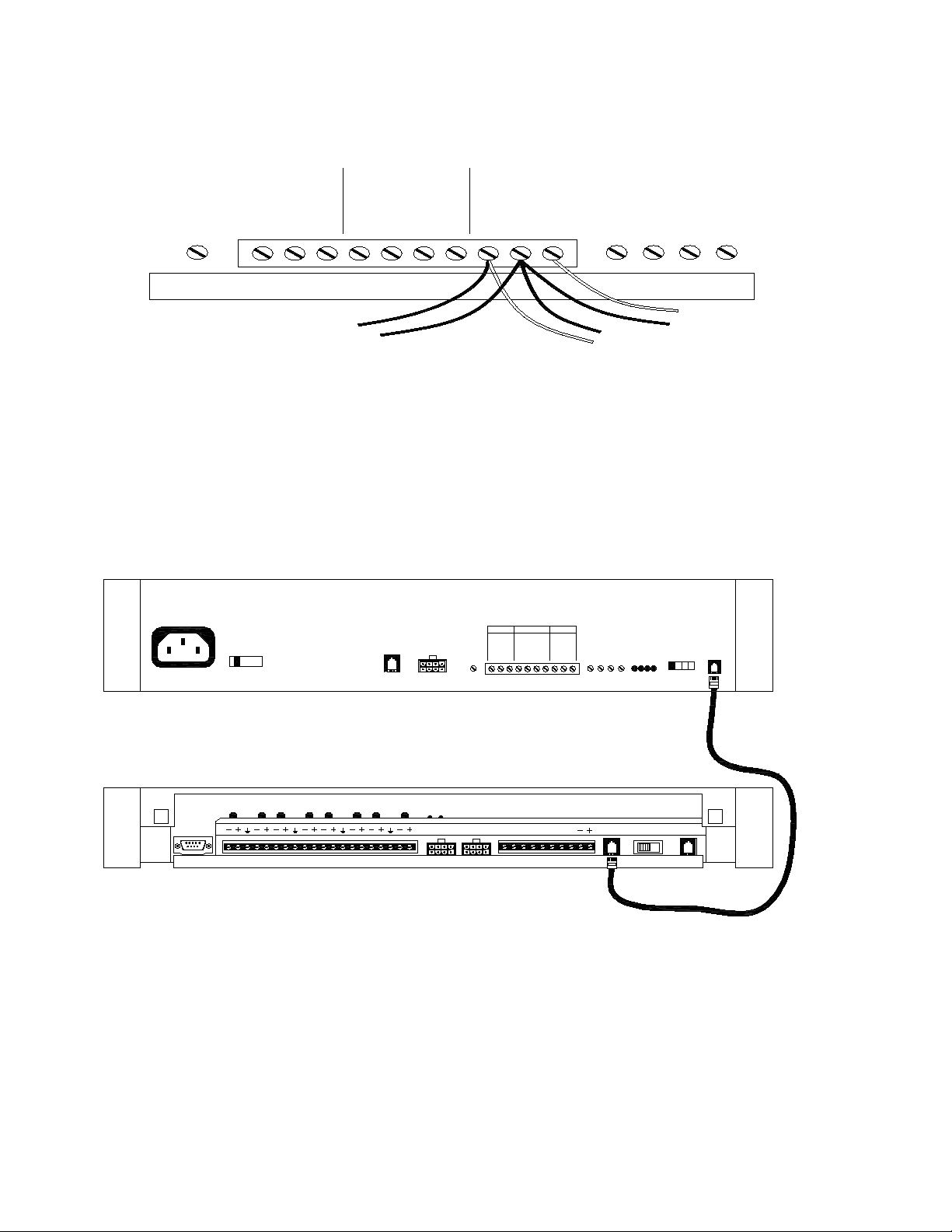
3. Plug modular cord into connectors “To Amp” on Controller and “Page In” on AmpliCenter
(see Figure 4).
Note: If an amplifier other than the AmpliCenter is used, refer to page 10, Figure 16. There you will find
wiring diagrams and notes.
AMPLICENTER
105-120 VAC
210-240 VAC
50-60 HZ
115 V
8.0 A
60 HZ
230 V
4.0 A
50 HZ
O DBM
OUT
TO CONTROLLER
UNIT
LOW FREQ
OUTPUT
70V OUT
+
GROUND
PAGING IN MUSIC IN
RING
GROUND
C1
-
TIP
LEFT
GROUND
RIGHT
INPUT LEVEL
UNBALANCE OUTPUT
OVERLOAD
POWER
PAGE ACCESSED
PAGE VOX
CAL
DUCKING
PAGE IN
GROUND
RING
TIP
C1
GROUND START
LOOP START
DRY LOOP HI Z
DRY LOOP 600 OHM
652134
CONTROLLER
TO POWER
AMP
TO Z.E.U.
0dBm
N.B.
0dBu
TO AMP TELE MODE TO TEL
AA
621534
Figure 4. Page In Connection from Controller to AmpliCenter
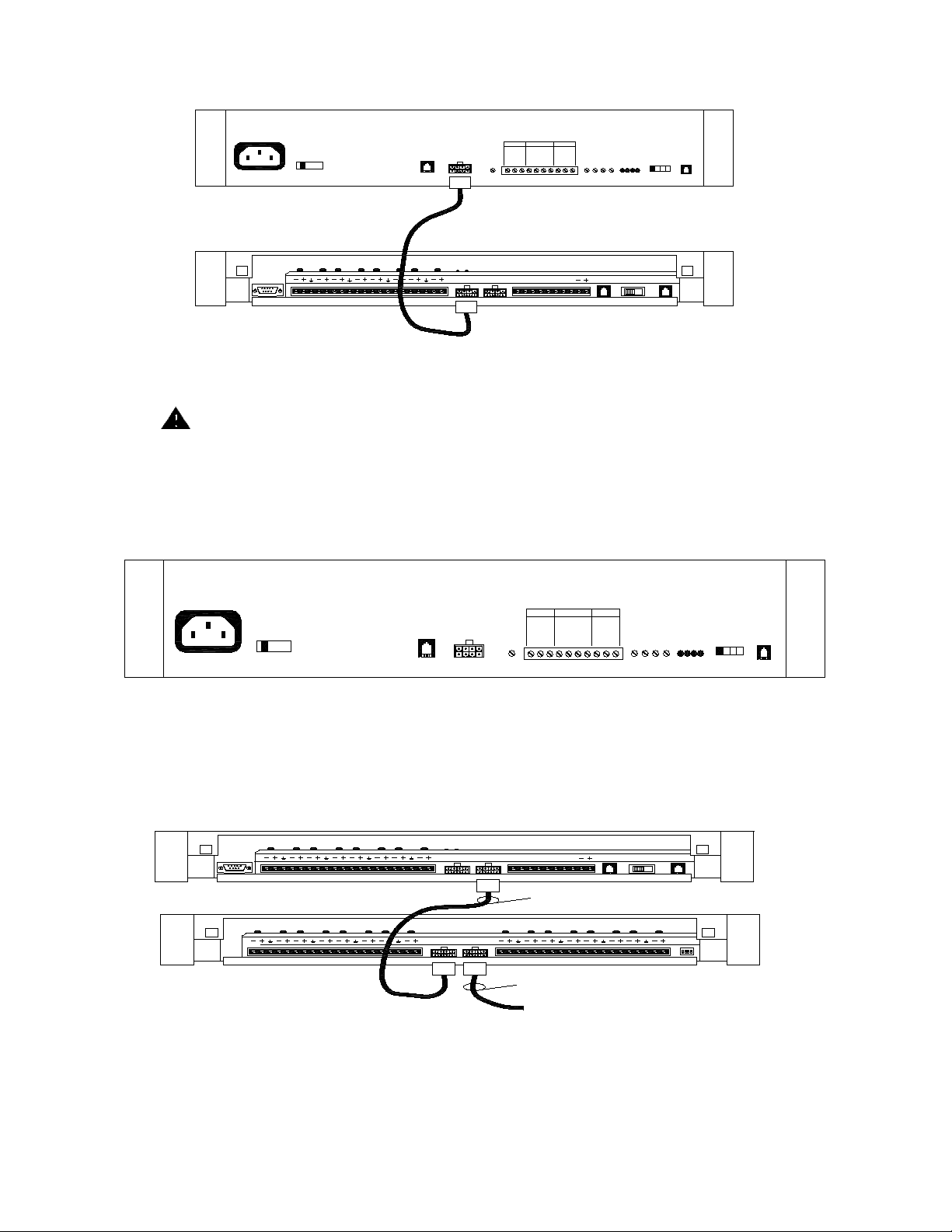
4.Connect 8-pin Molex connector from AmpliCenter to Controller (see Figure 5).
Note: Connectors can only go in one way. DO NOT force in.
If you are using another type of amplifier, refer to page 10 Figure 16.
3
D.L. S.A. G.L. L.S.
SYSTEMSELECT
Page 4
AMPLICENTER
105-120 VAC
210-240 VAC
50-60 HZ
CONTROLLER
PAGING IN MUSIC IN
115 V
230 V
8.0 A
4.0 A
60 HZ
50 HZ
O DBM
OUT
TO CONTROLLER
UNIT
LOW FREQ
OUTPUT
70V OUT
+
RING
LEFT
GROUND
GROUND
-
RIGHT
GROUND
C1
TIP
UNBALANCE OUTPUT
PAGE ACCESSED
INPUT LEVEL
PAGE VOX
CAL
DUCKING
PAGE IN
GROUND
RING
TIP
C1
GROUND START
LOOP START
DRY LOOP HI Z
DRY LOOP 600 OHM
OVERLOAD
POWER
TO POWER
AMP
TO Z.E.U.
0dBm
N.B.
0dBu
AA
TO AMP TELE MODE TO TEL
D.L. S.A.G.L. L.S.
SYSTEMSELECT
Figure 5. 8-pin Molex Connector from AmpliCenter to Controller
CAUTION
Damage to Controller will occur if the Molex connector (from AmpliCenter) is
pluggedInto the right connector (This goes from Controller to Zone Expansion Unit).
1 .Set the AmpliCenter Telephone Mode Selection Switch to Dry Loop 600 Ohms (Far left setting).
see Figure 6.
AMPLICENTER
105-120 VAC
210-240 VAC
50-60 HZ
115 V
8.0 A
60 HZ
230 V
4.0 A
50 HZ
O DBM
OUT
TO CONTROLLER
UNIT
70V OUT PAGING IN MUSIC IN
LOW FREQ
+
OUTPUT
GROUND
RING
GROUND
C1
LEFT
GROUND
-
RIGHT
TIP
INPUT LEVEL
UNBALANCE OUTPUT
OVERLOAD
POWER
PAGE ACCESSED
PAGE VOX
CAL
DUCKING
PAGE IN
GROUND
GROUND START
LOOP START
DRY LOOP HI Z
DRY LOOP 600 OHM
RING
TIP
C1
Figure 6. AmpliCenter Mode Switch Setting
2. Connect 8-pin Molex from Controller to Zone Expansion Unit(s), if used. See Figure 7.
Note: Up to 3 Zone Expansion Units can be used, providing up to 56 paging and/or control zones.
CONTROLLER
TO POWER
ZONE EXPANSION UNIT
FROM
PREVIOUS
CONTROLLER
AMP
CONTROLLER
TO Z.E.U.
0dBm
N.B.
0dBu
POWER CONTROL 70V AUDIO
TO
NEXT
POWER CONTROL 70V AUDIO
TO NEXT ZONE EXPANSIO N UNIT(S)
TO AMP TELE MODE TO TEL
AA
D.L.S.A.G.L.L.S.
SYSTEMSELECT
Figure 7. 8-pin Molex Connector from Controller to Zone Expansion Unit(s)
3. Set DIP switches on each Zone Expansion Unit, if any. See Figure 8.
4
Page 5
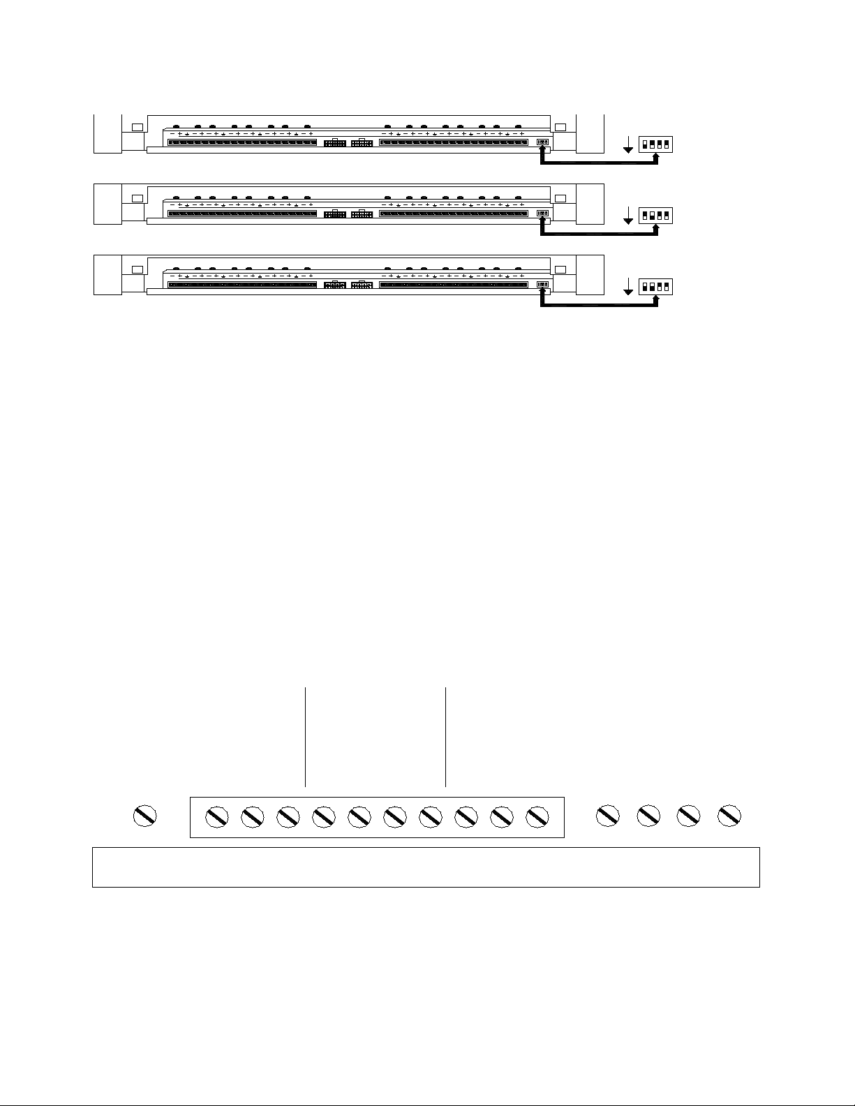
Note: These DIP switches must be set correctly in order for the Controller to recognize the additional
zones.
FROM
TO
PREVIOUS
NEXT
CONTROLLER
CONTROLLER
ON 2nd ZONE EXPANSIO N UNIT SET DIP SW ITCH TO
FROM
TO
PREVIOUS
NEXT
CONTROLLER
CONTROLLER
ON 3rd ZONE EXPANSION UNIT SET DIP SW ITCH TO
TO
FROM
PREVIOUS
NEXT
CONTROLLER
CONTROLLER
ON
ON
ON
12 43
1234
ENABLES
ZONES 9-24
ENABLES
ZONE S 25-40
4321
ENABLES
ZONE S 41-56
Figure 8. Setting Zone Expansion Unit DIP Switches
4. Using a small standard screwdriver, make the following adjustments:
A. Adjust the Low Frequency Cut Off control to center position. This control cuts out the low frequency
bass so that horns and small speakers are not over-driven and distorted by excessive bass energy. Cutoff frequency is continuously adjustable from 50Hz (full CCW rotation) to 400 Hz (full CW rotation). See
Figure 9.
B. Adjust Music Input level to the center position. Clockwise rotation will increase the level. Listen and
set to a comfortable level. (Make sure the music input is not too high check for the overload light on
amp).
C. Adjust Music Ducking level to the fully counterclockwise position. This feature allows music to
continue to be heard during a page, but at a reduced level. The range is less than –40dB (full CCW) to –
6dB (full CW). If music is not
connected, set to full CCW.
D. Adjust the Page VOX (voiceactivated) sensitivity to the fully counterclockwise position.
E. Adjust page call to increase page volume or to lower page levels if overload light is on.
70V OUT PAGING IN MUSIC IN
LOW FREQ
OUTPUT
+
GROUND
-
GROUND
Figure 9. Sound Level Adjustments on AmpliCenter
5. Set Telephone Mode switch on Controller to match host telephone system interface port type.
C1
5
RING
TIP
LEFT
GROUND
RIGHT
INPUT LEVEL
DUCKING
PAGE VOX
CAL
Page 6
See Figure 10.
CONTROLLER
TO POWER
AMP
TO Z.E.U.
0dBm
0dBu
N.B.
TO AMP TELE MODE TO TEL
AA
D.L. S.A. G.L. L. S.
SYSTEMSELECT
DL=Dry Loop 600 ohms
LSSA/DL GS
CO600
SA/CO=Station Access/CO
GS=Ground Start Trunk Port
LS=Loop Start Trunk Port
Figure 10. Setting Controller Telephone Mode Switch
6. Connect cable from host telephone system to Controller Page Input. See Figure 11.
Note: Depending on the type of host telephone system interface port, the connection may differ slightly
from the illustration to the right. A direct 4-conductor cord from the Controller to the telephone system
can also be used, bypassing the connector block.
6
Page 7
CONTROLLER
TO POWER
AMP
TO Z.E.U.
0dBm
0dBu
TO AMP TELE MODE TO TEL
N.B.
AA
D.L. S.A. G.L. L. S.
CONNECTION TO HOST
TELEPHONE SYSTEM
SYSTEMSELECT
621534
CONNECT GREEN WIRE TO SYSTEM TIP T
CONNECT RED WIRE TO SYSTEM RING R
CONNECT BLACK WIRE TO THE DRY CONTACT CONTROL LEAD GROUND
CONNECT YELLOW WIRE TO THE DRY CONTACT CONTROL LEAD C1
BLACK
GREEN
RED
YELLOW
1
2
3
4
5
6
TO HOST TELEPHONE
SYSTEM INTERFACE
PORT
Figure 11. Connecting Host Telephone System to Controller
7. Connect two wires from the night bell analog station port on the host telephone system to Controller night
bell (N.B.) input. See Figure 12. (Analog station port needs to provide 90 VAC ring voltage)
CONTROLLER
TO POWER
AMP
TO Z.E.U.
0dBm
0dBu
N.B.
TO AMPTELE MODETO TEL
AA
D.L. S.A. G.L. L.S.
SYSTEMSELECT
NIGHT BELL CONNECTION
FROM HOST TELEPHONE
SYSTEM ANALOG STATI ON
PORT.
Figure 12. Night Bell Connection to Controller
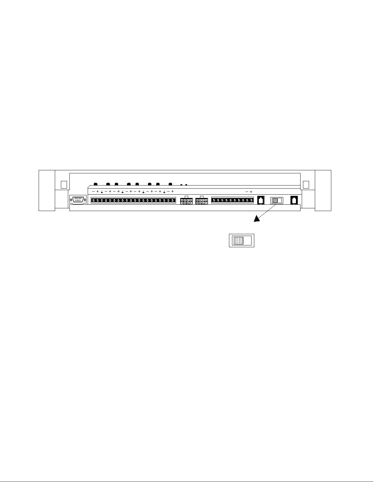
8. Set the Zone Option switches on the Controller and Zone Expansion Units, if any.
Note: For each zone used, no matter what its function, this switch needs to be set to one of three settings for proper zone operation.
The Controller has eight switches for zones 1-8. Each subsequent Zone Expansion Unit has switches for zones
9-24, 25-40, and 41-56.
7
Page 8
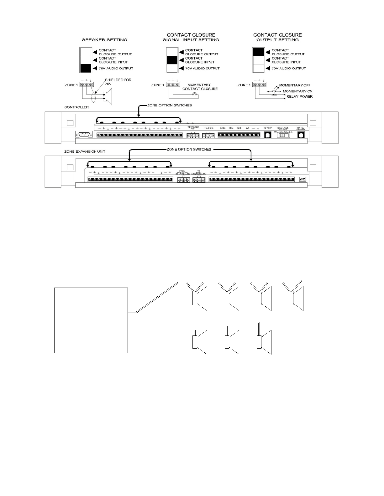
Figure 13. Setting Zone Option Switches on Controller and Zone Expansion Units
CONNECTING SPEAKERS
Connect each speaker to the appropriate Home Run or Speaker-to-speaker wiring method as shown on the
floor plan. See Figure 14. (use shielded wire for 70 volt speaker wiring)
SPEAKER-TO-SPEAKER METHOD
70V VOLT
AUDIO
OUTPUT
HOME RUN METHOD
Figure 14. Speaker Wiring Methods
8
Page 9
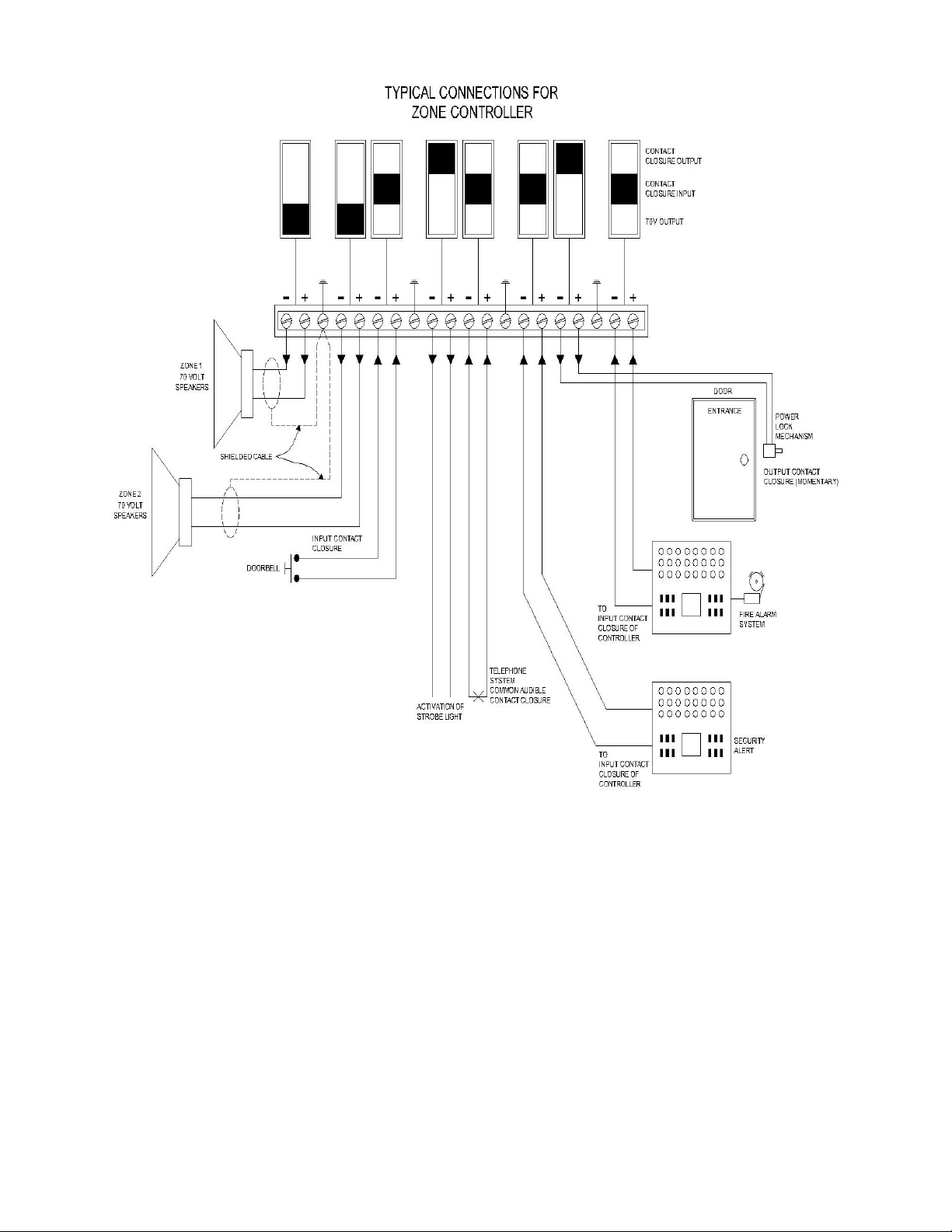
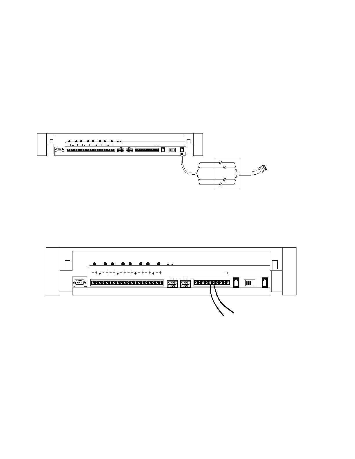
Figure 15. 70 volt Speaker and Contact Closure Zone Wiring to Controller
3. Test speaker wiring for short circuits.
Measure the resistance of each home run wiring with an ohmmeter. Any pair indicating a value of less than 15
Ohms must be rechecked for possible shorted wiring or speakers. Correct any problems and retest.
4. Make zone connections to Controller and any Zone Expansion Units. See Figure 15.
The zone connectors on the Controller and Zone Expansion Units can accommodate up to two 22 AWG wires or
four 24 AWG wires per zone output.
Note: DO NOT over tighten zone connector screws.
Check zone option switch setting with Zone Map and Zone Configuration Tables as you connect each zone (A
70V audio output setting going to other than speakers may damage other equipment).
9
Page 10

POWERING UP SYSTEM
With all zones wired and connected to the Controller and Zone Expansion Units (if any), initial testing can begin.
Refer to Controls and Indicators, Terminals and Connector. Once initial testing is done, you can begin to
program the Controller with the features for each zone.
1.Plug the power cord into the AC input connector on the AmpliCenter. The following should happen:
A. The green Power LED on the AmpliCenter will turn on and stay on.
B. The green Page Access LED on the AmpliCenter also turns on, but will go out after a
few seconds.
C. On the Controller, verify that the green Phone System Enabled LED is off, and that the
yellow Attendant Access Enabled LED is off.
D. If background music is connected, adjust the Music In Input Level control on the
AmpliCenter(s) for an acceptable level.
NOTE: If an amplifier other than the AmpliCenter is used, make sure it is powered up and verify the
Controller LEDs.
2. Make an All Zone test page. Readjust sound levels by adjusting speaker tap settings, if
required.
A. Readjust Music Input level to the desired loudness relative to paging loudness.
B. Some loudspeaker taps may have to be re-adjusted to get even coverage at all
Locations. Be sure that the final speaker tap setting totals do not exceed the power
Rating of the Amplicenter.
3. Begin programming the Controller (refer to Programming Section).
locations.
SELF-POWERED CONTROLLER CONNECTIONS
The wiring diagrams in Figures 16 through 18 illustrate the connection of the Self-Powered Controller with other
amplifiers. In this way, most features associated with the Controller can be utilized with amplifiers other than the
AmpliCenter. Refer to Tables 1 and 2 for gain and sensitivity settings.
CONTROLLER WITH POWER SUPPLY TO GENERIC AMPLIFIER
To install the Controller to a Generic Amplifier (see Page 10, Figure 16):
1. Connect 0dBu or 0dBm output to amplifier audio input.
Note: Refer to Table 1 for controller audio output levels and volume control settings.
2. Connect Amplifier Audio Output (70.7V) to Amplified Audio Input on Controller.
3. Adjust Controller volume control (see Table 1).
4. If required, connect control input to amplifier from Controller zone set to “output contact closure program for
system HS (program 70).
5. Connect background music if needed to music input.
6. Connect host telephone system to Controller.
7. Plug power pack connector into Controller.
10
Page 11
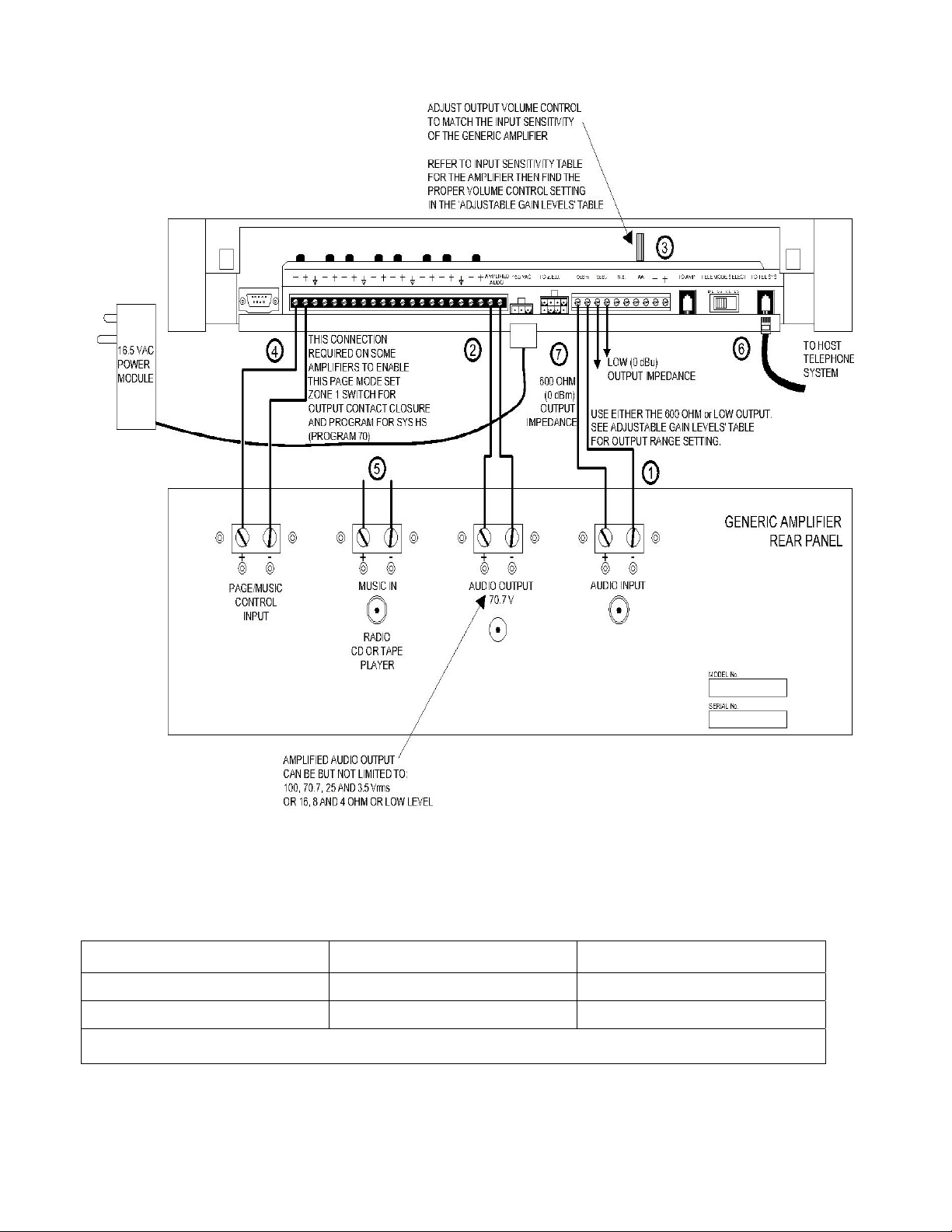
Figure 16. Connection of the Self-Powered Controller to Generic Amplifiers
Table 1. Controller Adjustable Output Level
Controller Volume Control Setting 600 Ohm Impedance Output Low Impedance Output
Full Counter Clockwise - 12dBm (195mVrms) - 6dBu (388mVrms)
Full Clockwise 0dBm (.775Vrms) + 6dBu (1.50Vrms)
Note: The generic amplifiers input must be dry, no battery or voltage can be present.
11
Page 12

CONTROLLER WITH POWER SUPPLY TO AMPLIFIED SPEAKERS
To install a Controller to Amplified Speakers (see Figure 17):
1. Connect 0dBu output of Controller to Amplified Audio input of Controller.
2. Adjust Controller volume control to mid point.
3. Connect amplified speakers audio input to each zone connector.
4. Set zone option switches to Amplified Audio Output.
5. Connect host telephone system to Controller.
6. Plug Power Pack connector into Controller.
12
Page 13

13
Page 14

Figure 17. Self-Powered Controller Driving Amplified Speakers
CONTROLLER WITH POWER SUPPLY TO D-SERIES AMPLICENTER
To install a Controller to a D-Series AmpliCenter (see Figure 18):
1. Connect 6-conductor cord from Controller (To Amp) to AmpliCenter Page Input.
2. Connect 70V audio out from AmpliCenter to Amplified Audio, input of controller.
3. Connect host telephone system input to Controller.
4. Connect background music if needed to music input,of AmpliCenter.
5. Plug power pack connector into Controller.
14
Page 15

15
Page 16

D-SERIES
AMPLI CENTER
105-120 VAC
210-240 VAC
50-60 HZ
115 V
8.0 A
60 HZ
230 V
4.0 A
50 HZ
O DBM
OUT
TO CONTROLLER
UNIT
LOW FREQ
OUTPUT
70V OUT
GROUND
+
-
PAGING IN
GROUND
C1
MUSIC IN
RING
LEFT
GROUND
RIGHT
TIP
INPUT LEVEL
DUCKING
PAGE VOX
CAL
OVERLOAD
UNBALANCE OUTPUT
PAGE ACCESSED
PAGE IN
RING
GROUND
TIP
C1
GROUND START
LOOP START
DRY LOOP HI Z
DRY LOOP 600 OHM
POWER
652134
4312 56
16. 5 VAC
POWER
MODULE
SELF-POWERED
CONTROLLER
AMPLI FIED
AUDIO
AMPLIFIED
AUDIO
16.5 VAC
2
TO Z.E.U.
5
0dBm
1
PAGE INTO
4
N.B.
0dBu
TO AMP
AA
216534
TELE MODE SELECT
G.L.S.A.D.L. L.S.
TO TEL SYS
3
AMPLI FIER
214356
TO HOST
TELEPHONE
SYSTEM
Figure 18. Self-Powered Controller Connected to the PagePac D-Series AmpliCenter
PROGRAMMING THE CONTROLLER
The Controller is programmed to enable each zone to have different zone features, if required. There are two
ways to do the programming. One is via the RS-232 serial port on the Controller which is connected to an IBM
compatible (DOS) PC using the optional programming software.
An advantage of using a PC to configure the Controller is that screens can be viewed on the monitor to aid in
selecting the zones for various options. A re-programming of the entire system can be done before downloading
the configuration to the controller, saving down time. Furthermore, the old configuration can be saved and used
again.
16
Page 17

The other method works via the telephone access port (like calling to make a page), which accepts only
touchtone telephone keypad inputs (DTMF) tones. The Controller has the ability to retain all programming
options in non-volatile EEPROM memory or as a .CFG (configuration) file on a personal computer.
PROGRAMMING STEPS
CAUTION
The Zone Option switches must be set before the system is powered up, and therefore before
programming the system.
The Zone Option switches on the rear of the Controller and Zone Expansion units must be set to match the zone
option selected for programming. The slide switch for each zone must be manually set to Contact Closure (to
switch on/off a device, such as a door security lock, remote amplifier, etc.), Input Contact Closure, or Audio
Output, depending on the mode selected for each zone.
IMPORTANT! It is recommended that the paging zone decisions be made and filled in on the Zone Map and
Configuration Tables, located on pages 25-29 prior to setting zone option switches and
ENTER PROGRAMMING MODE
* *
1. From any DTMF telephone in the system, dial the paging access extension.
2. Dial the Connect Password (if optioned).
You will hear the paging system dial tone.
3. Dial
Note: you will hear conformation tone. Now programming may begin.
* *
programming.
1 0 RESET TO FACTORY DEFAULTS
1. Dial 1 0
You will hear two beeps from the Controller.
2. Dial 2 5 3 2 7
After a long pause, you will hear three beeps from the Controller. The controller is now set to factory default
conditions.
3. Program the system options (refer to the following paragraphs).
You may exit the programming mode by dialing #.
2 0 DEFINE LENGTH OF ALIAS NUMBERS
This system option allows you to set the length (3 or 4 digits) of the ALIAS number field. The default is 2 digits. If
you wish to assign ALIAS numbers to the paging zones, you must set the length parameter. The ALIAS number
is the dialing extension for the zone. If no ALIAS numbers are used, the Physical Zone Code is the dialing
extension for a zone.
Note: This MUST be done before “Zone Map Option – Assigning ALIAS Numbers,” later in this section.
1. Dial 20 to select this option.
Hear a DOUBLE beep.
Press 3 or 4 to set length of ALIAS numbers (number of digits dialed to reach paging zone).
Hear TRIPLE beeps.
2. To verify the setting, dial 2 1 and repeat step 2 above.
2 2 SET SERIAL PORT BIT RATE
The speed (bit rate) of the controller's RS-232 serial port can be set to the rate of the computer monitor or visual
display. Default is 9600 bps. The bit rate may be changed at any time, but the Controller must be reset (power
off then on again) in order to take effect. (This is the only program change requiring the Controller to be reset).
1. Dial 2 2 to select this option
Hear a DOUBLE beep.
2. Dial a code to select the Serial Port Bit Rate
17
Page 18

0 to select 300 bps
1 to select 1200 bps
2 to select 2400 bps
3 to select 4800 bps
4 to select 9600 bps
5 to select 14400 bps
6 to select 19200 bps
Hear TRIPLE beeps.
3. To verify the status of this option, dial 2 3 and repeat step 2 above.
2 4 INHIBIT DIAL TONE DETECT
Supervision of the Station/Centrex Access mode is accomplished in 3 ways, by monitoring the loop current and
the audio signal (including dial tone), and a forced disconnect timer. This option (only applicable in the station
access mode) enables you to defeat the dial tone detect function in order to send a tone via the Telephone
Interface to the output.
1. Dial 2 4 to select this option.
Hear a DOUBLE beep.
2. Dial 0 to Enable, or 1 to Inhibit.
Hear TRIPLE beeps.
3. To verify the condition (OFF/ON) of the Dial Tone Detect option, dial 2 5 and repeat step 2
above.
3 0 SET CONNECT PASSWORD
This feature will not become active until the first time you enter a password, via the programming mode. The
factory default is NO password. The Connect password operates as a security block into the paging system,
restricting paging access to authorized users.
Note: You may want to use a short Connect password (2 or 3 digits only) for ease of use.
1. Dial 3 0 to select this option.
Hear a DOUBLE beep.
2. Enter the Password you wish to use (up to 6 digits). If the password has fewer than 6 digits, enter the # to
terminate the string.
Note: For example, 123456 is a valid password entry. 123# is also a valid password entry, resulting in
the password 123.
If you already have entered a password and want to remove it (to have NO password), just enter the # alone.
Hear TRIPLE beeps.
To verify that the new Connect password has been established, dial 3 1 and repeat step 2 above.
3 2 SET PROGRAMMING PASSWORD
Establishing a Programming password will restrict access to the programming mode of the PagePac Plus
paging system. It is recommended that access to programming be restricted to the System Administrator,
Telecommunications Manager, or other selected users.
Note: Your Connect and Programming passwords should not be the same. If this feature is active and
the system has been accessed via the telephone interface, then after the first digit of your Programming
password is pressed, the dial tone will stop and will not be returned until the correct password is
entered or until the user hangs up and re-enters the system.
This feature will become active once any programming password has been entered via the programming mode.
You are not required to establish such a password. The factory set default programming password is * *.
1. Dial 3 2 to select this option. Hear a DOUBLE beep.
2. Enter the Password you wish to use (up to 6 digits). If the password has fewer than 6 digits,
enter the # to terminate the string.
NOTE: For example, 234567 is a valid password entry. 234# is also a valid password entry, resulting in
the password 234.
18
Page 19

If you already have entered a password and now want to remove it (to have NO password), just enter the #
alone. Hear TRIPLE beeps.
3. To verify that the new Programming password has been established, dial 3 3 and repeat step
2 above.
Forgot the Password? If either or both the connect password and programming password are forgotten, it will
be necessary to call the Help line (refer to page ii) for instructions how to erase the two passwords and be able
to enter new ones.
4 0 TURN CONFIRMATION TONE ON/OFF
When the option is ON, a tone will be sent to the telephone interface after a zone has been selected and before
a page can be made. The default setting is ON.
1. Dial 4 0 to select this option. Hear a DOUBLE beep.
2. Dial 0 to turn OFF, or 1 to turn ON. Hear TRIPLE beeps.
3. To verify the Confirmation Tone condition (OFF or ON), dial 4 1 and repeat step 2 above.
4 2 TURN PRE-ANNOUNCEMENT TONE ON/OFF
This tone is very similar to the initial talk-back warning tone, in the sense that it is sent to a zone when the zone
is accessed. This tone will be sent out to both speakers in the zone selected and to the telephone interface.
After this tone is sent, you may begin your page message. Default is ON.
1. Dial 4 2 to select this option. Hear a DOUBLE beep.
2. Dial 0 to turn OFF, or 1 to turn ON. Hear TRIPLE beeps.
3. To verify the Pre- Announcement Tone condition (OFF or ON), dial 4 3 and repeat step 2 above.
4 4 SET TALKBACK WARNING TONE
This tone is intended to alert a person that their conversation is being monitored through the paging system
loudspeaker. If Talkback is optioned for YES, then the choices will be Initial only, Initial and 30 Second Repeat
or Off. The default setting for this parameter is Initial and 30 Second Repeat.
1. Dial 4 4 to select this option. Hear a DOUBLE beep.
2. Dial 0 to turn OFF, 1 to select INITIAL tone only, or 2 to select Initial and 30 Second repeat.
Hear TRIPLE beeps.
3. To verify the condition of the Talkback Warning Tone, dial 4 5 and repeat step 2 above.
5 0 SET VOX DISCONNECT TIMING
The system will hang up on a page if no audio is detected for the programmed amount of time. The default time
is 30 seconds, but can be varied from 10 seconds to 60 seconds, in 10 second increments, or can be disabled
completely.
1. Dial 5 0 to select this option. Hear a DOUBLE beep.
2. Dial the code to select a duration for the VOX Disconnect Timing:
0 to turn OFF
1 to select 10 seconds 4 to select 40 seconds
2 to select 20 seconds 5 to select 50 seconds
3 to select 30 seconds 6 to select 60 seconds
Hear TRIPLE beeps.
3. To verify the duration of the VOX Disconnect Timing, dial 5 1 and repeat step 2 above.
5 2 ENABLE COMPUTER MONITOR
This option selects a device to be connected to the Controller RS-232 port, a computer monitor for logging of all
paging activity or a visual message display. The default setting is Computer Monitor.
By selecting Computer Monitor (the default option), the system is enabled to monitor activity on Attendant Access, Telephone Interface, and Night Bell inputs. This feature requires that a PC computer be
connected to the RS-232 port of the Controller. Whenever the input becomes active, ASCII characters
will be sent out the RS-232 port (DB9 pin connector) to the computer. The ASCII characters will be inter
19
Page 20

cepted by a special software package in the computer that logs the time, date, input zone, type of activity, zone that was paged, and duration of the activity. All such input activity to the paging system can
then be viewed (and recorded) on the computer.
By selecting Display, the monitoring activity described above enables commands to be sent to a visual message
display where preprogrammed messages are displayed.
1. Dial 5 2 to select this option.
Hear a DOUBLE beep.
2. Dial the 0 to select Computer Monitor, or 1 to select Visual Display
Hear TRIPLE beeps.
3. To verify the status of this option, dial 5 3 and repeat step 2 above.
If a Computer Monitor or visual message display has been connected and Controller software
loaded, you will need to select the types of paging inputs to be displayed or recorded. See
next programming option select “Input to Computer Monitor.”
5 4 SELECT INPUT TO COMPUTER MONITOR
This option turns ON or OFF the inputs of Attendant Access, Telephone Access, and Night Bell to be recorded
and displayed by the Computer Monitor if you have activated it in Program 5 2. Default is OFF for all three.
You will need to repeat this procedure 3 times in order to reset all three inputs.
1. Dial 5 4 to select this option.
Hear a DOUBLE beep.
2. Dial the code to select an option for one of the three inputs:
0 to turn OFF the Attendant Access.
1 to turn ON the Attendant Access.
2 to turn OFF the Telephone Access.
3 to turn ON the Telephone Access.
4 to turn OFF the Night Bell.
5 to turn ON the Night Bell.
Hear TRIPLE beeps.
3. To verify the status of this option, dial 5 5 and repeat step 2 above.
5 6 SET SUPERVISED TRUNK MODE
If the host telephone system does not have a supervised trunk option this feature does not apply.
Proceed to Program 5 8.
Note: Once the option has been configured, you should place the Controller Telephone Mode switch to
the Ground Start position. Connect the telephone interface to a Loop Start trunk on the host system
using a standard two-conductor (not four-conductor) RJ-11 cable.
The Supervised Trunk access mode provides both VOX Disconnect and Forced Disconnect timeouts. When the
Controller detects that the it has been off hook for two minutes, it opens the trunk circuit for one second, ending
the call. Also, if no voice activity is detected for the period specified by the VOX Disconnect programming option
Program 50(normally 30 seconds), or if the telephone is overridden by a higher priority activity (i.e., attendant
access), the call is disconnected.
Note: The Ground Start and Station Access modes are not available when the Controller is configured
for Supervised Trunk mode. Supervised Trunk mode must be turned off to re-enable these access
modes.
1. Dial 5 6 to select this option
Hear a DOUBLE beep.
2. Press 0 to turn OFF, or 1 to turn ON
Hear TRIPLE beeps.
3. To verify the condition (ON/OFF) of the Supervised Trunk mode, dial 5 7 and repeat step 2
above.
20
Page 21

5 8 SPECIFY ZONE MICROPHONE
This option allows you to specify that a zone microphone is attached to the Attendant Access interface. When
the Zone Microphone option is enabled (ON), the controller will wait for a zone to be selected from the
microphone keypad before it makes a page. When disabled (OFF), the controller reverts to its normal (All Call)
operation.
1. Dial 5 8 to select this option
Hear a DOUBLE beep.
2. Dial 0 to turn OFF, or 1 to turn ON
Hear TRIPLE beeps.
3. To verify the condition (OFF/ON) of the Zone Microphone option, dial 5 9 and repeat step 2
above.
GENERAL ZONE AND ZONE GROUP CONFIGURATIONS
General Zone and Zone Group Configurations are options that apply to selected zones or groups, not to the
entire system. The steps following Copy Command, describe each option.
1 2 COPY COMMAND
The COPY command can be used to copy the configuration of a zone that has already been optioned, to one or
more additional zones. This saves re-entering the same parameters over again, to duplicate the parameters of
an existing zone.
1. Dial 1 2 to activate COPY command.
Hear a DOUBLE beep tone.
2. Enter the zone number that you wish to copy from (i.e., 01).
Hear DOUBLE beep tone.
3. Enter the zone number of the beginning of the range of zones you wish to copy to.
Hear a DOUBLE beep tone.
4. Enter the zone number of the END of the zone range to be copied to.
Hear a TRIPLE beep tone.
Note: Program the Controller using the physical zone number.
6 0 ZONE MAP OPTION -- ASSIGNING ALIAS NUMBERS
Note: Before doing this option, you MUST do “Define Length of ALIAS Numbers” (Program 2 0).
Zone Map permits you to assign the dialing code, called the ALIAS zone code, that you will dial to access a
particular zone by telephone (i.e., instead of dialing 02 to make a page, you could dial 2202). The factory default
is NONE: no ALIAS numbers are pre-programmed. The zones are identified by their 2-digit Physical Zone
Codes (01 thru 56 and groups 81-88) as the default condition.
Digit string length for an ALIAS code can be 3 or 4 digits, but all ALIAS codes must have the same number of
digits. The ∗ and # digits are not applicable digits for zone ALIAS numbers.
Note: If ALIAS numbers are enabled, you MUST use them for programming from now on. When an
ALIAS number for a zone is changed, all the previous zone options for that zone will be transferred to
the new zone number.
Refer to your own Zone Map and the Example Zone Map at the end of this programming section.
1. Dial 6 0 to select this option.
Hear a DOUBLE beep.
2. Enter the 2-digit PHYSICAL zone/group code, of the zone or group to give an ALIAS number.
Hear a DOUBLE beep.
3. Enter the ALIAS zone/group number you have chosen.
Hear TRIPLE beeps.
4. To verify the assignment of an ALIAS to a selected zone or group, dial 6 1 and repeat steps 2 and 3 above.
6 2 TYPE OF ZONE: INPUT OR OUTPUT
The choices here are INPUT #1, INPUT #2, and OUTPUT. Be sure the manually selectable Zone Option switch
on the rear of the Controller or Zone Expansion Unit is set to match the type of zone selected (input or output).
Input #1 would be used for an emergency alert, say a connection to your alarm system. Input #2 would be a
lower priority, say a doorbell input.
21
Page 22

Note: The INPUT #1 option must only be assigned to physical zones 1 through 8 (on the Controller).
The factory default is OUTPUT (i.e., all zones are output type, by default).
1. Dial 6 2 to select this option.
Hear a DOUBLE beep.
2. Enter the number of the zone or zone group to be optioned. Use ALIAS numbers, if optioned.
Otherwise, use Physical zone/group numbers.
Hear a DOUBLE beep.
3. Press 0 to designate the zone as OUTPUT
Press 1 to designate it as INPUT #1, or
Press 2 to designate it as INPUT #2.
Hear TRIPLE beeps.
4. To verify the zone type assignment, dial 6 3 and repeat steps 2 and 3 above.
SET INPUT PRIORITY ARRANGEMENT
The input priorities are pre-set at the factory. You may only assign a priority level to inputs such as security
alarm, or doorbell by assigning them to Input #1 or Input #2, which differ in priority.
Note: These priorities cannot be rearranged. Also, if you select more than one zone to be inputs of the
same level (Input 1, for example), such inputs will be handled on a first in, first served basis. See Type of
Zone option, under Zone/Group Configurations programming, later in this section.
The default setting is:
1 – Attendant Access
2 – Input #1
3 – Telephone Access
4 – Input #2
5 – Night Bell
6. Music (always lowest priority).
6 4 SET ZONE GROUPING TO PAGE
This option allows you to select a group of zones to be paged at the same time. The number of zone groups that
can be configured is eight; the maximum number of zones per group is 56 zones.
The factory default is NONE (there are no default zone groups).
You will need to repeat this procedure for each zone group you wish to set up.
1. Dial 6 4 to select this option.
Hear a DOUBLE beep.
2. Enter the zone code, of the zone group to be defined (81 thru 88).
Hear a DOUBLE beep.
For example, dial 81 for zone group 81 (Zone group 80 is always All Call). Use ALIAS numbers, if optioned.
Otherwise, use Physical zone/group numbers.
3. Enter zone codes of each zone to be included in the group.
Hear a Confirmation Tone for each zone, then dial tone.
4. Press # to end the string of zones.
Hear TRIPLE beeps.
For example, 01 (tone), 02 (tone), 13 (tone), 14 (tone), #, indicates zones 1, 2, 13, and 14 are included in this
group. Enter the codes consecutively, with no digit or character between them. Use ALIAS numbers, if optioned.
Otherwise, use Physical zone/group numbers.
5. To verify the zone group assignment, dial 6 5 and repeat steps 2 and 3 above.
6 6 SET ZONE OR GROUP ZONE TO REMOTE MONITOR
This option selects a zone or zone group for computer monitoring, (logging of paging activity), or for visual
message display. The default setting is off (Refer to Program 5 2 and 5 4).
1. Dial 6 6 to select this option. Hear a DOUBLE beep.
2. Enter zone or zone group number.
3. Dial the code to activate this option:
0 to select OFF
22
Page 23

1 to select ON.
Hear TRIPLE beeps.
4. To verify the status of this option, dial 6 7 and repeat step 2 above.
OUTPUT ZONE/GROUP CONFIGURATIONS
These options apply to zones or groups already configured as outputs (see Program 62, Type of Zone). All
these parameters can be individually optioned per zone. For a summary of these options, see the Programming
Quick Reference Chart at the end of this section.
7 0 SET OUTPUT ZONE TYPE
This option selects the type of output for an individual output zone. The choices here are Audio/Normally Open,
Momentary Open, Normally Closed, System Handshake, Toggle, Phantom, and Attendant Access Handshake.
The Audio/Normally Open option is the default.
When the System Handshake option is chosen, the closure will energize when a valid Off Hook condition has
been detected. The Attendant Access Handshake zone provides an output contact closure when Attendant
Access interface is accessed.
Note: System Handshake is a feature required by certain PBX systems: when they access the paging
system, they require a return acknowledgment signal – the “handshake” – from the Controller.
A Phantom Zone is an output zone that exists only in software. If a page is made to a Phantom zone, the
controller will send a message to an attached monitoring device (if configured) and will issue confirmation tone,
but will take no action with respect to the zone's hardware. This allows uninstalled zones to be used to select
messages on a visual display.
The Momentary Open, Normally Closed and Toggle options are intended to be used for controlling door striker
plates, for instance, to permit a security door to be unlocked. The Momentary Open will stay energized for as
long as the zone is selected. The Toggle will stay energized until the zone is selected again and change relay
until it is accessed again. Normally Closed will open only when the specific zone is selected. Neither of these
modes will respond to an Attendant Access page, an All-Call and/or Zone Grouping page.
Repeat this procedure for each output zone.
1. Dial 7 0 to select this option.
Hear a DOUBLE beep.
2. Enter the output zone number.
Hear a DOUBLE beep.
Note: Use alias numbers, if optioned. Otherwise, use physical zone/group numbers.
3. Enter the code for the type of output you wish to select:
0 selects AUDIO/N.O. (Normally Open)
1 selects Momentary Open
2 selects N/C (Normally Closed)
3 selects Sys HS (System Handshake)
4 selects Toggle
5 selects Phantom
6 selects AA Ready (Attendant Access Handshake)
Hear TRIPLE beeps.
4. To verify the Type of Output assignment, dial 7 1 and repeat steps 2 and 3 above.
7 2 SET PAGE ENABLE
This output zone parameter enables paging for a selected output zone or zone group. The choice for this
selection is YES/NO, with the default being YES. Repeat this procedure for each output zone or zone group.
Note: If you make an all-call page and this option is selected NO in either a zone group or individual
ones, then an all-call page will be made to all other zones except the ones specified. If the decision
is NO for the all-call zone and an all-call page is made, then an error tone will be returned to you.
1. Dial 7 2 to select this option.
Hear a DOUBLE beep.
23
Page 24

2. Enter the zone number, of the zone or group you wish to configure.
Hear a DOUBLE beep.
Note: Use ALIAS numbers, if optioned. Otherwise, use physical zone/group numbers.
3. Enter 0 for NO (Page Not Enabled) or 1 for YES (Page enabled)
Hear TRIPLE beeps.
To verify the status of Page Enable for a given zone, dial 7 3 and repeat steps 2 and 3 above.
7 4 SET MUSIC ENABLE IF BACKGROUND MUSIC IS USED
This is an individual zone output parameter, that enables background music to be broadcast to a selected output
zone (in the absence of a higher priority paging output). The choice is YES/NO, with the default being NO.
Repeat this procedure for each output zone that you wish to have background music.
1. Dial 7 4 to select this option.
Hear a DOUBLE beep.
2. Enter the zone number.
Hear a DOUBLE beep.
Note: Use ALIAS numbers, if optioned. Otherwise, use physical zone/group numbers.
3. Enter 0 for NO (Music Not Enabled) or 1 for YES (Music enabled)
Hear TRIPLE beeps.
4. To verify the status of Music Enable for a given zone, dial 7 5 and repeat steps 2 and 3 above.
7 6 SET TALKBACK ENABLE
This is a zone or zone group output parameter that enables talkback capability for a selected output zone or
group. The choice is YES/NO, with the default being set to NO.
All speakers in a zone or group will be active 2-way speakers if talkback has been enabled. Repeat this
procedure for each output zone or zone group that you wish to have talkback.
1. Dial 7 6 to select this option.
Hear a DOUBLE beep.
2. Enter the zone or zone group number.
Hear a DOUBLE beep.
3. Enter 0 for NO (Not Enabled) or 1 for YES (Enabled)
Hear TRIPLE beeps.
4. To verify the status of Talkback Enable for a given zone, dial 77 and repeat steps 2 and 3 above.
Note: Only 2 talkback speakers are recommended per zone.
7 8 SET NIGHT BELL ENABLE
This is an individual zone output parameter. The choice is YES/NO with the default being NO. With this
parameter set to YES, night bell will be sent to selected outputs whenever ring voltage is present on the night
bell input (from the PBX to the controller).
If a closure is required to trigger the night bell, then a zone will need to be configured as an input to send night
bell to designated zones when a closure is present. This is discussed in program 92 and 94, Tone Selection and
Tone Routing.
You will need to repeat this procedure for each output zone that you wish to receive the night bell signal.
1. Dial 7 8 to select this option. Hear a DOUBLE beep.
2. Enter the zone or zone group number. Hear a DOUBLE beep.
Note: Use ALIAS numbers, if optioned. Otherwise, use physical zone or group numbers.
3. Enter 0 for NO (Not Enabled) or enter 1 for YES (Enabled). Hear TRIPLE beeps.
4. To verify the status of Night Bell Enable for a given zone, dial 7 9 and repeat steps 2 and 3 ABOVE.
9 0 PASS DTMF TO THE OUTPUT
This zone output option enables the Touchtone telephone keypad tones (DTMF) to be passed through the
Controller and output to a second controller or other auxiliary device.
The choice is YES/NO, with the default being NO. Operating the unit in the default mode, you may switch from
zone to zone (within the same Controller) without hanging up, simply by dialing the zone number of the zone
you wish to switch to. The DTMF tones you dial will be muted (not sent out as audio) as soon as they are
detected by the controller.
Access to the first zone will be disconnected when the zone switch has been accomplished.
When you have accessed a zone with this parameter set to YES, DTMF will be sent out as un-muted audio but
the Controller will not respond to the DTMF tones (and will not switch zones).
24
Page 25

This YES option, with DTMF tones enabled to the output, is useful when you have more than one Controller
connected in a system. The DTMF tone is passed through the first controller (not triggering a zone change) to
the second controller (or other auxiliary device).
You will need to repeat this procedure for each output zone or zone group that you wish to send DTMF tones to
the output.
1. Dial 9 0 to select this option.
Hear a DOUBLE beep.
2. Enter the zone or zone group number.
Hear a DOUBLE beep.
3. Enter 0 for NO (Not pass DTMF) or enter 1 for YES (Pass DTMF)
Hear TRIPLE beeps.
4. To verify the status of DTMF Pass for a given zone dial 9 1 and repeat steps 2 and 3 above.
INPUT ZONE/GROUP OPTIONS
These options apply to zones or groups already configured as inputs (see Type of Zone, Program 6 2). These
options are summarized in the Programming Quick Reference Chart, at the end of this section.
9 2 TONE SELECTION
If a zone is configured to be an input and is activated, then a tone may be selected to be directed to whatever
zone(s) are selected in Tone Routing, Program 9 4. The tone selections are listed in step 3.
For example, you wish to have a doorbell pushbutton input cause a chime to be heard in certain zones. You
have already configured the zone of the doorbell as an input zone. You need to select the tone (chime) you wish
to be heard in the output zones, when the doorbell is pressed. This is called Activate Tone via an Input Closure,
on the Quick Reference Chart.
The default setting for this option is NONE (not activated).
1. Dial 9 2 to select this option.
Hear a DOUBLE beep.
2. Enter the number of the input zone (i.e., the zone containing the doorbell pushbutton).
Use ALIAS numbers, if optioned. Otherwise, use Physical zone/group numbers.
Hear a DOUBLE beep.
3. Enter the tone option, 0 through 7.
0 None
1 Chime
2 Siren
3 Warble Siren
4 Night Bell
5 Fast Ring
6 Steady Tone
7 Door Bell
Hear TRIPLE beeps.
4. To verify the tone option for a given input zone, dial 9 3 and repeat steps 2 and 3 above.
9 4 SET TONE ROUTING
Whatever zones are selected here will receive the tone selected in the previous option, Tone Selection.
For example, you have optioned an input zone to receive a doorbell pushbutton input. And you have selected a
tone (Program 9 2) to be output when the doorbell input is received. Now you must select the output zone or
zone group which will receive the tone.
1. Dial 9 4 to activate Tone Routing.
Hear a DOUBLE beep.
2. Enter the input zone number.
Hear a DOUBLE beep.
3. Enter the output zone or zone group number.
Hear TRIPLE beeps.
25
Page 26

4. To verify Tone Routing, dial 9 5 and repeat steps 2 and 3 above.
Note: Use ALIAS numbers, if optioned. Otherwise, use physical zone/group numbers.
9 6 AUDIO SOURCE ENABLE
The primary use for this feature is to allow the paging system to be used for door service. If optioned, whenever
a selected zone is active (i.e., the doorbell pushbutton), an audio source (either Telephone Access or Attendant
Access) will be routed automatically to a zone (the door speakerphone) selected in Audio Routing, below. The
default for this option is NONE.
1. Dial 9 6 to select Audio Source Enable.
Hear a DOUBLE beep.
2. Enter the input zone number.
Hear a DOUBLE beep.
Note: Use ALIAS numbers, if optioned. Otherwise, use physical zone numbers.
3. Enter 0 (NONE), 1 (AA, Attendant Access), or 2 (T/R, Telephone Access) to select the
audio source.(or none) to be enabled when this zone is activated.
Hear TRIPLE beeps.
4. To verify your selection, Dial 9 7 and repeat steps 2 and 3, above.
9 8 SET AUDIO ROUTING
If optioned, whenever a selected input zone with “Audio Source Enabled” is active, the audio source (either
Telephone Access or Attendant Access) will be routed to the selected zone or group. The default for this
parameter is NO ZONES.
Door Service
The primary use for this feature is to allow the paging system to be used for door service. For example, you
have optioned the doorbell input zone to enable Telephone Access, and you wish now to select the door
speaker to be the output zone for this Telephone Access audio.
The audio path will remain routed for 10 seconds. If the user accesses the controller during the 10 second
period, they will automatically be routed to the zone specified in this procedure. If the user accesses the
controller after the time expires, the user will receive a dial tone.
Note: If a Connect password has been programmed in the system, you will have to access the paging
system and enter the password, before being automatically routed to the zone.
If the doorbell input has a higher priority than the telephone access and is activated while telephone access
paging is underway, then you will receive the tone specified in the option Tone Selection, above, and then will
be automatically routed to the proper zone.
1. Dial 9 8 to select Audio Routing.
Hear DOUBLE beeps.
2. Enter the input zone or group zone number.
Hear DOUBLE beeps.
3. Enter the output zone / group ALIAS number.
Hear TRIPLE beeps.
Note: Use ALIAS numbers, if optioned, otherwise, use physical zone numbers.
4. To verify your selection, dial 9 9 and repeat steps 2 and 3 above.
PROGRAMMING QUICK REFERENCE TABLE
Table 1. System Configuration Options
Feature Mode Option/
Verify
Reset to Factory Defaults To Select 10 Double
Number of Zone Map
Digits
Serial Port Bit Rates To Select
To Select
To Verify
To Verify
Dial Listen
For
Beep
2021Double
Beep
2223Double
Beep
26
Choose Option Listen
Enter 25327 to reset. Enter any
invalid number string to escape.
Three digit
Four digit
0 – 300 bps
1 –1200 bps
For
Triple
Beep
Triple
Beep
Triple
Beep
Default
25327
(CLEAR)
2
9600 bps
Page 27

2 - 2400 bps
3 –4800 bps
4 –9600 bps
5 –14400 bps
6 –19200 bps
Dial Tone Detect To Select
To Verify
Connect Password To Select
To Verify
Programming Password To Select
To Verify
Confirmation Tone To Select
To Verify
Pre-Announcement Tone To Select
To Verify
Talkback Warning Tones To Select
To Verify
VOX Timer Disconnect To Select
To Verify
Computer Monitor To Select
To Verify
Input Computer Monitor To Select
To Verify
Supervised Trunk Mode To Select
To Verify
Zone Microphone To Select
To Verify
Note: Exit the programming mode by dialing #. The # key will terminate a digit string (i.e., Password string).
2425Double
Beep
3031Double
Beep
3233Double
Beep
4041Double
Beep
4243Double
Beep
4445Double
Beep
5051Double
Beep
5253Double
Beep
5455Double
Beep
5657Double
Beep
5859Double
Beep
0 – Enables
1 – Inhibit
Enter Password, enter # to terminate
the string.
Enter Password, enter # to terminate
the string.
0 – Off
1 - On
0 – Off
1 - On
0 – Off
1 – Initial
2 – Initial in 30 sec.
0 –Off
1 –10 sec.
2 - 20 sec.
3 –30 sec.
4 –40 sec.
5 –50 sec.
6 –60 sec.
0 – Computer Monitor
1 – Visual Display
0 – AA Off
1 – AA On
2 – T/R Off
3 – T/R On
4 – N.B. Off
5 – N.B. On
0 – Off
1 - On
0 – Off
1 - On
Triple
Beep
Triple
Beep
Triple
Beep
Triple
Beep
Triple
Beep
Triple
Beep
Triple
Beep
Triple
Beep
Triple
Beep
Triple
Beep
Triple
Beep
Enable
None
* *
On
On
Initial and
30 sec.
30 Sec.
Computer
Monitor
AA – Off
T/R – Off
N.B. - Off
Off
Off
The Copy Command
Copy
Command
Feature Mode
Zone Map
Dial12Double
Beep
Option/
Verify
To Select
To Verify
Table 2. General Zone and Group Configurations
Enter zone number
that is to be copied.
Listen
Dia
For
l
6061Double
Beep
Double
Beep
Zone or Group
Selection
Enter physical
zone or group
Enter the
beginning of
the range.
Listen
For
Double
Beep
Double
Beep
Choose Option Listen
Enter alias
zone/group
27
Enter end of
the range
For Defaul
Triple
Beep
Triple
Beep
t
None
Page 28

number. number
Type of Zone
To Select
To Verify
6263Double
Beep
Enter Zone or
group number.
Double
Beep
0 – Output
1 – Input 1
Triple
Beep
Output
2 – Input 2
Zone Grouping
To Select
To Verify
6465Double
Beep
Enter Group
Number.
Double
Beep
Enter zone
numbers.
Triple
Beep
None
A # will terminate
the string.
Remote
Monitor
To Select
To Verify
6667Double
Beep
Enter zone or
group number.
Double
Beep
0 – Off
1 - On
Triple
Beep
Off
*Notes:
1. When a Zone map number (ALIAS) is changed, all of the previous options for that zone will be transferred to
the new zone.
2. Program the Controller using (ALIAS) numbers, if optioned. Otherwise, use the physical zone/group
numbers.
Exit the programming mode by dialing #.
3. The # key will terminate a digit string (i.e., Zone Numbering string).
Table 3. Output Zone or Group Configurations
Feature Mode/Option
Verify
Type of Output
To Select
To Verify
Dial Listen
For
7071Double
Beep
Zone/Group
Selection
Enter Zone
Number
Listen
For
Double
Beep
Choose Option Listen
For
0 –Audio/ N.O.
1 – Mom. Open
Triple
Beep
Default
Audio/
N.O.
2 –N/C
3 – Sys HS
4 –Toggle
5 – Phantom
6 – AA Ready
Page Enable
To Select
To Verify
7273Double
Beep
Enter Zone
or Group
Double
Beep
0 – NO
1 - YES
Triple
Beep
Yes
Number
Music Enable
TalkbackEnable
To Select
To Verify
To Select
To Verify
7475Double
Beep
7677Double
Beep
Enter Zone
Number
Enter Zone
or Group
Double
Beep
Double
Beep
0 – NO
1 - YES
0 – NO
1 - YES
Triple
Beep
Triple
Beep
No
No
Number
Night Bell
Enable
Pass DTMF to
the Output
To Select
To Verify
To Select
To Verify
7879Double
Beep
9091Double
Beep
Enter Zone
Number
Enter Zone
or Group
Double
Beep
Double
Beep
0 – NO
1 - YES
0 – NO
1 - YES
Triple
Beep
Triple
Beep
No
No
Number
Feature Mode/Option
Activate Tone
via an Input
Closure
Tone Routing To Select
Verify
To Select
To Verify
To Verify
Table 4. Input Zone and Group Configurations
Dial Listen
For
9293Double
Beep
9495Double
Beep
Zone or Group
Selection
Enter the input
zone number
Enter the input
zone number
Listen
For
Double
Beep
Double
Beep
28
Choose Option Listen
0 - None
1 - Chime
2 - Siren
3 –Warble Siren
4 – Night Bell
5 - Fast Ring
6 – Steady Tone
7 – Door Bell
Output zone/group
number
For
Triple
Beep
Triple
Beep
Default
None
None
Page 29

Audio Source
Enabled
Audio Routing To Select
Note:
1. Program the PagePac Plus using the ALIAS numbers, if optioned. Otherwise, use Physical zone or group numbers.
2. Exit the programming mode by dialing #.
3. The # key will termiate a digit string (i.e. Zone Numbers string).
To Select
To Verify
To Verify
9697Double
Beep
9899Double
Beep
Enter the input
zone number
Enter the input
zone number
Double
Beep
Double
Beep
0 – None
1 – AA
2 – T/R
Output zone or group
number
Triple
Beep
Triple
Beep
None
None
ZONE MAP AND ZONE CONFIGURATION TABLES
1. Write a brief description of each zone.
For example, Lobby, Warehouse, Doorbell: Security Door, Fire alarm, etc.
2. Assign ALIAS Zone Numbers (optional).
Assign an Alias Zone Number if the extension number needs to be 3 or 4 digits. You dial to reach this zone if
an ALIAS number is assigned to any zone, ALIAS numbers must be assigned to ALL zones.
3. Enter the Input or Output zone type.
Write an I-1, I-2, or an O to indicate the type of zone. I-1 means input priority level 1; I-2 means input priority 2
(the higher priority zones get first access to the Controller). Input and Output here mean inputs to, or outputs
from, the Controller.
4. Fill in description of Output Zone.
See examples in step one. Refer to the Zone Map.
5. Enter the Type of Output.
The options are Audio/N.O., Mom. Open, N-C, Sys HS, Toggle, Phantom, or AA Ready.
6. For the other features listed for that zone, enter a Y (yes) or N (no) to implement those options.
7. Fill in description of Input Zone.
See examples in step one. Refer to the Zone Map.
8 Enter the Priority Level (1 or 2) for this zone.
Priority Level 1 inputs are “first in” to access the page.
9. Select Tone 1 - 7 for this zone (refer to Tone Selection descriptions).
10 Enter the Zone or Zone Group to receive the tone.
Refer to Zone map to determine what zones will hear this tone.
11 Enter 0, 1, or 2 for Audio Enable to this zone.
0 = None, 1 = AA, Attendant Access, and 2 = T/R Telephone Access (refer to Program 96 Audio Source
Enable).
12. Enter the zone number to route the audio to.
Refer to Program 9 8 , Set Audio Routing, for an explanation of this feature.
13. Upon completion of the Zone Map and Zone Configuration Tables, begin Programming
System.
Description Of Zone Physical
Zone
Number
Zone 1 01
Zone 2 02
Zone 3 03
Zone4 04
Zone 5 05
Zone 6 06
Zone 7 07
Table 5. Zone Map
Physical
Zone
Code
29
ALIAS
Zone
Number
Input (1or 2) or
Output
Page 30

Zone 8 08
All Call 80
Group 1 81
Group 2 82
Group 3 83
Group 4 84
Group 5 85
Group 6 86
Group 7 87
Group 8 88
Zones 9 thru 24 are located on the First Zone Expansion Unit.
Zone 9 09
Zone 10 10
Zone 11 11
Zone 12 12
Zone 13 13
Zone 14 14
Zone 15 15
Zone 16 16
Zone 17 17
Zone 18 18
Zone 19 19
Zone 20 20
Zone 21 21
Zone 22 22
Zone 23 23
Zone 24 24
Table 5. Zone Map
Zones 25 thru 40 are located on the Second Zone Expansion Unit.
Description of Zone Physical
Zone
Number
Physical
Zone
Code
Zone 25 25
Zone 26 26
Zone 27 27
Zone 28 28
Zone 29 29
Zone 30 30
30
ALIAS
Zone
Number
Input (1 or 2) or
Output
Page 31

Zone 31 31
Zone 32 32
Zone 33 33
Zone 34 34
Zone 35 35
Zone 36 36
Zone 37 37
Zone 38 38
Zone 39 39
Zone 40 40
. Zones 41 thru 56 are located on the Third Zone Expansion Unit.
Zone 41 41
Zone 42 42
Zone 43 43
Zone 44 44
Zone 45 45
Zone 46 46
Zone 47 47
Zone 48 48
Zone 49 49
Zone 50 50
Zone 51 51
Zone 52 52
Zone 53 53
Zone 54 54
Zone 55 55
Zone 56 56
Table 6.Zone Configuration Table (Output Zones)
Description Of Output
Zone
Phys Zone
Code
Type of
Output
Page Enable
Y/N
Music Enable
Y/N
Talk Back
Enable
Y/N
Night Bell
Enable Y/N
DTMF Pass
thru Y/N
Example
i.e., Office Loudspeaker 01 Audio Y Y N Y N
31
Page 32

Table 7. Zone Configuration Table (Input Zones)
Description Of Input
one
Priority
Level 1 or 2
Physical Zone
Code
Select Tone
1 - 7
Route Tone
To Zone
Audio Enable
0 - 2
Audio Route
To Zone
Example
i.e., Security Doorbell 2 04 1 81 2 05
32
Page 33

SPECIFICATION TABLE
Table 8. Controller Specifications
Capacilities: The Controller connects up to 8 zones of audio output (including talkback)
and contact closure input or output.
Dimensions and Weights Heights: 1.75 inches (4.40 cm)
Width: 16 inches (40.64) without brackets, 19 inches (48.26cm) with
brackets attached.
Depth: 6.875 inches (17.5 cm)
33
Page 34

Electrical:
0…dBu Output
Weight: 3.00 pounds (1.36kg)
Voltage: 0.388Vrms (no load)
Impedance: 11 Ohms
0 dBu Output
Page Compression
Threshold
Talkback Compression
Threshold
Frenquency Response
Tip/Ring
Frequency Response
(Attendant Access)
Talkback Sensitivity 138 mVrms at the 0 dbm output (pins ½, J3); 4mVrms zone output.
Talkback Compression -15 dBm + 2 dB measured Tip and Ring
Telephone Interference:
Dry Loop
Loop Start and Ground
Start
Station/Centrex Access
Attendant Access
Interface
Relay Contacts Control Contact Closure: Contacts are rated at 120vac/50vdc and 1 Amp.
Temperature Range: 0 to+40 deg. C. (32 to 104 deg.F) storage and shipment
Humidity Range: 5% to 95% (non – condensing) storage/shipment and operation.
Altitude: Sea level to 10,000 ft. operational (1048 to648 millibars); 40,000 ft max.
Air Pressure: 40,000 feet maximum shipment
Environmental Locate in an area free of excess moisture, corrosive gasses, dust, and
Interconnect Cable 8 – position, 5 Amp contact rating, locking, keyed, 22 AWG wire, housing
Voltage: 0.388 Vrms (no load)
Impedance: 11 Ohms
-12 dBm at Tip/Ring and Attendant Access inputs.
-15 dBm (measured at Tip/Ring)
-3 dB + 1 dB at 350 Hz and 20 kHz
-3 dB + 1 dB at 200 Hz and 20 kHz
Impedance: 600 Ohms; Control Lead De-bounce: 50 msec.
Impedance: 600 Ohms; Talk Battery; - 24 VDC; Control Lead De-bounce; 150
msec.
Impedance: 600 Ohms; Open Interval Protection: 1.2 seconds: Forward
Disconnect; greater than 400 msec.
Inpedance: 40 K Ohms(Balanced); 20 K Ohms (un-balanced). Control Lead
De-bounce; 50 msec.
Audio Zone: Contacts are rated at 2 Amps.
-40 to +66 degrees C. (- 40to +150 degree F) storage and shipment.
shipment.
chemicals.
material 94 Volt-2, U.L. and C.S.A. listed, providing 70 Vrms (4), common
ground, +17 VDC and -24 VDC.
CONTROLS AND INDICATORS, TERMINALS AND CONNECTORS
Figure 19 shows the controls and indicators, terminals and connectors on the rear panel of the AmpliCenter,
Controllers, and Zone Expansion Units. Table 9 identifies them by function.
34
Page 35

35
Page 36

D- S ERI ES
AMPLICENTER
105-120 VAC
210-240 VAC
50-60 HZ
MUSIC IN
PAGING IN
LOW FREQ
OUTPUT
70V OUT
+
RING
GROUND
LEFT
GROUND
C1
GROUND
-
RIGHT
TIP
INPUT LEVEL
UNBALANCE OUTPUT
PAGE ACCESSED
PAGE VOX
CAL
DUCKING
115 V
230 V
8.0 A
4.0 A
60 HZ
50 HZ
O DBM
OUT
TO CONTROLLER
UNIT
PAGE IN
RING
GROUND
TIP
C1
GROUND START
LOOP START
DRY LOOP HI Z
DRY LOOP 600 OHM
OVERLOAD
POWER
123456789
16.5 VAC
POWER
MODUL E
26
11
TO POWER
AMP
12
TO Z.E.U.
10 11A 13 14
AMPLIFIED
TO Z.E.U.
16.5 VAC
AUDIO
24 25
19
FROM
TO
NEXT
PREVIOUS
CONTROLLER
CONTROLLER
N.B.
0dBm
0dBu
AA
15 16 17 18
0dBm
N.B.
0dBu
AA
TO AMP T ELE MODETO TEL
TO AMP
D.L. S.A. G.L. L.S.
TELE MODE SELECT
G.L.S.A.D. L. L.S.
SYSTEMSELECT
TO TEL SYS
ZONE EXPANSI ON UNI T
CONTROLLER
SELF- POWERED
CONTROLLER
19A
20 21 22
Figure 19. AmpliCenter, Controllers, and Zone Expansion Unit Back Panels
Table 9. Controls and Indicators, Terminals and Connectors
36
19A
Page 37

1. AC Power in: 105 – 125 VAC, 210 – 250 VAC, 50/60 Hz. (voltage auto- selectable within unit).
2. 0 dBm out, an auxiliary output that differs from the main 70.70 Volt output in that it is a low level (0
dB), 600 Ohm balanced output used for driving a remote or off – premises amplifier.
3. 8-pin Molex connector DC Power: and 70 Volt audio out to standard Controller (Not used on self –
powered Controller).
4. Low Frequency cut-off bass control adjustment. Attenuates low frequencies so that the horns and
small speakers are not over driven by excessive bass energy. Cut – off frequency adjustable from
50 Hz (full CCW) to 400 Hz (fullCW).
5. Music In: Left and/or right channels with ground; Paging in: redundant paging input (ground, C1,
tip, and ring): 70 Volt out: Balanced output used for terminating the loud speaker wiring.
6. Screw adjustable potentiometers: page VOX sensitivity level, Ducking (mute level for music during
voice page), Input level for various music sources.
7. LEDS:
Green: Page accessed, lights when voice paging is active
Red: .Unbalanced output, indicates when one speaker lead is accidentally shorted to
ground.
Red: Overload, Lights when the AmpliCenter output exceeds its output power rating.
This can occur when total speaker load is greater than the output rating, or when
Speaker wiring is shorted.
Green: Power on, lights when AC line voltage is applied to AmpliCenter.
8. Telephone system mode switch: dry loop 600 Ohms, dry loop HiZ, ground start, or loop start.
9. Page input from host telephone system or controller 6 – conductor cable (see item16): paging
audio and control.
10. DB9 connector, RS – 232 PC interface port, used for PC programming of Controller and PC
monitoring.
11. Zone option 3 position slide switch: 70 Volt audio out, contact closure input, contact closure
output.
11A Zone connector for zones 1 – 8, plus, minus, and ground screw terminals.
12. LEDs: Yellow – attendant access active: Green – telephone access active.
13. 8 – pin Molex connector: DC power, control, and 70 Volt audio from AmpliCenter.
14. DC power, control, and 70 volt audio output to Zone Expansion Unit.
15. 10 – position connector: terminals ½ ) dBm (600 Ohm), terminals ¾ 0 dBu to other equipment,
terminals 5/6 night bell in, terminal 7/8 control closure for attendant access input, terminals 9/10
audio source (mic) attendant access input.
16. Audio and control to AmpliCenter 6 – conductor jack, item #9.
17. Telephone Mode switch: Dry loop, Station Access, Ground Start, and Loop Start.
18. CO Port, Auxiliary Poet, Analog Extension or Centrex systems: standard 6 – conductor jack.
19. Zone option 3 position slide switch: 70 Volt audio out, contact closure input, contact closure
output.
19A Zone connector for expansion zones: plus, minus and ground screw terminals.
20. 8 – pin Molex connector from controller: power, control and 70 Volt audio or previous Zone
Expansion Unit.
21. 8 – pin Moles connector to additional Zone Expansion Unit : power, control and audio.
22. Dip switch to be set when one, two or three Zone Expansion Units(s) are used.
23. Volume output control on self – powered Controller.
24. Amplified audio input terminals on self – powered Controller.
25 Power connector input for 16.50 Volt power module on self – powered Controller.
26. AC power transformer to self – powered Controller: 120 VAC, 60 Hz, 200 mAmp to 16.5 VAC.
PAGE PAC PLUS CONTROLLER ACCESS OPTIONS:
The Dry Loop 600 Ohm is a four wire interface consisting of a dry audio pair with a 600 Ohm impedance and a
control pair. The page input is activated when the control pair receives a contact closure from the host
37
Page 38

equipment. This feature is beneficial for page port of telephone system with control contact closure pair and
DTMF signaling..
Station access/CO mode is for access from PBX analog station, centrex or central office lines, providing 90
VAC ring voltage and 400 milisecond disconnect supervision.
The Ground Start mode is a two wire interface and has a 600 Ohm input impedance. When a trunk is
accessed, a momentary ground is sent to the ring-side of the pair by the host equipment, loop current is
detected and the tip-side of the pair is closed. Disconnect supervision of the ground start mode is accomplished
by monitoring the loop current.
Note: Ground start interface requires common ground between paging input and telephone system by
direct line or other common grounding methods.
The Loop Start mode is two wire interface and has a 600 Ohm input impedance. The host equipment draws
loop current from the talk-battery which is supplied by the Controller. Disconnect supervision of the loop start
mode is accomplished by monitoring the loop current.
TROUBLESHOOTING
Table 10. Troubleshooting
Problems Corrective Action
Power LED not on
Page access extension does not
answer.
Background music cannot be heard.
Distorted, garbled or raspy sound from
all speakers.
Page access LED won’t go off.
Talkback feature does not work.
Noisy Talkback.
Verify power cord is connected at both ends.
Check for AC voltage at the wall socklet.
8 – pin Molex plug from AmpliCenter is wrong connector on Controller
AmpliCenter or Power Pack failed. Return for repair
No power to AmpliCenter.
Host telephone system not passing call through to Controller.
Telephone mode option switch on Controller not set correctly.
Ground Start – Tip and Ring reversed or Controller not grounded to host
system.
Input level not set correctly. Adjust music input level on AmpliCenter.
No power to music source. Verify power is on.
Radio off station. Adjust tuner.
A higher priority input is active
Music input wires crossed, with signal ground out.
Check programming options for music enable.
Short circuited speaker leads. Separate.
Music input level too high. Turn down.
Speaker leads grounded.
Speaker transformer shorted. Replace.
Failed AmpliCenter. Return for repair.
Page VOX not set to full counterclockwise position.
C1 lead inadvertenly grounded. If loop start or ground start, check that only 2
wires (Tip and Ring) are connected by modular plug cord.
Incorrect modular to modular cord connected between the Controller and the
modular jack of the D – series AmpliCenter.
Check the zone option switch, make sure that the switch is in the 70 Volt
position.
Check programming options for talkback enable.
Check the telephone mode switch on the AmpliCenter is set to Dry Loop, 600
Ohms mode.
Check wire to see if shielded cable was used. Change to shielded if
necessary.
Make sure shield for cable is only connected to the Controller or Zone
Expansion Unit end.
Remove shield at speaker cord.
Check audio connections on ) dBm or ) dBu.Remote amplifier not receiving audio
Check the zone option switch is in the Contact Closure Output position.
Table 10. Troubleshooting (Continued)
Problems Corrective Action
38
Page 39

the input but there is noise on
the output in the music mode.
Night Bell is not active when it
is intended to be activated with
a ring voltage.
Zone options as a “Contact
Closure Input” is not
functioning.
No “Phone System Enabled”
LED is lit when the host
system is attempting to
access the Controller.
Relay chatter when Tip and
Ring is connected to the
Controller.
A busy signal is returned when
attempting to make a page
from host system page port.
Cannot access Controller
when Tel. Mode is Ground
Start.
Controller answers a station
call, then immediately hangs
up.
Dial tone or confirmation tone
is sent to the speaker when
the Controller has not been
accessed.
Contact closure output is not
functioning.
functioning.
Turn the music input volume control to the full counter clockwise position (down).No music source connected to
Check programming option to see if music is disabled to the zone(s).
The input voltage level is too low or missing (50 Volts or greater is required).
Make sure the Controller input connections are to pins 5 and 6 of J13.
A higher priority in the Controller is active.
Check the connections to the zone selected as the input zone.
Check that the zone option switch is in the middle position.
Using an ohmmeter, verify that a contact closure is being provided from the host
equipment.
A higher priority in the Controller is active.
Check the programming options for the proper settings.
Verify that the Telephone Mode selection switch is in the proper position for the
host system interface port.
Check all the connections to J4 on the Controller.
Verify that the Telephone Mode switch on the Controller is set correctly for the
host telephone system.
Verify that the Telephone Mode switch is in the “DL” position to match the host
telephone system interface port.
Verify Attendant Access is not active.
Page port of host system is busy.
Verify host telephone system’s ground is connected to terminal “G” of J3 on the
Controller.
Verify Telephone Mode switch on Controller is set to “GS” (ground start).
Tip and Ring telephone interface connections may be reversed (Ring always
more negative than Tip).
Telephone Mode switch has wrong setting. Set to the “SA” (station access)
position to match the host telephone system interface port.
The Telephone Mode switch position may have changed while connecting Tip
and Ring wires.
Check connections to selected contact closure output zone.
Verify Zone Option switch is in back position for contact closure output.
Use an ohmmeter to verify that a contact is being provided from the Controller.
A higher priority access to the Controller is currently active
Verify programming options enable contact closure output for that zone.
Check the connection to the Controller back panel, terminals 7, 8, 9 and 10.Attendant Access is not
Using an ohmmeter, verify that a contact closure is being provided from the host
telephone system to activate attendant access page on the Controller.
TECHNICAL ASSISTANCE
When calling, have a VOM and a telephone test set available and call from the job site.
Call (540) 563-2000 and press 1 for PagePac Technical Support or visit our websites at
http://www.pagepac.com and www.valcom.com.
39
Page 40

Should repairs be necessary, attach a tag to the unit clearly stating company name, address, phone number,
contact person, and the nature of the problem. Send the unit to:
Valcom, Inc.
PagePac® Repair Dept.
5614 Hollins Road
Roanoke, VA 24019-5056
APPLICATION NOTES
NIGHT BELL
There are two different Night Bell connections possible to the Controller. These are illustrated in
Figure 20.
40
Page 41

From an Electronic Key Telephone System
A programmer needs to know what type of Night Bell connection exists between the telephone system and the
Controller. In one case, typically with a Key telephone system, where the phone system produces a contact
closure. Night Bell input is wired to one of the eight Controller zones then you will need to configure it as an
input zone.
Required Programming: Type of Zone, Program 6 2 , Tone Selection, Program 9 2 and Tone Routing, Program
9 4. Set the Controller Zone option switch to contact closure input. (see Figure 20).
From a PBX or Centrex System
In the other case, typically with a PBX system that produces a ring voltage output, the Night Bell connection is
not wired to one of the eight input zones, but to the connector on the rear of the Controller labeled "N.B." pins 5
and 6, nightbell. ( see Figure 2 0)
Required Programming: Night Bell Enable, program 78.
41
Page 42

NIGHT BELL CONNECTION
FROM KEY TELEPHONE SYSTEM
CONTACT
CLOSURE OUTPUT
CONTACT
CLOSURE INPUT
70V AUDIO OUTPUT
ZONE 3
NIGHT BELL (N.B) CONNECTION
FROM KEY TELEPHONE SYSTEM
MOMENTARY CONTACT CLOSURE
TO POWER
TO Z.E.U.
0dBm
AMP
0dBu
CONTROLLER
N.B.
TO AMP T ELE MODE TO TEL
AA
D.L. S.A. G.L. L.S.
NIGHT BELL CONNECTION
FROM HOST TELEPHONE
SYSTEM ANALOG STATION
PORT.
SYSTEMSELECT
Figure 20. Night Bell Interfaces
DOOR SPEAKER AND DOOR LOCK CONTROL
Visitor Presses Doorbell
Figure 21 illustrates door speaker and control interfaces.
When a visitor presses the doorbell of a security door, a contact-closure input to the controller signals an output
tone (i.e., a door chime) to selected paging zone(s).
Required Programming: Type of Zone, Program 6 2 (doorbell as an input zone), Tone Selection, Program 9 2
(select a tone to be sounded when the doorbell input is activated), Tone Routing, program 94 (route the tone to
paging zones), and Audio Enable, program 9 6 (so that it automatically opens an audio channel between the
door speaker and your telephone access (or attendant access).
42
Page 43

Program 98 to program zone number to enable connection to door speaker.
Answering the Doorbell
The person inside the building, having heard the door chime, can simply dial the proper extension and establish
two-way communications with the door speaker.
If the input zone (door bell) has been optioned for Audio Enable, then the user's telephone access (or attendant
access, depending on the option chosen in Audio Enable) connects via the paging system to the door speaker,
for a period of 1 0 seconds. If the user doesn't pick up the phone until after the 1 0 seconds has passed, he
must dial the Door Speaker zone code to talk.
DOOR SPEAKERCONTACT CLOSURE
CONTACT
CLOSURE OUTPUT
CONTACT
CLOSURE INPUT
70V AUDIO OUTPUT
MOMENTARY CONTACT CLOSURE
INPUT FROM DOOR
SPEAKER PUSHBUTTON
ZONE EXPANSION UNIT
ZONE 15
DOOR SPEAKER
AUDIO CONNECTI ONPUSHBUTTON CONNECTI ON
CONTACT
CLOSURE OUTPUT
CONTACT
CLOSURE INPUT
70V AUDIO OUTPUT
70 VOLT AUDIO OUTPUT
SHEILDED FOR TALKBACK
FROM
PREVIOUS
CONTROLLER
TO
NEXT
CONTROLLER
OUTPUT SETTI NG
ZONE 19
CONTACT
CLOSURE OUTPUT
CONTACT
CLOSURE INPUT
70V AUDIO OUTPUT
DOOR
ENTRANCE
OUTPUT
CONTACT
CLOSURE
(MOMENTARY)
Fi
gure 21. Door Speaker and Control Interfaces
If the doorbell input has a higher priority than T/A (i.e., is Input #1), and is activated while T/A paging is in
progress, or during a dial tone, then the user will hear the door chime tone and be automatically routed to the
door speaker for two-way communication.
Required Programming: Type of Zone, Program 6 2 (interface the door speaker- phone as an output zone),
Output Zone Type, Program 7 0 , (configure output for Audio to the door speaker-phone), Page Enable, step 22,
(enables page to the door speaker), Talkback Enable, Program 7 6 (enable talk-back for the door speaker), and
Audio Routing, Program 9 8 (route the telephone access audio to the door speaker-phone).
Door Unlock
The person inside the building can also remotely unlock the door, by entering a numeric code (Door Code) on
the telephone's keypad.
Required Programming: Type of Zone, program 6 2, (set the door lock device as an output zone), and Output
Zone Type, program 7 0 (momentary, normally-open switch).
Note: The door ajar switch, if any, should be programmed similarly to a doorbell as an input zone,
resulting in a tone.
43
Page 44

ALARM SYSTEM INPUT
Figure 22 illustrates a typical alarm system interface. When the alarm system is tripped, a tone will be constantly
sent to selected zones until the alarm is reset.
Required Programming: Type of Zone, Program 6 2, (set the alarm system as Input #1, Tone Selection,
Program 9 2 (select a tone to be sounded when the alarm input is activated), Tone Routing, Program 9 4 (route
the tone to in-facility paging zones).
44
Page 45

ALARM SYSTEM
CONNECTI ON
CONTACT
CLOSURE OUTPUT
CONTACT
CLOSURE INPUT
70V AUDI O OUTPUT
ZONE 3
MOMENT ARY
CONTACT CLOSURE
CONTROLLER
TO POWER
AMP
TO Z.E.U.
0dBm
0dBu
N.B.
Figure 22. Alarm System Interfaces
COMPUTER MONITOR AND VISUAL MESSAGE DISPLAY
Figure 23 illustrates the Computer Monitor and Visual Display interface.
45
TO AMP TEL E MODE TO TEL
AA
D.L. S.A. G.L. L.S.
SYSTEMSELECT
Page 46

If a PC computer is connected to the RS-232 port of the Controller for the purpose of logging paging activities,
you will need to program the Controller to send signals to it, and turn ON/OFF the Attendant Access, Telephone
Access, and Night Bell signals that would be included in the monitor event log.
To communicate with a visual display, you will need to set the Computer Monitor option to Visual Display, and
enable the Input Monitor and Remote Monitor options for the interfaces, zones, and zone groups you wish to
monitor. You can also use the Phantom option of the Zone Output type parameter.
In addition, you will need to program the visual display with the messages you wish to display.
Required Programming: Computer Monitor, Program 5 2 (set to Computer Monitor or Visual Display), Input to
Computer Monitor, Program 5 4 (select monitor types).
46
Page 47

COMPUTER MONITOR
CONNECTION
CONNECT SERIAL (RS-232)
CABLE FROM COMPUTER
SERIAL PORT TO DB-15
CONNECTOR ON CONTROLLER
VISUAL MESSAGE DISPLAY
CONNECTION
SCROLLING MESSAGE
CONNECT VISUAL MESSAGE DISPLAY
KEYBOARD PORT / RJ-45 CABLE
CONNECTOR TO DB-1 5
CONNECTOR ON CONTROLL ER
CONTROLLER
TO POWER
TO Z.E.U.
AMP
0dBm
0dBu
N.B.
TO AMP TELE MODE TO TEL
AA
D.L. S.A. G.L. L.S.
SYSTEMSELECT
Figure 23. Computer Monitor and Visual Display Interfaces
TALKBACK
Any audio output zone can be programmed for talkback. Each Talkback Paging Zone must use shielded cable,
with the shield grounded at the Controller Zone Connector, not the speaker. All speakers in a zone will be twoway speakers, if talkback has been enabled for a zone. Therefore all speakers in the talkback zone will pick up
47
Page 48

ambient noise, as well as the voices of persons addressing the paging speakers. For that reason, it is not
recommended to have more than two speakers in a zone that is designated for talkback. There should be low
ambient background noise levels of 72 dB or less for efficient operation.
Required Programming: Type of Zone, Program 6 2 (set to Output), Talkback Enable, Program 7 6.
(activates two-way speakers).
CONNECTING ADDITIONAL CONTROLLERS OR REMOTE AMPLIFIERS
Figure 24 illustrates the additional Controller and Remote AmpliCenter interface.
When additional Controller(s) or AmpliCenters are daisy-chained with the first Controller, you will want to ensure
that the programming option DTMF Enabled to the Output has been selected for a YES condition for output
zones. This permits paging by telephone in one zone, to dial another zone number (residing on the remote
Controller unit) and automatically reach that zone. Your DTMF dial input tones are passed through the first
(main) Controller, to the second one, where a switch of zones occurs in response to the dialed tones.
Required Programming: Type of Zone, Program 6 2 (contact closure output to remote Controller), Enable DTMF
to output, Program 9 0 (send tone to remote Controller).
48
Page 49

49
Page 50

AMPLICENTER
105-120 VAC
210-240 VAC
50-60 HZ
115 V
8.0 A
60 HZ
CONTROLLER
REMOTE AMPLICENTER
105-120 VAC
210-240 VAC
50-60 HZ
115 V
8.0 A
60 HZ
230 V
4.0 A
50 HZ
CONTACT CLOSURE
OUTPUT (BLK/ YEL)
230 V
4.0 A
50 HZ
O DBM
OUT
O DBM
OUT
TO CONTROLLER
UNIT
TO POWER
AMP
0 dBm OUTPUT
TO CONTROLLER
UNIT
LOW FREQ
OUTPUT
TO Z.E.U.
(RED/ GRN)
LOW FREQ
OUTPUT
70V OUT PAGING IN
GROUND
GROUND
C1
+
-
0dBm
0dBu
PAGING IN70V OUT
GROUND
C1
GROUND
+
-
RING
RING
N.B.
TIP
TIP
MUSIC IN
LEFT
MUSIC IN
LEFT
GROUND
RIGHT
INPUT LEVEL
DUCKING
TO AMP TELE MODE TO TEL
AA
RIGHT
GROUND
INPUT LEVEL
DUCKING
PAGE VOX
CAL
D.L. S.A. G.L. L.S.
621534
TO AMP
PAGE VOX
CAL
UNBALANCE OUTPUT
PAGE ACCESSED
UNBALANCE OUTPUT
PAGE ACCESSED
OVERLOAD
OVERLOAD
PAGE IN
GROUND
RING
TIP
C1
GROUND START
LOOP START
DRY LOOP HI Z
DRY LOOP 600 OHM
POWER
652134
PAGE INPUT
SYSTEMSELECT
PAGE IN
C1
TIP
RING
GROUND
GROUND START
LOOP START
DRY LOOP HI Z
DRY LOOP 600 OHM
POWER
312 456
AMPLICENTER
105-120 VAC
210-240 VAC
50-60 HZ
CONTROLLER
REMOTE PAGING SYSTEM
115 V
8.0 A
60 HZ
230 V
4.0 A
50 HZ
O DBM
OUT
TO CONTROLLER
UNIT
TO POWER
AMP
LOW FREQ
OUTPUT
TO Z.E.U.
GROUND
+
0dBm
MUSIC INPAGING IN70V OUT
RING
LEFT
C1
GROUND
-
0dBu
RIGHT
GROUND
TIP
N.B.
INPUT LEVEL
PAGE VOX
CAL
DUCKING
TO AMPAATELE MODE
D.L. G.L.
4213 65
PAGE ACCESSED
SELECT
S.A.
Figure 24. Connecting Additional Controllers and Remote Amplifiers
PAGE IN
C1
TIP
RING
GROUND
GROUND START
LOOP START
DRY LOOP HI Z
DRY LOOP 600 OHM
UNBALANCE OUTPUT
POWER
OVERLOAD
312 456
TO TEL
SYSTEM
L.S.
4312 56
50
 Loading...