

Page 1
Issue 1
Issue 3
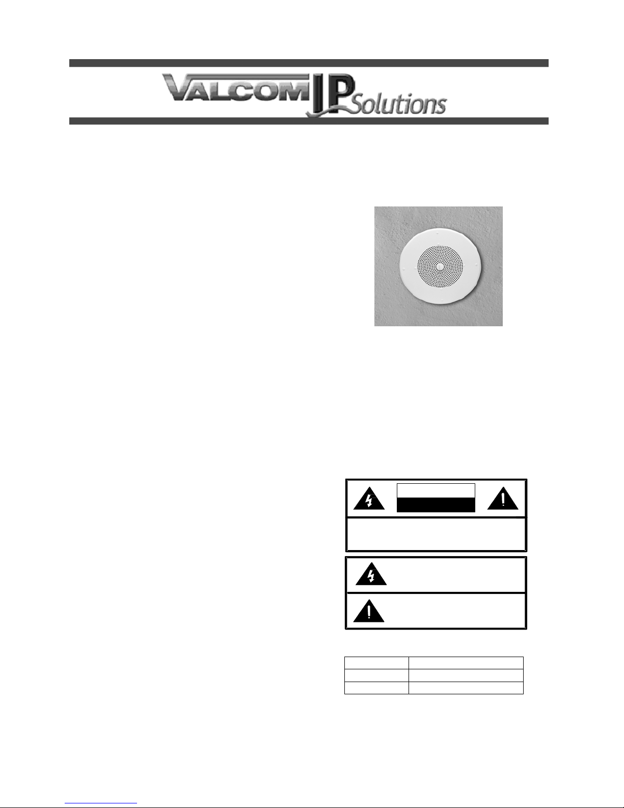
VIP-120
ONE-WAY IP CEILING SPEAKER
INTRODUCTION
The VIP-120 One-Way IP Ceiling Speaker enables
voice access to a single zone of one-way paging
over an IP-based LAN/WAN. This allows a page
zone extension anywhere on the network. The
speaker level is electrically adjusted during set up.
The enclosure is made of steel with a durable white
powder coated finish. Power is provided to the
VIP-120 via a Power over Ethernet switch meeting
the 802.3af specification.
SPECIFICATIONS
Access Methods
PBX, FXO Port w/VIP-811
POTS telephone set w/VIP-811
PBX, FXS Port w/VIP-821
Valcom M Cast Page Group
SIP – enabled telephone system
Features
RJ-45 network connection
Power over Ethernet (POE) 802.3af compatible
High Efficiency Class-D Amplifier
INSTALLATION
FCC Information
This equipment has been tested and found to
comply with the limits for a Class A digital device,
pursuant to Part 15 of the FCC Rules. These limits
are designed to provide reasonable protection
against harmful interference when the equipment is
operated in a commercial environment. This
equipment generates, uses and can radiate radio
frequency energy and if not installed and used in
accordance with the instruction manual, may cause
harmful interference to radio communications.
Operation of this equipment in a residential area
may cause harmful interference in which case the
user will be required to correct the interference at
his own expense.
DIMENSIONS/WEIGHT
13.00” Dia x 3.00” D
(33.02cm Dia. x 7.62cm D)
Weight: 2.5 lbs (1.13 kg)
Environment
Temperature: 0 to +40° C
Humidity: 0 to 85% non-precipitating
Precautionary Designations
CAUTION
RISK OF ELECTRIC SHOCK
DO NOT OPEN
CAUTION: To reduce the risk of electric shock,
Refer se rvic ing to qu alifie d serv ice pers onn e l.
Do not remove cover.
No user serviceable parts inside.
This symbol indicates that dangerous
voltage constituting a risk of electric
sho ck is pre s ent within this un it.
This symb o l indica tes that there are
imp o rtant op er ating a nd m a inte nance
instruction s in the lit erature accompanyin g
this unit.
Packing List
Qty. Item
1 VIP-120
1 VSP Document
1 947635
Page 2
MOUNTING
Cut an 8.50” diameter hole in ceiling tile. After
connections have been made to the speaker, attach
speaker to ceiling tile using the mounting hardware
provided. (A metal backbox with rails is available
separately as model V-9816M)
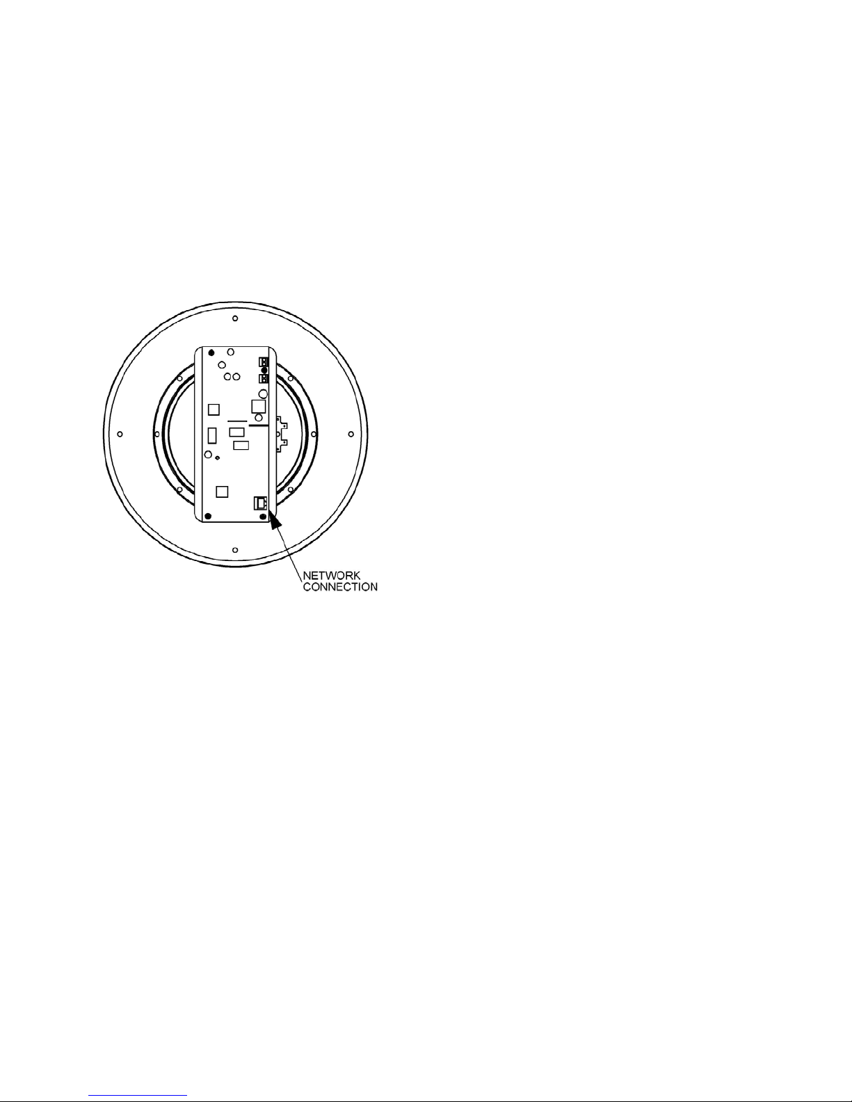
Network Connection
The VIP-120 has one RJ-45 network connector on
the rear panel. Use a standard Ethernet patch cable
to connect the VIP-120 to an Ethernet switch.
(See Figure 1).
Figure 1. VIP-120 Connections
Setup
Information specific to your application will need
to be programmed into the VIP-120 using a
computer. The PC used for programming should
be connected to the same subnet as the VIP-120.
Setup will be done using the IP Solutions Setup
Tool. Download the latest versio n of the free IP
Solutions Setup Tool from the Valcom web site at
www.valcom.com/vipsetuptool
TECHNICAL ASSISTANCE
When trouble is reported, verify power is being
supplied to the unit and there are no broken
connections. If a spare unit is available, substitute
a spare unit for the suspected defective unit.
Assistance in troubleshooting is available from the
factory. Call (540) 563-2000 and press 1 for
Technical Support or via email at
support@valcom.com
When requesting assistance, you should include all
available information. It is strongly suggested that
you go to the web site and review the information at
www.valcom.com.
Valcom equipment is not field repairable. Valcom,
Inc. maintains service facilities in Roanoke, VA.
Should repairs be necessary, attach a tag to the
unit clearly stating your company name, address,
phone number, contact person and the nature of
the problem. Send the unit to:
Valcom, Inc.
Repair & Return Dept.
5614 Hollins Road
Roanoke, Va. 24019-5056
2 947635
Page 3

Valcom, Inc. warrants its products only to the original purchaser, for its own use, to be free from defects in materials and workmanship under conditions of
normal use and service for a period of one year from the date of shipment. This Limited Warranty obligation shall be limited to the replacement, repair or
refund of any such defective device within the warranty period, provided that:
1. inspection by Valcom, Inc. indicates the validity of the claim;
2. the defect is not the result of damage, misuse or negligence after the original shipment;
3. the product has not been altered in any way or repaired by others and that factory sealed units are unopened (a service charge plus parts
and labor will be applied to units defaced or physically damaged);
4. freight charges for the return of products to Valcom are prepaid;
5. all units 'out of warranty' are subject to a service charge. The service charge will cover minor repairs (major repairs will be subject to
additional charges for parts and labor).
This Limited Warranty is in lieu of and excludes all other warranties, expressed or implied and in no event shall Valcom, Inc. be liable for any
anticipated profits, consequential damages, loss of time or other losses incurred by the buyer in connection with the purchase, operation,
maintenance, installation, removal or use of the product. The maximum liability of Valcom under this warranty is limited to the purchase price of the
specific Product covered by the warranty.
Disclaimer. Except for the Limited Warranty provided herein, the product is provided “as-is” without any warranty of any kind whatsoever including, without
limitation, any WARRANTY OF MERCHANTABILITY, FITNESS FOR A PARTICULAR PURPOSE OR NON-INFRINGEMENT.
This warranty specifically excludes damage incurred in shipment. In the event a product is received in damaged condition, the carrier should be notified
immediately. Claims for such damage should be filed with the carrier involved in accordance with the F.O.B. point.
VALCOM LIMITED WARRANTY
Headquarters:
Valcom, Inc.
5614 Hollins Road Roanoke, VA 24019-5056
Phone: (540) 563-2000 FAX: (540) 362-9800
3 947635
 Loading...