

Page 1

TECHNICAL MANUAL
VTM-07-007
OPERATION AND INSTALLATION
INSTRUCTIONS
AS-3226C/URC
VHF ANTENNA
Page 2
AS-3226C/URC VTM-07-007
REVISION SHEET
Revision Description Date
- - Original Issue - November 13, 2007
Errors in this publication can be reported to the Manufacturer.
Refer to Section 6 for contact information and address
175 Southgate Drive, P.O. Box 603, Guelph, Ontario, Canada N1H 6L3 Tel: 519-824-3220 Fax: 519-824-3411
Web Site: www.valcom-guelph.com
attention to the Engineering Department.
Valcom Manufacturing Group, Inc.
E-mail: enquiries@valcom-guelph.com
i
Valcom Manufacturing Group, Inc.
Page 3

AS-3226C/URC VTM-07-007
TABLE OF CONTENTS
Section
Page
1 GENERAL INFORMATION AND SAFETY PRECAUTIONS ............... 1
1-1 Safety Precautions ................................................ 1
1-2 Introduction ..................................................... 1
1-3 Equipment Description ............................................ 1
1-4 Relationship to Other Equipment .................................... 1
1-5 Reference Data .................................................. 1
1-6 Equipment and Documents Supplied ................................. 1
1-7 Equipment and Publications Required But Not Supplied .................. 1
2 OPERATION ........................................................ 5
2-1 General ........................................................ 5
3 FUNCTIONAL DESCRIPTION ......................................... 6
3-1 Functional Description .............................................. 6
a. Electrical Balance .......................................... 6
b. Radiation Patterns .......................................... 6
4 SCHEDULED MAINTENANCE ........................................ 7
4-1 Introduction ..................................................... 7
4-2 Scheduled Maintenance Action Index ................................ 7
4-3 Preventive Maintenance Procedures .................................. 7
4-4 Scheduled Performance Tests ....................................... 8
a. Safety Precautions .......................................... 8
b. Tools and Test Equipment ................................... 8
c. Title of Test ............................................... 8
d. Minimum Rating of Technician ............................... 8
e. VSWR Test Setup .......................................... 8
f. Procedures ................................................ 9
g. Test Values ............................................... 9
h. Corrective Actions ......................................... 9
5 TROUBLESHOOTING ............................................... 10
5-1 Introduction .................................................... 10
5-2 Troubleshooting Index ........................................... 10
5-3 Maintenance Turn-On Procedures .................................. 10
5-4 Troubleshooting Procedures ....................................... 10
6 CORRECTIVE MAINTENANCE ...................................... 12
ii
Valcom Manufacturing Group, Inc.
Page 4

AS-3226C/URC VTM-07-007
6-1 Introduction .................................................... 12
6-2 Adjustments and Alignment ....................................... 12
6-3 Repair ........................................................ 12
7 PARTS LIST ........................................................ 13
7-1 Introduction .................................................... 13
a. List of Parts ............................................. 13
b. List of Manufacturers ...................................... 13
8 INSTALLATION .................................................... 14
8-1 Site Information ................................................ 14
8-2 Tools and Materials Required ...................................... 14
8-3 Unpacking and Repacking ........................................ 14
8-4 Foundation .................................................... 14
8-5 Input Requirements .............................................. 14
8-6 Installation Procedures ........................................... 14
8-7 Installation Checkout ............................................ 14
LIST OF FIGURES
Figure Page
1-1 VHF Antenna AS-3226C/URC ...................................... 2
3-1 Balancing Transformer Arrangement ................................. 6
4-1 VSWR Test Setup ................................................ 9
8-1 Installation Data ................................................ 15
LIST OF TABLES
Table Page
1-1 Reference Data ........................................................ 3
1-2 Equipment and Documents Supplied ....................................... 3
1-3 Equipment and Publications Required But Not Supplied ........................ 4
1-4 Field and Factory Changes ............................................... 4
4-1 Scheduled Maintenance Action Index ...................................... 8
5-1 Troubleshooting Index ................................................. 10
5-2 Troubleshooting Procedures ............................................. 11
7-1 List of Parts .......................................................... 13
7-2 List of Manufacturers .................................................. 13
iii
Valcom Manufacturing Group, Inc.
Page 5

AS-3226C/URC VTM-07-007
SECTION 1
GENERAL INFORMATION AND SAFETY PRECAUTIONS
1-1. SAFETY PRECAUTIONS. When working in the vicinity of VHF Antenna AS-
3226C/URC, make sure the antenna is de-energized in accordance with the WARNING in
paragraphs 4-3 and 4-4, and when testing the antenna, make sure the test equipment is properly
grounded in accordance with WARNING in paragraph 4-4.
1-2. INTRODUCTION. This manual provides general information, operating and functional
descriptions, maintenance and troubleshooting instructions, parts list data, and installation data
for VHF Antenna AS-3226C/URC.
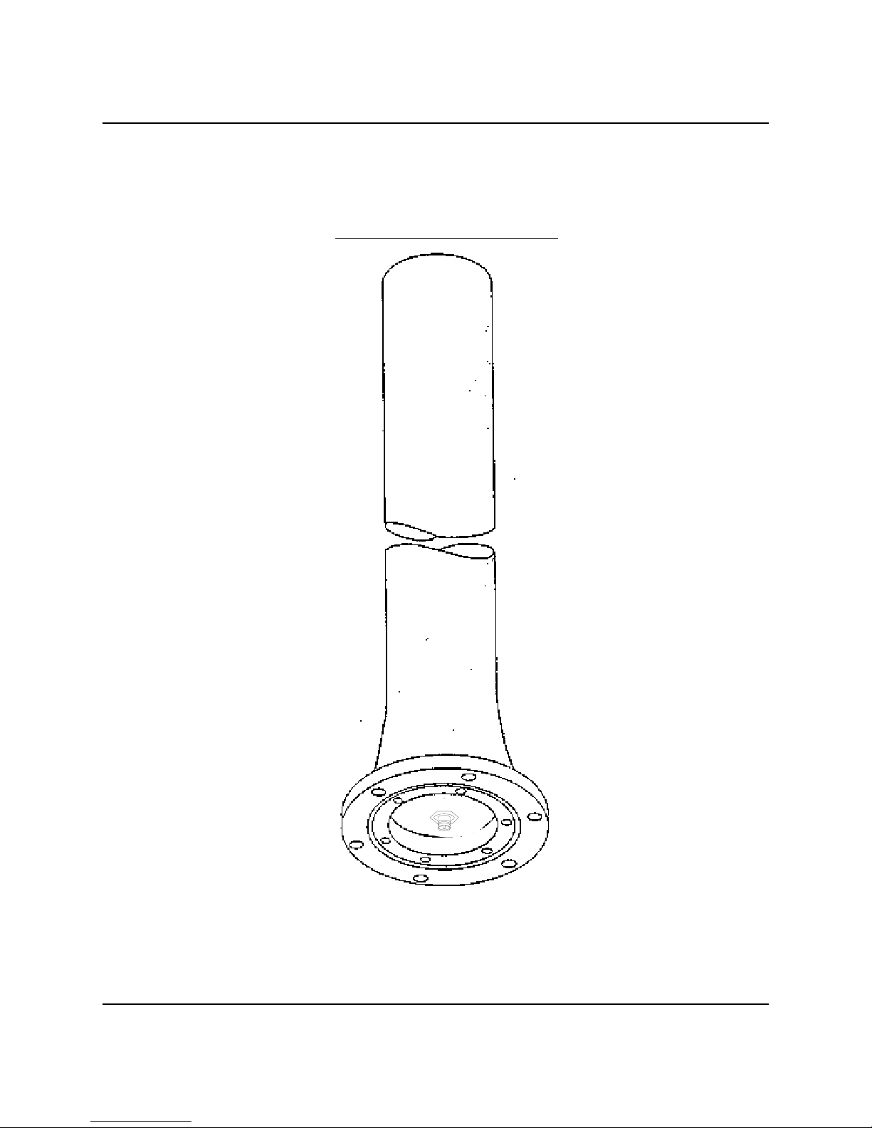
1-3. EQUIPMENT DESCRIPTION. The AS-3226C/URC VHF Antenna (see figure 1-1) is a
general purpose, high performance, reliable, vertically polarized, broadband dipole covering the
30 to 108 MHz frequency range. It is designed for use under the severe environmental conditions
encountered aboard naval vessels. It is used for either receiving or transmitting Very High
Frequency signals. The antenna is a base-mounted light-weight, single piece fiberglass vertical
dipole.
1-4. RELATIONSHIP TO OTHER EQUIPMENT. The AS-3226C/URC VHF Antenna
interfaces with the ship's VHF receiving and transmitting equipment.
1-5. REFERENCE DATA. Table 1-1 lists the reference data for the antenna.
1-6. EQUIPMENT AND DOCUMENTS SUPPLIED. Table 1-2 lists the equipment and
documents supplied.
1-7. EQUIPMENT AND PUBLICATIONS REQUIRED BUT NOT SUPPLIED. Table 1-3
lists the equipment and publications required but not supplied.
1
Valcom Manufacturing Group, Inc.
Page 6
AS-3226C/URC VTM-07-007
Figure 1-1 VHF Antenna AS-3226C/URC
2
Valcom Manufacturing Group, Inc.
Page 7

AS-3226C/URC VTM-07-007
Table 1-1. Reference Data
Parameter Specification
Nomenclature Antenna AS-3226CB/URC
Manufacturer Valcom Mgf Grp, Inc 35736
Frequency Range 30 to 108 MHz
Impedance 50 ohms
VSWR less than 3.0:1
Polarization Vertical
Power Capability 1000 watts
Gain 0 dBi (nominal)
Radiation Pattern Horizontal - omnidirectional
Vertical - figure 8
Temperature Operating: -54°C to +65°C
Non Operating: -62°C to +71°C
Wind Velocity 120 mph
Humidity 95%
Shock Qualified to meet MIL-S-901C, Grade A
Vibration Qualified to meet MIL-STD-167, Type I
Table 1-2. Equipment and Documents Supplied
Overall Dimensions (inches)
Qty Nomenclature
Crated Uncrated
Weight
Uncrated
Length Width (sq) Height Diameter
1
1
VHF Antenna AS3226C/URC
Technical Manual
VTM-07-00?
156 18 149 4.25 47 lbs
-- -- -- -- --
Table 1-3. Equipment and Publications Required But Not Supplied
3
Valcom Manufacturing Group, Inc.
Page 8

AS-3226C/URC VTM-07-007
Category
Power Supply
Modulating
Source
VHF Generator
Recommended
Equipment
General Radio
Type 1203-B
General Radio
Type 1214-A
General Radio
Type 1211-C and
Hewlett
Packard
Generator
Model 608E
Type 1215-C
Impedance
Bridge
Standing Wave
Indicator
Electronic
Counter
PRD Electronic
Type 3302
HP Model 415B
HP Type 5246L
--
General Radio
Type 1234
HP Type
5340A
Megohmmeter Freed Type 1620 --
Alternate
Test
Parameter
VSWR equal to
or less than 3.0:1
Insulation
Resistance
greater than 1
megohm
Application
Scheduled
maintenance
and troubleshooting
Troubleshooting
Table 1-4. Field and Factory Changes
Change Number Nomenclature Description
None -- --
4
Valcom Manufacturing Group, Inc.
Page 9

AS-3226C/URC VTM-07-007
SECTION 2
OPERATION
2-1. GENERAL. The AS-3226C/URC Antenna has no operating controls or indicators. It
operates only when the ship's VHF receiving and transmitting equipment is operated.
5
Valcom Manufacturing Group, Inc.
Page 10

AS-3226C/URC VTM-07-007
SECTION 3
FUNCTIONAL DESCRIPTION
3-1. FUNCTIONAL DESCRIPTION. The AS-3226C/URC VHF Antenna is a general
purpose, high performance, vertically polarized, broadband, balanced dipole covering the 30 to
108 MHz frequency range. It is used for either transmitting or receiving. The antenna is a
cylindrical dipole radiator fed by a conventional coaxial RF line. Integrated into the antenna
structure is a balancing transformer arrangement, which allows the dipole radiator to be fed in a
balanced manner eliminating extraneous line currents. (see figure 3-1).
a. Electrical Balance
. The electrical balance provided for the radiating elements permits
feeding the antenna directly by 50 ohm coaxial cable. The input VSWR is less than
3.0:1 on 50 ohms.
b. Radiation Patterns. Radiation patterns for the antenna correspond to those of a
balanced dipole in free space. Coverage in the plane perpendicular to the radiating
elements is omnidirectional. Figure 8 coverage, with nulls off the ends of the
elements, is provided in the plane of the radiators. The inherent broadband impedance
characteristics make the antenna relatively insensitive to its mounting environment
and minimize azimuth and zenith pattern distortion at any location.
Figure 3-1 Balancing Transformer Arrangement
6
Valcom Manufacturing Group, Inc.
Page 11

AS-3226C/URC VTM-07-007
SECTION 4
SCHEDULED MAINTENANCE
4-1. INTRODUCTION. This section provides preventative maintenance procedures and
scheduled performance tests to be accomplished on a regularly scheduled basis. These
procedures, performed as scheduled, will significantly reduce downtime for corrective
maintenance. The arrangement of the material in this section is a scheduled maintenance action
index with supporting test. The scheduled maintenance instructions in this manual are cancelled
when the Planned Maintenance System (PMS) is implemented for this equipment aboard your
ship or station.
4-2. SCHEDULED MAINTENANCE ACTION INDEX. Table 4-1 lists preventive
maintenance procedures and scheduled performance tests.
4-3. PREVENTATIVE MAINTENANCE PROCEDURES. The following procedures
included the information required for the antenna preventive maintenance:
WARNING
The antenna operates at 1000 watts. Ensure that the transmitting equipment
is de-energized prior to performing the preventive maintenance procedure.
b. Visually inspect the antenna for dirt. Wash dirt off the antenna with soap and water. A
technician with a minimum rating of ETN3 can perform the task.
b. Visually check painted surfaces for wear, chipping, etc. Paint the antenna with grey
epoxy enamel (MIL-P-24441). A technician with a minimum rating of ETN3 can
perform this task.
7
Valcom Manufacturing Group, Inc.
Page 12

AS-3226C/URC VTM-07-007
4-4. SCHEDULED PERFORMANCE TESTS. The following procedures include the
information required for checking the VSWR:
WARNING
The antenna operates at 1000 watts. Ensure that the transmitting equipment
is de-energized when performing the following test. Also make sure the test
equipment is grounded.
a. Safety Precautions. Be sure the transmitting equipment is deenergized and the test
equipment is properly grounded.
Table 4-1. Scheduled Maintenance Action Index
Periodicity Maintenance Action Reference
A Inspect antenna for dirt 4-3.a
A
Check painted surfaces for wear,
chipping, etc.
4-3.b
A Check the VSWR of the antenna 4-4
b. Tools and Test Equipment. No tools are required. The power supply, modulating
source, VHF generator, impedance bridge, standing wave indicator and electronic
counter in table 1-3 are used for this check.
c. Title of Test. The title of the test to be performed is VSWR Test.
d. Minimum Rating of Technician
. A technician with a minimum rating of ETN3 can
perform this task.
e. VSWR Test Setup. Figure 4-1 shows the VSWR test setup for the antenna.
8
Valcom Manufacturing Group, Inc.
Page 13

AS-3226C/URC VTM-07-007
f. Procedures.
(1) Prepare test setup as shown in figure 4-1.
(2) At 10 MHz intervals between 30 MHz and 100 MHz, inclusive, plus 108 MHz,
perform the following steps.
(a) Tune VHF generator to desired frequency as indicated on electronic counter.
(b) Tune impedance bridge for maximum reading as indicated on standing wave
indicator.
(c) Set reference level on standing wave indicator to 1.0 on SWR scale.
(d) Tune impedance bridge for minimum reading as indicated by standing wave
indicator.
(e) Read VSWR on standing wave indicator on SWR scale.
g. Test Values. If VSWR is 3.0:1 or greater, internal damage is indicated.
h. Corrective Action. Refer to table 5-3 for corrective actions.
Figure 4-1 VSWR Test Setup
9
Valcom Manufacturing Group, Inc.
Page 14

AS-3226C/URC VTM-07-007
SECTION 5
TROUBLESHOOTING
5-1. INTRODUCTION. Transmission trouble in the receiving or transmitting system of which
the AS-3226C/URC VHF Antenna is a part may be caused by trouble in the antenna, in another
piece of equipment, or in the transmission line. If trouble occurs, check to determine that the
equipment and the RF transmission line being used with the antenna are functioning properly
before attempting to follow the procedures described in this section. The antenna is essentially a
sealed assembly and as such is non repairable.
5-2. TROUBLESHOOTING INDEX. Table 5-1 lists possible troubles with references to the
appropriate procedures in this section.
5-3. MAINTENANCE TURN-ON PROCEDURE. The AS-3226C/URC VHF Antenna is
turned on when the ship's VHF receiving and transmitting equipment is turned on.
5-4. TROUBLESHOOTING PROCEDURES. Table 5-2 is a troubleshooting procedures
table.
Table 5-1. Troubleshooting Index
Functional
Area
Subnormal antenna
operation
Troubleshooting
Paragraph
5-4 -- 3-1 6-2
Troubleshooting
Diagram
Functional
Description
Paragraph
Alignment
Adjust
Paragraph
Table 5-2. Troubleshooting Procedures
10
Valcom Manufacturing Group, Inc.
Page 15

AS-3226C/URC VTM-07-007
SYMPTOM PROBABLE CAUSE CORRECTIVE ACTION
Low insulation resistance (less
than one megohm as indicated
by megohmmeter connected
between inner and outer
conductors of RF connector
High VSWR (greater than 3.0:1)
as indicated by VSWR test
described in paragraph 4-4.
1. Defective RF connector
or RF gasket.
Replace antenna.
2. Defective internal
assembly in antenna.
1. Defective RF connector
or RF gasket.
Replace antenna.
2. Defective internal
assembly in antenna.
11
Valcom Manufacturing Group, Inc.
Page 16

AS-3226C/URC VTM-07-007
SECTION 6
CORRECTIVE MAINTENANCE
6-1. INTRODUCTION. No corrective maintenance can be performed on the AS-3226C/URC
VHF Antenna.
6-2. ADJUSTMENTS AND ALIGNMENT. No adjustments and alignment are applicable to
the antenna.
6-3. REPAIR. No repair of the antenna or any of its parts is applicable.
12
Valcom Manufacturing Group, Inc.
Page 17

AS-3226C/URC VTM-07-007
SECTION 7
PARTS LIST
7-1. INTRODUCTION. The parts list for the antenna identifies all shipboard, tender, and
shore-based repair parts including attaching hardware. The parts list is arranged in two tables as
follows:
Table 7-1. List of Parts
Table 7-2. List of Manufacturers
a. List of Parts. Table 7-1 lists the parts of the AS-3226C/URC Antenna as shipped.
b. List of Manufacturers
Code for Manufacturers of the manufacturers supply items for the equipment as
referenced in Table 7-1.
UNIT NUMBER
1 VHF Antenna AS-3226C/URC 7-1
Valcom Manufacturing Group, Inc Code : 35736
Postal address: Shipping address:
Valcom Manufacturing Group, Inc
Guelph, Ontario
. Table 7-2 contains the name, address, and Federal Supply
Table 7-1. List of Major Units
Name of Unit Designation Page Number
Table 7-3. List of Manufacturers
P.O. Box 603
Canada
N1H 6L3
NOMENCLATURE
Valcom Manufacturing Group, Inc
175 Southgate Drive
Hanlon Industrial Park
Guelph, Ontario
Canada
N1G 3M5
13
Valcom Manufacturing Group, Inc.
Page 18

AS-3226C/URC VTM-07-007
SECTION 8
INSTALLATION
8-1. SITE INFORMATION. The AS-3226C/URC VHF Antenna is designed primarily for
shipboard installation. The antenna can also be used at shore installations. The antenna should be
installed in a non-obstructed environment, preferably more than 30 feet from any contiguous
structures, such as masts, bulkheads, or other metal objects.
8-2. TOOLS AND MATERIALS REQUIRED. No special tools and materials are required
for installation.
8-3. UNPACKING AND REPACKING. Table 1-2 gives data on the overall dimensions,
volume, and weight of the crated antenna. To unpack, carefully pry off the cover, and remove the
antenna from the container. Save the container to pack the antenna for reshipment. No special
handling procedures are required; observe normal precautions when handling the antenna.
8-4. FOUNDATION. The antenna should be installed vertically on a mounting plate that has
bolt holes matching those in the antenna base (see Figure 8-1). The mounting plate must have a
center hole to accommodate the transmission line to the antenna.
8-5. INPUT REQUIREMENTS. The antenna has an RF power handling capability of 1000
watts in the 30 to 108 MHz frequency range.
8-6. INSTALLATION PROCEDURES. After unpacking the antenna, proceed with its
installation as follows:
a. Examine the exterior of the antenna for damage; make sure that the RF connector is
not deformed, misaligned, or fractured.
b. Perform an insulation resistance test in accordance with step 1 of Table 5-2.
c. Check the voltage standing wave ratio in accordance with paragraph 4-4.
d. Place the antenna on its mounting plate. Tilt the antenna to connect the input cable to
the RF connector.
e. Secure the antenna to its mounting plate with six 1/2 in. bolts.
14
Valcom Manufacturing Group, Inc.
Page 19

AS-3226C/URC VTM-07-007
8-7. INSTALLATION CHECKOUT. Checkout of the antenna after installation can only be
accomplished by operating the ship's receiving and transmitting equipment that is used with the
antenna.
Figure 8-1 Installation Data of the AS-3226C/URC Antenna
15
Valcom Manufacturing Group, Inc.
 Loading...