

Valco baby HEATRITE ES Series, HEATRITE ES-60, HEATRITE ES-40, HEATRITE ES-80, HEATRITE ES-100 Installation, Operation & Service Manual
...Page 1

FOR YOUR SAFETY
WARNING
Installation must be done by a contractor qualified
in the installation and service of gas-fired heating
equipment or your gas supplier.
Improper installation, adjustment, alteration, service
or maintenance can result in death, injury or
property damage. Read the Installation, Operation
and Service Manual thoroughly before installing or
servicing this equipment.
If you smell gas:
1. Open windows.
2. DO NOT try to light any appliance.
3. DO NOT use electrical switches.
4. DO NOT use any telephone in
your building.
5. Extinguish any open flame.
6. Leave the building.
7. Immediately call your local gas
supplier after leaving the building.
Follow the gas supplier’s
instructions.
8. If you cannot reach your gas
supplier, call the Fire Department.
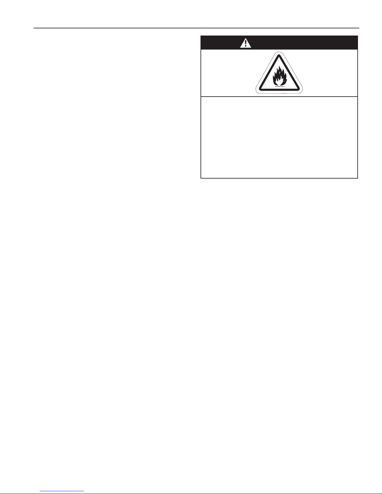
WARNING
Fire Hazard
Keep all flammable objects, liquids and
vapors the minimum required clearances to combustibles away from
heater.
Some objects will catch fire or explode
when placed close to heater.
Failure to follow these instructions can
result in death, injury or property
damage.
ES
Gas Fired, Low Intensity
Unitary Heater
Installation, Operation &
Service Manual
ES-40
ES-60
ES-80
ES-100
ES-125
ES-150
ES-175
© 2018 Roberts-Gordon LLC
Installer
Please take the time to read and understand
these instructions prior to any installation.
Installer must give a copy of this manual to the owner.
Owner
Keep this manual in a safe place in order to provide
your service technician with necessary information.
Val -Co
210 E. Main Street
P.O. Box 117
Coldwater, OH 45828 USA
Telephone: 800.998.2526
Fax: 419.678.2200
www.val-co.com
P/N VES36100NA Rev D 05/18
Page 2

Page 3
© 2018
Roberts-Gordon LLC
All rights reserved. No part of this work covered by the copyrights herein may be reproduced
or copied in any form or by any means - graphic, electronic, or mechanical, including
photocopying, recording, taping or information storage and retrieval systems - without the
written permission of Roberts-Gordon LLC.
TABLE OF CONTENTS
SECTION 1: Heater Safety...................................................... 1
1.1 Manpower Requirements ............................................. 1
1.2 Safety Labels and Their Placement ............................. 1
1.3 California Proposition 65 .............................................. 1
SECTION 2: Installer Responsibility ..................................... 4
2.1 Wall Tag ....................................................................... 4
2.2 Corrosive Chemicals.................................................... 4
2.3 National Standards and Applicable Codes .................. 4
SECTION 3: Clearances to Combustibles............................. 5
3.1 Required Clearances to Combustibles......................... 5
SECTION 4: National Standards and Applicable Codes .....8
4.1 Gas Codes................................................................... 8
4.2 Aircraft Hangars ........................................................... 8
4.3 Public Garages ............................................................8
4.4 Electrical ...................................................................... 8
4.5 Venting.........................................................................8
4.6 High Altitude ................................................................ 8
SECTION 5: Major Components ............................................9
5.1 Standard Parts List .................................................... 11
SECTION 6: Heater Installation............................................ 14
SECTION 7: Optional Heater Accessories..........................24
7.1 U-Tube Configuration..................................................24
7.2 Elbow Package Configuration..................................... 27
7.3 Reflector Side Extension ............................................29
7.4 Lower Clearance Shield Installation...........................30
SECTION 8: Venting..............................................................31
8.1 Venting.......................................................................31
8.2 Unvented Operation...................................................32
8.3 Horizontal Venting......................................................32
8.4 Vertical Venting..........................................................32
8.5 Unvented Operation Tube Termination ...................... 32
8.6 Length Requirements ................................................ 32
8.7 Vent Material Recommendations............................... 32
8.8 Horizontal Ventilation 4'' (10 cm) Pipe........................ 33
8.9 Vertical Ventilation 4'' (10 cm) Pipe............................33
8.10 Common Side Wall Venting ..................................... 34
8.11 Common Vertical Venting ........................................35
8.12 Outside Combustion Air Supply ...............................36
SECTION 9: Gas Piping........................................................39
SECTION 10: Wiring ..............................................................41
10.1 Line Voltage Thermostat Wiring...............................41
10.2 Low Voltage Thermostat with One Burner ............... 41
10.3 Low Voltage Thermostat Wiring with
ultiple Burners ....................................................... 42
M
10.4 Internal Wiring..........................................................43
10.5 Ladder Diagram ....................................................... 43
SECTION 11: Operation and Maintenance.......................... 44
11.1 Sequence of Operation ............................................ 44
11.2 To Shut Off Heater.................................................... 44
11.3 To Start Heater ......................................................... 44
11.4 Pre-Season Maintenance and Annual Inspection..... 44
11.5 Maintenance Checklist ............................................. 45
SECTION 12: Troubleshooting............................................. 47
12.1 Troubleshooting Flow Chart ..................................... 48
12.2 Manifold Gas Pressure Setting ................................ 50
SECTION 13: Replacement Parts ........................................ 51
SECTION 14: General Specifications .................................. 53
14.1 Material Specifications............................................. 53
14.2 Heater Specifications............................................... 53
14.3 Suspension Specifications....................................... 53
14.4 Controls Specifications ............................................ 53
Prin ted in U.S.A.
Page 4

Page 5

SECTION 1: HEATER SAFETY
SECTION 1: HEATER SAFETY
Your Safety is Important to Us!
This symbol is used throughout
the manual to notify you of
possible fire, electrical or burn
hazards. Please pay special
attention when reading and
following the warnings in these
sections.
Installation, service and annual inspection of heater
must be done by a contractor qualified in the
installation and service of gas-fired heating
equipment.
Read this manual carefully before installation,
operation or service of this equipment.
This heater is designed for heating nonresidential
indoor spaces. Do not install in residential spaces.
This heater is not certified to meet the requirements
of NFPA30A-2012 Section 7.6.6. (maximum tube
temperature of 750 °F (399 °C)). Do not install this
heater in facilities where compressed natural gas
(CNG) or liquid natural gas (LNG) are present. These
instructions, the layout drawing, local codes and
ordinances, and applicable standards that apply to
gas piping, electrical wiring, venting, etc. must be
thoroughly understood before proceeding with the
installation.
Protective gear is to be worn during installation,
operation and service in accordance to the
Occupational Safety and Hazard Administration
(OSHA). Gear must be in accordance to NFPA 70E,
latest revision when working with electrical
components. Thin sheet metal parts have sharp
edges. To prevent injury, the use of work gloves is
recommended. The use of gloves will also prevent
the transfer of body oils from the hands to the surface
of the reflector.
Before installation, check that local distribution
conditions, nature of gas and pressure, and
adjustment of the appliance are compatible.
This heater must be applied and operated under the
general concepts of reasonable use and installed
using best building practices.
This appliance is not intended for use by persons
(including children) with reduced physical, sensory or
mental capabilities, or lack of experience and
knowledge, unless they have been given supervision
or instr
uction concerning use of the appliance by a
person responsible for their safety. Children should
be supervised to ensure that they do no play with the
appliance.
For additional copies of the Installation, Operation
and Service Manual, please contact Val-Co.
1.1 Manpower Requirements
To prevent personal injury and damage to the heater,
two persons will be required for installation.
1.2 Safety Labels and Their Placement
Product safety signs or labels should be replaced by
the product user when they are no longer legible.
Please contact Val-Co or your VAL-CO independent
distributor to obtain replacement signs or labels. See
Page 2, Figure 1 through Page 3, Figure 2.
1.3 California Proposition 65
In accordance with California Proposition 65
requirements, a warning label must be placed in a
highly visible location on the outside of the
equipment (i.e., near equipment’s serial plate). See
label placement drawing on Page 3, Figure 2 for label
location. Avoid placing label on areas with extreme
heat, cold, corrosive chemicals or other elements. To
order additional labels, please contact Val-Co or your
VAL-CO independent distributor.
1 of 53
Page 6

ES-SERIES INSTALLATION, OPERATION AND SERVICE MANUAL
FIGURE 1: Top and Bottom Panel Label Placement
Description Part Number
Logo Label 91013205
Vent Length Label 91039500
Gas Connection Label 91018122
Burner Status Light Label 91033301
2 of 53
Page 7

FIGURE 2: Side and Back Panel Label Placement
SECTION 1: HEATER SAFETY
Description Part Number
Rating Plate Label 91010405
Lighting Instruction Plate Label 91029602
Wiring Label 91030308
Clearances to Combustibles Label 91013430
Proposition 65 Label 91070016
Thermostat Connection Label (not shown) 91037902
3 of 53
Page 8

ES-SERIES INSTALLATION, OPERATION AND SERVICE MANUAL
CAUTION
Product Damage Hazard
Do not use heater in area containing
corrosive chemicals.
Refer to appropriate Material Safety Data
Sheets (MSDS).
Failure to follow these instructions can result
in product damage.
SECTION 2: INSTALLER RESPONSIBILITY
The installer is responsible for the following:
• To install the heater, as well as the gas and
electrical supplies, in accordance with applicable
specifications and codes. Val-Co recommends
the installer contact a local Building Inspector or
Fire Marshal for guidance.
• To use the information given in a layout drawing
and in the manual together with the cited codes
and regulations to perform the installation.
• To install the heater in accordance with the
clearances to combustibles.
• To furnish all needed materials not furnished as
standard equipment.
• To plan location of supports.
• To provide access on all sides for burner servicing
and removal.
• To provide the owner with a copy of this
Installation, Operation and Service Manual.
• To never use heater as a support for a ladder or
other access equipment and never hang or
suspend anything from heater.
• To ensure there is adequate air circulation around
the heater and to supply air for combustion,
ventilation and distribution in accordance with
local codes.
• To safely and adequately install heater using
materials with a minimal working load of 75 lbs
(33 kg).
• To ensure the heater is placed in an approved
application.
2.1 Wall Tag
A laminated wall tag is available for the heater as
a permanent reminder of the safety instructions and
the importance of the required clearances to
combustibles. Please contact Val-Co or your VAL-CO
independent distributor to obtain the wall tag. Affix
the tag by peeling off the backing of the adhesive
strips on the rear surface and position the tag on a
wall near the
heater (e.g. thermostat or VAL-CO Controller).
A copy of the wall tag (P/N 91037912) is illustrated on
the back cover. For an immediate solution, you may
affix this copy on the wall near the heater.
Know your model number and installed configuration.
Model number and installed configuration are found on
the burner and in the Installation, Operation and
Service Manual. See Page 6, Figure 3 through Page
7, Figure 8. Write the proper clearance dimensions in
permanent ink according to your model number and
configuration in the open spaces on the tag.
2.2 Corrosive Chemicals
Val-Co cannot be responsible for ensuring that all
appropriate safety measures are undertaken prior to
installation; this is entirely the responsibility of the
installer. It is essential that the contractor, the subcontractor, or the owner identifies the presence of
combustible materials, corrosive chemicals or
halogenated hydrocarbons* anywhere in the
premises.
* Halogenated Hydrocarbons are a family of
chemical compounds characterized by the
presence of halogen elements (fluorine, chlorine,
bromine, etc.). These compounds are frequently
used in refrigerants, cleaning agents, solvents, etc.
If these compounds enter the air supply of the
burner, the life span of the heater components will
be greatly reduced. An outside air supply must be
provided to the burners whenever the presence of
these compounds is suspected. Warranty will be
invalid if the heater is exposed to halogenated
hydrocarbons.
2.3 National Standards and Applicable Codes
All appliances must be installed in accordance with
the latest revision of the applicable standards and
national codes. This refers also to the electric, gas
and venting installation. Note: Additional standards
for installations in public garages, aircraft hangars,
etc. may be applicable.
4 of 53
Page 9
SECTION 3: CLEARANCES TO COMBUSTIBLES
WARNING
Fire Hazard
Keep all flammable objects, liquids and
vapors the minimum required clearances to
combustibles away from heater.
Some objects will catch fire or explode when
placed close to heater.
Failure to follow these instructions can result
in death, injury or property damage.
3.1 Required Clearances to Combustibles
Clearances are the required distances that
combustible objects must be away from the heater to
prevent serious fire hazards. Combustibles are
materials that may catch on fire and include common
items such as wood, paper, rubber, fabric, etc.
Maintain clearances to combustibles at all times
for safety.
Clearances for all heater models are located on the
burner of the heater and on Page 6, Figure 3 through
Page 7, Figure 8 in this manual. Check the
clearances on each burner for the model heater
being installed to make sure the product is suitable
for your application and the clearances are
maintained. Read and follow the safety guidelines
below:
• Keep gasoline or other combustible materials
including flammable objects, liquids, dust or
vapors away from this heater or any other
appliance.
• The stated clearances to combustibles represents
a surface temperature of 90 °F (32 °C) above
room temperature. Building materials with a low
heat tolerance (s
canvas, tri-ply, etc) may be subject to degradation
at lower temperatures. It is the installer’s
responsibility to assure that adjacent materials
are protected from degradation.
• Maintain clearances from heat sensitive
equipment and workstations.
• Maintain clearances from vehicles parked below
the heater.
• Maintain clearances from swinging and overhead
doors, overhead cranes, vehicle lifts, partitions,
storage racks, hoists, building construction, etc.
• In locations used for the storage of combustible
materials, signs must be posted to specify the
maximum permissible stacking height to maintain
required clearances from the heater to the
combustibles. Signs must be posted adjacent to
the heater thermostat. In the absence of a
thermostat, signs must be posted in a
conspicuous location.
• Consult local Fire Marshal, Fire Insurance Carrier
or other authorities for approval of proposed
installation when there is a possibility of exposure
to combustible airborne materials or vapors.
• Hang heater in accordance to the minimum
suspension requ
uch as plastics, vinyl siding,
irements on Page 15, Figure 11.
SECTION 3: CLEARANCES TO COMBUSTIBLES
• If the radiant tubes must pass through the building
structure, be sure that adequate sleeving and fire
stop is installed to prevent scorching and/or fire
hazard.
5 of 53
Page 10

ES-SERIES INSTALLATION, OPERATION AND SERVICE MANUAL
NOTE: 1. All dimensions are from the surfaces of all tubes, couplings and elbows.
2. Clearances B, C and D can be reduced by 50% after 25' (7.5 m) of tubing downstream
from where the burner and burner tube connect.
FIGURE 3: LEVEL REFLECTOR
Model ABCDABCD
ES-40 6 27 53 27 16 69 135 69
ES-60 6 356335168916189
ES-80 6 38 66 38 16 97 168 97
ES-100 6 40 71 40 16 102 181 102
ES-125 6 46 77 46 16 117 196 117
ES-150 6 50 80 50 16 127 204 127
ES-175 8 52 82 52 21 133 209 133
FIGURE 4: LEVEL SIDE REFLECTOR
Model ABCDABCD
ES-40 6 9 53 44 16 23 135 112
ES-60 6 9 63 47 16 23 161 120
ES-80 6 9 70 54 16 23 178 138
ES-100 6 9 77 59 16 23 196 150
ES-125 6 9 83 65 16 23 211 166
ES-150 6 9 86 69 16 23 219 176
ES-175 8 9 88 73 21 23 224 186
(inches) (centimeters)
(inches) (centimeters)
FIGURE 5: TWO SIDE REFLECTORS
Model ABCDABCD
6 of 53
(inches) (centimeters)
ES-40 6 15 53 15 16 39 135 39
ES-60 6 23 66 23 16 59 168 59
ES-80 6 25 72 25 16 64 183 64
ES-100 6 27 78 27 16 69 199 69
ES-125 6 32 84 32 16 82 214 82
ES-150 6 35 88 35 16 89 224 89
ES-175 8 40 91 40 21 102 232 102
Page 11

NOTE: 1. All dimensions are from the surfaces of all tubes, couplings and elbows.
Radiant Tubes
Vent
Pipes
Unvented
Vented
A
E
F
2. Clearances B, C and D can be reduced by 50% after 25' (7.5 m) of tubing downstream
from where the burner and burner tube connect.
FIGURE 6: U-TUBE, LEVEL REFLECTOR
(inches) (centimeters)
Model ABCDABCD
ES-40
ES-60 6 35 63 30 16 89 161 77
ES-80 6 38 69 37 16 97 176 94
ES-100 6 40 76 39 16 102 194 100
ES-125 6 46 79 43 16 117 201 110
ES-150 6 50 84 47 16 127 214 120
ES-175 8 54 87 51 21 138 221 130
- UNAPPROVED -
FIGURE 7: 2-FOOT DECO GRILLE AND PROTECTIVE GRILLE
(inches) (centimeters)
Model ABCDABCD
ES-40 6 27 53 27 16 69 135 69
ES-60 6 35 63 35 16 89 161 89
ES-80 6 38 66 38 16 97 168 97
ES-100 6 40 71 40 16 102 181 102
ES-125 6 46 77 46 16 117 196 117
ES-150 6 50 80 50 16 127 204 127
ES-175 8 52 82 52 21 133 209 133
SECTION 3: CLEARANCES TO COMBUSTIBLES
- UNAPPROVED -
FIGURE 8: VENTING
(inches) (centimeters)
Model A E F A E F
ES-40 14 18 18 36 46 46
ES-60 141818364646
ES-80 20 24 18 51 61 46
ES-100 20 24 18 51 61 46
ES-125 20 24 18 51 61 46
ES-150 20 30 18 51 77 46
ES-175 20 30 18 51 77 46
7 of 53
Page 12

ES-SERIES INSTALLATION, OPERATION AND SERVICE MANUAL
SECTION 4: NATIONAL STANDARDS AND
APPLICABLE CODES
4.1 Gas Codes
Type of gas appearing on the nameplate must be
the type of gas used. Installation must comply
with national and local codes and requirements
of the local gas company.
United States: Refer to National Fuel Gas Code
NFPA 54/ANSI Z223.1 - latest revision.
Canada: Refer to Natural Gas and Propane
Installation Code CSA B149.1 - latest revision.
4.2 Aircraft Hangars
Installation in aircraft hangars must be in
accordance with the following codes:
United States: Refer to Standard for Aircraft
Hangars, NFPA 409 - latest revision.
Canada: Refer to Natural Gas and Propane
Installation Code CSA B149.1 - latest revision.
In aircraft storage and servicing areas, heaters
shall be installed at least 10' (3 m) above the
upper surface of wings or of engine enclosures
of the highest aircraft which may be housed in
the hangar. The measurement shall be made
from the wing or engine enclosure (whichever is
higher from the floor) to the bottom of the heater.
• In shops, offices and other sections of aircraft
hangars communicating with aircraft storage or
servicing areas, heaters shall be installed not
less than 8' (2.4 m) above the floor.
• Suspended or elevated heaters shall be so
located in all spaces of aircraft hangars that they
shall not be s
ubject to injury by aircraft, cranes,
movable scaffolding or other objects. Provisions
shall be made to assure accessibility to
suspended heaters for recurrent maintenance
purposes.
4.3 Public Garages
Installation in garages must be in accordance
with the following codes:
United States: Refer to Standard for Parking
Structures NFPA 88A - latest revision or the
Code for Motor Fuel Dispensing Facilities and
Repair Garages, NFPA 30A - latest revision.
Canada: Refer to Natural Gas and Propane
Installation Code CSA B149.1 - latest revision.
• Heaters must not be installed less than 8'
(2.4 m) above the floor. Minimum clearances to
combustibles must be maintained from vehicles
parked below the heater.
• When installed over hoists, minimum
clearances to combustibles must be maintained
from the upper most point of objects on the hoist.
4.4 Electrical
Heater must be electrically grounded in
accordance with the following codes:
United States: Refer to National Electrical Code
NFPA 70 - latest revision. Wiring must conform to
the most current National Electrical Code
®
, local
ordinances and any special diagrams furnished.
Canada: Refer to Canadian Electrical Code,
CSA C22.1 Part 1 - latest revision.
4.5 Venting
Venting must be installed in accordance with the
requirements within this manual and the
following codes:
United States: Refer to National Fuel Gas Code
NFPA 54/ANSI Z223.1 - latest revision.
Canada: Refer to Natural Gas and Propane
Installation Code CSA B149.1 - latest revision.
®
,
8 of 53
4.6 High Altitude
These heaters are approved for installations up
to 2000' (610 m) (US), 4500' (1370 m) (Canada)
without modification. Consult factory if US
installation is above 2000' (610 m) or Canadian
installation is above 4500' (1370 m).
Page 13

SECTION 5: MAJOR COMPONENTS
FIGURE 9: Major Component Descriptions - Standard Reflector
SECTION 5: MAJOR COMPONENTS
Burner with Tube
Gasket
Must be installed with
the flame observation
window facing down.
Burner Tube
Supplied in 10' (3 m) lengths.
Burner tube is always the first
tube after the burner.
Tube and Reflector Hanger
with Clamp Package
Position this hanger no more
than 4" (10 cm) away from the
burner.
Tube and Reflector Hanger
Suspend system from these
hangers.
Standard
Reflector
(Aluminum or
Stainless
Steel)
Alternate overlap as
shown on overview and on
Page 22, Figure 6.5.1.
Minimum overlap is 6" (16 cm).
Tube
Hot rolled or heat
treated aluminized tube
supplied in 10' (3 m) lengths.
Coupling Assembly
with Lock
Reflector End Cap
Punch out center
section to
accommodate tube.
Vent Adapter
Reflector Support Strap &
Wire Form
Flex Gas Line with
Shut Off Cock
Turbulator
Install turbulator
as specified in the
"Turbulator Installation" chart.
See Page 20, Step 6.4.
Turbulator is not required on the
ES-175.
9 of 53
Page 14

ES-SERIES INSTALLATION, OPERATION AND SERVICE MANUAL
FIGURE 10: Major Component Descriptions - High Efficiency Reflector
Burner with Tube
Gasket
Must be installed with
the flame observation
window facing down.
Burner Tube
Supplied in 10' (3 m) lengths.
Burner tube is always the first
tube after the burner.
Tube and Reflector Hanger
with Clamp Package-EF
Position this hanger no more
than 4" (10 cm) away from the
burner.
Tube and Reflector Hanger-EF
Suspend system from these
hangers.
High Efficiency Reflector
(Aluminum only)
Alternate
overlap as
shown on
overview
and
on Page 22, Step 6.5.1.
Minimum overlap is 6" (16 cm).
Tube
Hot rolled or heat
treated aluminized tube
supplied in 10' (3 m) lengths.
Coupling Assembly
with Lock
Reflector End Cap-EF
Punch out center
section to
accommodate tube.
Vent Adapter
Reflector Support Strap &
Wire Form
Flex Gas Line with
Shut Off Cock
10 of 53
Turbulator
Install turbulator
as specified in the
"Turbulator Installation" chart.
See Page 20, Step 6.4.
Turbulator is not required on the
ES-175.
Page 15

SECTION 5: MAJOR COMPONENTS
5.1 Standard Parts List
Table 1: Contents of the Burner Carton
Part No. Description ES-40 ES-60 ES-80 ES-100 ES-125 ES-150 ES-175
47481X Burner Assembly (Rate and Fuel Varies) 1 1 1 1 1 1 1
92700025 Gasket (Burner to Burner Tube) 1 1 1 1 1 1 1
VES36100NA Installation, Operation and Service Manual 1 1 1 1 1 1 1
92113900 Hex Head Nuts 5/16" - 18 Rolok 4 4 4 4 4 4 4
96411600 Split Lock washer 4 4 4 4 4 4 4
91201708 Pipe Nipple (Black) 1/2” NPT x 4” 1 1 1 1 1 1 1
91317300 1/4" Quick Disconnect (Wire) 2 2 2 2 2 2 2
*91412200 Flexible Stainless Steel Gas Hose - 1/2" NPT (US Models Only) 1 1 1 1 1
*91412204 Flexible Stainless Steel Gas Hose - 3/4" NPT (US Models Only) - - - - - 1 1
03051503 Turbulator Adapter 1 1 1 1 1 1 -
03051504 Turbulator Aluminized Steel 3 4 5 4 2 1 -
03051505 Turbulator Stainless Steel 1 - - - - - -
*Canadian Models: Rubber (Type 1) Gas Hoses available as an accessory.
See Page 39, Section 9
.
Table 2: Contents of Standard Core and Extension Packages
Core Packages Extension Packages
Aluminized Aluminized
Part No. Description
91409408
03051105
474833
Tube, HT Aluminized, 10
'
(3 m)
Burner Tube ST, ALUMI-THERM® Steel, 10' (3 m)
Burner Tube ST, HT ALUMI-THERM® Steel, 10' (3 m)
01312700 Coupling Assembly - 1 2 3 1234
02750303
Standard Reflector, 8
'
(3.5 m)
02750800End Cap 2222- - - -
03090101Tube and Reflector Hanger, Wide Pattern 23451234
91907302S-Hook 23451234
03050011 Reflector Support Package (Strap, Wire Form, Screws), Wide Pattern 12352346
91107720 U-Clip Package 11111111
03090101Vent Adapter 1111- - - -
01318901 Tube Clamp Package 1111- - - -
Part Number
10
'
20
'
30
'
40
'
10
'
20
'
30
(3m)
(6m)
(9m)
(12m)
(3m)
(6m)
(9m)
'
(12m)
-1231234
--11----
11------
23462346
40
'
474828
CPWST10ALUM
474829
472830
EXPW10ALUM
EXPW20ALUM
EXPW30ALUM
EXPW40ALUM
11 o f 5 3
Page 16

ES-SERIES INSTALLATION, OPERATION AND SERVICE MANUAL
Table 3: Contents of High Efficiency Core and Extension Packages
Part No. Description
91409408
Tube, HT Aluminized, 10' (3 m)
'
10
(3m)
-1231234
Core Packages Extension Packages
Aluminized Aluminized
20
'
30
'
40
'
10
'
20
'
30
(6m)
(9m)
(12m)
(3m)
(6m)
'
(9m)
40
(12m)
'
03051105
474833
Burner Tube ST, ALUMI-THERM® Steel, 10' (3 m)
Burner Tube ST, HT ALUMI-THERM® Steel, 10' (3 m)
--11----
11------
01312700 Coupling Assembly - 1 2 3 1 2 3 4
02750313
High Efficiency Reflector, 8
'
(3.5 m)
23462346
02750802 End Cap, High Efficiency 2 2 2 2 - - - -
03090102 Tube and Reflector Hanger, High Efficiency 2 3 4 5 1 2 3 4
91907302 S-Hook 2 3 4 5 1 2 3 4
03050012 Reflector Support Package (Strap, Wire Form, Screws) 1 2 3 5 2 3 4 6
91107720 U-Clip Package 1 1 1 1 1 1 1 1
90508701 Vent Adapter 1 1 1 1 - - - -
01318902 Tube Clamp Package - EF 1 1 1 1 - - - -
Part Number
EXP10ALUMEF
EXP20ALUMEF
CPST10ALUMEF
CPST20ALUMEF
CPST30ALUMEF
CPST40ALUMEF
EXP30ALUMEF
EXP40ALUMEF
12 of 53
Page 17

Table 4: Component Package Guide
Model
ES-40 10’ (3m) CPWST10ALUM
ES-60 20’ (6m) 474828
ES-80 20’ (6m) 474828
ES-100 30’ (9m) 474829
ES-125 40’ (12m) 474830
ES-150 50’ (15m) 474829 + EXPW20ALUM
ES-175 60’ (18m) 474829 + EXPW30ALUM
Table 5: Component Package Guide
Model
ES-40 10’ (3m) CPST10ALUMEF
SECTION 5: MAJOR COMPONENTS
Tubing Length Standard Core Packages-Wide Pattern
Minimum Aluminized
Tubing Length High Efficiency Core Packages
Minimum Aluminized
ES-60 20’ (6m) CPST20ALUMEF
ES-80 20’ (6m) CPST20ALUMEF
ES-100 30’ (9m) CPST30ALUMEF
ES-125 40’ (12m) CPST40ALUMEF
ES-150 50’ (15m) CPST30ALUMEF + EXP20ALUMEF
ES-175 60’ (18m) CPST30ALUMEF + EXP30ALUMEF
Although not recommended, additional tube lengths may be added to the heater. Tubing must be aluminized
(heat-treated or non-heat-treated), or porcelain coated. Additional tube lengths beyond the specified
minimum tubing length are considered vent pipe for length determination. Maximum vent length allowed is
45' (13.7 m) total.
13 of 53
Page 18

ES-SERIES INSTALLATION, OPERATION AND SERVICE MANUAL
WARNING
Cut/Pinch Hazard
Wear protective gear during installation,
operation and service.
Edges are sharp.
Failure to follow these instructions can result
in injury.
SECTION 6: HEATER INSTALLATION
WARNING
Severe Injury Hazard
Secure burner to burner tube with nuts and
lockwashers.
Hang heater with materials with a minimum
working load of 75 lbs (33 kg).
Failure to follow these instructions can result
in death, injury or property damage.
Expansion and contraction of the tube dictates that
the minimum suspension lengths must be
maintained. See table on Page 15, Figure 11.
To ensure your safety and comply with the terms of
the warranty, all units must be installed in
accordance with these instructions.
The gas or the electrical supply lines must not be
used to support the heater.
Do not locate the gas or electric supply lines directly
over the path of the flue products from the heater.
The heater must be installed in a location that it is
readily accessible for servicing.
The heaters must be installed in accordance with
clearances to combustibles as indicated on the rating
plate and in this instruction manual.
The minimum and maximum gas inlet pressures
must be maintained as indicated on the rating plate.
Typical installation configurations are shown on
Page 15, Figure 11.
14 of 53
Page 19

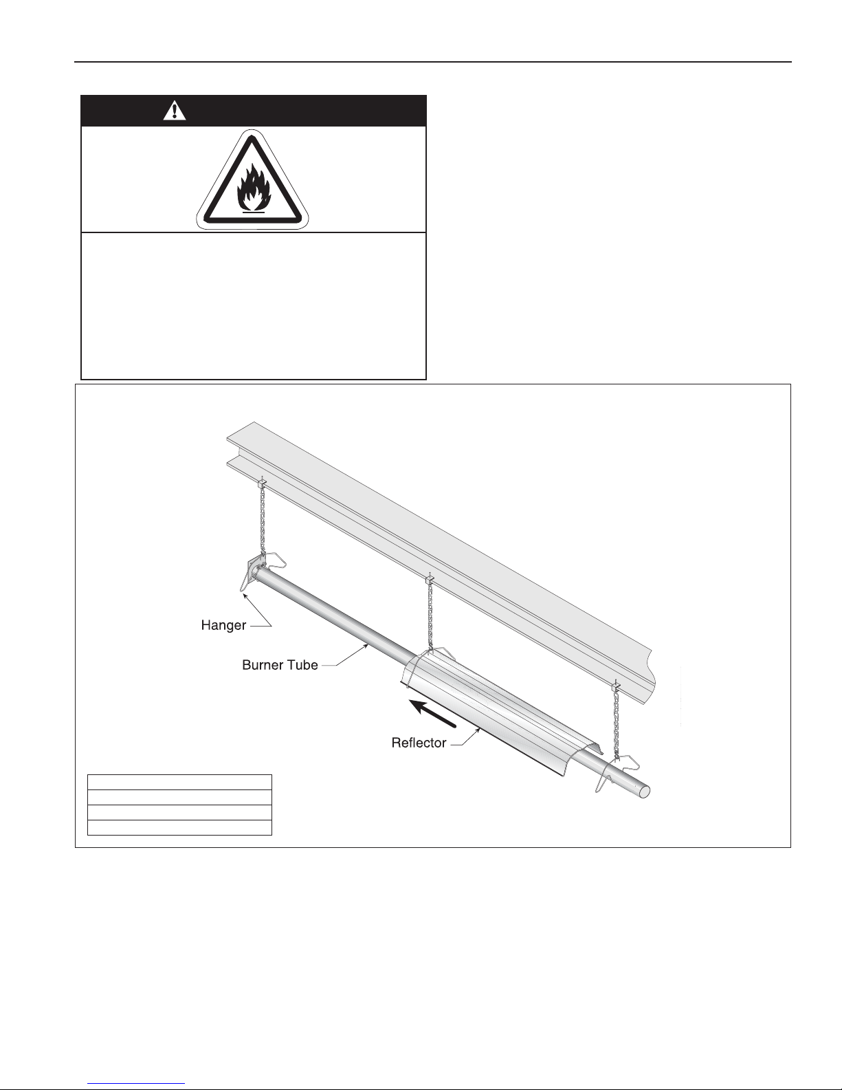
FIGURE 11: Critical Hanger Placement
SECTION 6: HEATER INSTALLATION
Description
S-Hook
Tube/Reflector Hanger
Run Length Typical Expansion Minimum “X” Length
10' (3 m) - 50' (15.2 m) ±1" (3 cm) 12" (30.5 cm)
51' (15.5 m) - 60' (18.3 m) ±2" (5 cm) 18" (45.7 cm)
61' (18.6 m) - 80' (24.4 m) ±3" (8 cm) 24" (61 cm)
15 of 53
Page 20

ES-SERIES INSTALLATION, OPERATION AND SERVICE MANUAL
FIGURE 12: Linear Heater Assembly Overview
16 of 53
Page 21

FIGURE 13: Linear Heater Layout Overview
SECTION 6: HEATER INSTALLATION
17 of 53
Page 22

ES-SERIES INSTALLATION, OPERATION AND SERVICE MANUAL
Step 6.1 Burner Tube Installation
Description
Burner Tube
S-Hook
Tube/Reflector Hanger
Step 6.2 Tube Clamp Package Installation
Description
Tube Clamp Package
18 of 53
Page 23

Step 6.3 Coupling and Tube Assembly
A
Close coupling and slide
opposite end into tab.
Position tab underneath
guide rail.
B
Insert wide end of slide bar/coupling lock into
guide rail on opposite end of tabs. Slide the slide
bar/coupling lock up the guide rail until snug
(approximately 3" (8 cm) to 4" (10 cm)).
C
Insert tubes into coupling
until end of each tube rests
against internal pins.
D
Strike slide bar/coupling lock with mallet or hammer
until tight.
Description
Coupling
Slide Bar/Coupling Lock
Tube
SECTION 6: HEATER INSTALLATION
Step 6.3.1 Coupling and Tube Assembly (Continued)
Tighten slide bar as shown below.
• Repeat Step 6.3 A - D until all tubes are assembled. See Page 20, Step 6.3.2.
19 of 53
Page 24

ES-SERIES INSTALLATION, OPERATION AND SERVICE MANUAL
7' 6" ± 1'
(2.3 m ± .25 m)
Step 6.3.2 Coupling and Tube Assembly (Continued)
10' ± 1'
(3 m ± .25 m)
Total Overall
Tube Length
Model
ES-40 10’ (3 m)
ES-60 20 (6 m)
ES-80 20' (6 m)
ES-100 30' (9 m)
ES-125 40' (12 m)
ES-150 50’ (15 m)
ES-175
Tub e Len gth
Mi nimum
Step 6.4 Turbulator Installation
Description
Turbulator Adapter 2.5' (76.2 cm)
Turbulator Section 2' (61 cm)
Turbulator Section 2.5' (76.2 cm) (Stainless)
Tube
Install turbulator as specified in the
“Turbulator Installation” chart below.
Turbulator is not required on the ES-125/150
Turbulator Installation
Model Tube Section
ES-40 1st 10' (3 m) Section
ES-60 2nd 10' (3 m) Section
ES-80 2nd 10' (3 m) Section
ES-100 3rd 10' (3 m) Section
ES-125 4th 10' (3 m) Section
ES-150 5th 10' (3 m) Section
ES-175 N/A
20 of 53
Page 25
Step 6.5 Reflector Installation
WARNING
Fire Hazard
Support reflector with reflector hanger
and support strap.
Reflector must not touch tube.
Failure to follow these instructions can result
in death, injury or property damage.
SECTION 6: HEATER INSTALLATION
Description
Tube/Reflector Hanger
Burner Tube
Reflector 96" (244 cm)
21 of 53
Page 26

ES-SERIES INSTALLATION, OPERATION AND SERVICE MANUAL
Step 6.5.1 Reflector, U-Clip and Reflector Support Installation
The pictorial drawings of the heater construction in
Section 6 are schematic only and provide a general
guideline of where hangers, reflector supports and
U-clips are to be installed.
To ensure proper expansion and contraction
movement of the reflectors, a combination of U-clips
reflector supports and U-clips depend on the
individual installation. Use either pop rivets or sheet
metal screws instead of u-clips when installing end
caps and joint pieces in areas where impact and high
wind may be a factor. The following rules must be
observed.
and reflector supports are used. The positioning of
1. Slide first reflector after burner a minimum 2” (4 cm) through first hanger and
ensure reflector end cap is securely fastened via U-clips, pop rivets, or sheet
metal screws. Position reflector support with tight screws in middle of first
reflector.
Description
Reflector Support Package
Wire Form
Reflector Support Strap, Wide Pattern
Screw #8 x 3/4"
U-Clip Package
Reflector End Cap
22 of 53
NOTE: High efficiency
reflectors should NOT
be used in applications
exposed to wind.
Page 27

Step 6.6 Burner Installation
SECTION 6: HEATER INSTALLATION
Description
Burner
Lock Washer
Nut
Gasket
NOTE: To ensure proper orientation,
attached burner tube with tube weld
facing downward
23 of 53
Page 28

ES-SERIES INSTALLATION, OPERATION AND SERVICE MANUAL
WARNING
Cut/Pinch Hazard
Wear protective gear during installation,
operation and service.
Edges are sharp.
Failure to follow these instructions can result
in injury.
SECTION 7: OPTIONAL HEATER ACCESSORIES
7.1 U-Tube Configuration
Heaters (except ES-40) are approved for optional Utube configurations.
The U-tube may be installed in a standard horizontal
position. When using a U-tube configuration, the
following additional rules must be adhered to:
• A minimum of 10' (3 m) on ES-60/80 and a
'
minimum of 15
required between the burner and the U-tube.
• The correct turbulator (See Page 20, Step 6.4)
must be installed in the last standard section of
the tube.
• The burner must never be operated in a tilted
position.
• The heater must be properly supported at all
locations. See Page 27, Figure 7.2.
(4.5 m) on ES-100/125/150/175 is
24 of 53
Page 29

FIGURE 14: U-Tube Heater Assembly Overview
Secure overlap
with six #8
sheet metal screws.
Reflector Junctions
SECTION 7: OPTIONAL HEATER ACCESSORIES
FIGURE 15: U-tube reflector kit (optional)
Description
Kit, U-tube reflector kit
Reflector Joints
25 of 53
Page 30

ES-SERIES INSTALLATION, OPERATION AND SERVICE MANUAL
FIGURE 16: U-Tube Heater Layout Overview
a = 14” (36 cm)
Reflector Width (Not Shown)
b = 2” (5 cm)
End Cap to Burner
c = 2” (5 cm)
End Cap Hanger
d = 7’ 6” (2.3 cm)
Distance Between First and
Second Hangers
e = 10’ (3.0 m)
Distance Between Next Hangers
f = 5’ (1.5 m)
Distance Between Last Full Tube
Hanger and Half Tube Hanger
g = 11.5” (29.2 cm) Burner Length
h = 8” (21.6 cm) Burner Height
* Requires the last reflector
before the u-tube to be cut in
half for use on both sides.
** Requires the last tube before
the u-tube to be cut in half for
use on both sides.
26 of 53
Page 31

7.2 Elbow Package Configuration
Step 7.2.1 Elbow Installation
Description
Elbow Package
90° Elbow
Coupling
Reflector End Cap
Reflector Joint Piece
U-Clip Package
Step 7.2.2 Elbow Installation
SECTION 7: OPTIONAL HEATER ACCESSORIES
Minimum Distance Required
Between Burner and Elbow
Model
ES-40 N/A
ES-60 10' (3 m)
ES-80 10' (3 m)
ES-100 15' (4.5 m)
ES-125 15' (4.5 m)
ES-150 15' (4.5 m)
ES-175 15' (4.5 m)
Minimum
Distance
Step 7.2.3 Reflector Joint Installation
27 of 53
Page 32

ES-SERIES INSTALLATION, OPERATION AND SERVICE MANUAL
Step 7.2.4 Reflector Joint Installation
Step 7.2.5 Reflector Joint Detail
FIGURE 17: Reflector Joint Detail
28 of 53
Page 33

7.3 Reflector Side Extension
Step 7.3.1 Bracket Installation
Description
Reflector Side Extension Package
Reflector Side Extension
96" (244 cm)
Retainer Clips
Sheet Metal Screws
SECTION 7: OPTIONAL HEATER ACCESSORIES
Order Separately
Reflector Side Extension Bracket
Step 7.3.2 Side Reflector Installation
29 of 53
Page 34

ES-SERIES INSTALLATION, OPERATION AND SERVICE MANUAL
Lower Clearance Shield
17"
(43 cm)
Washers
Screws
Locknuts
7.4 Lower Clearance Shield Installation
Step 7.4.1 Shield Support Strap Assembly
12"
(30 cm)
Align Pilot Holes
Reflector
Description
Lower Clearance Shield Package
Shield Support Strap
Lower Clearance Shield 8' (2.4 m)
Locknut #8
Flat Washer #8
Screw #8 x 3/8''
30 of 53
Page 35

SECTION 8: VENTING
WARNING
Carbon Monoxide Hazard
Heaters installed unvented must be interlocked
with sufficient building exhaust.
Heaters must be installed according to the
installation manual.
Failure to follow these instructions can result
in death or injury.
WARNING
Cut/Pinch Hazard
Wear protective gear during installation,
operation and service.
Edges are sharp.
Failure to follow these instructions can result
in injury.
SECTION 8: VENTING
Any portion of vent pipe passing through a
combustible wall must have an approved thimble
to conform with the above listed codes.
Vent pipe must be sloped downward away from the
heater 1/2'' (1 cm) for every 20' (6 m).
The heater may be individually vented or common
vented. When venting horizontally, a maximum of
two heaters can be commonly vented. See Page 34,
Section 8.10. When venting vertically, a maximum of
four heaters can be commonly vented. See Page 35,
Section 8.11.
The heater may also be installed unvented in certain
circumstances according to building ventilation
codes. Refer to the above codes and Page 32,
Section 8.2 for further information. Unvented
operation also requires compliance with the
clearances to combustibles given on Page 7, Figure
8.
8.1 Venting
This heater must be vented in accordance with the
rules contained in this manual and with the following
national codes and any state, provincial or local
codes which may apply:
United States: Refer to National Fuel Gas Code
NFPA 54/ANSI Z223.1 - latest revision.
Canada: Refer to Natural Gas and Propane
Installation Code CSA B149.1 - latest revision.
Exhaust end of heater will accept a 4'' (10 cm) vent
pipe using the vent adapter. To prevent leakage of
condensation, install the vent adapter with the seam
on top and seal the joint using a high temperature
silicone sealant.
The bottom of the vent or air intake terminal shall not
be located less than 1' (0.3 m) above grade level.
The vent shall not terminate less than 7' (2.1 m)
above grade where located adjacent to public
walkways.
Vent terminal must be installed at a height sufficient
to prevent blockage by snow, and building materials
protected from degradation by flue gases.
Secure all joints with #8 x 3/8 sheet metal screws.
Seal all joints with high temperature silicone sealant.
Vent terminal must be beyond any combustible
overhang.
8.1.1 United States Requirements
Vent must terminate at least 3' (0.9 m) above any
forced air inlet located within 10' (3.1 m).
Vent must terminate at least 4' (1.2 m) below, 4'
(1.2 m) horizontally from, or 1' (0.3 m) above any
door, operable window, or gravity air inlet into any
building.
8.1.2 Canadian Requirements
The vent shall not terminate within 6' (1.8 m) of a
mechanical air supply inlet to any building.
The vent shall not terminate within 3' (0.9 m) of a
window or door that can be opened in any building,
any non-mechanical air supply inlet to any building,
or of the combustion air inlet of any other appliance.
31 of 53
Page 36

ES-SERIES INSTALLATION, OPERATION AND SERVICE MANUAL
8.2 Unvented Operation
Sufficient ventilation must be provided in the amount
of 4 cfm per 1000 Btu/h firing rate (United States); 3
cfm per 1000 Btu/h firing rate (Canada).
Use of optional outside combustion air is not
recommended with unvented heaters.
If exhaust fans are used to supply ventilation air, an
interlock switch must be used to prevent the heater
from coming on when the fans are off. This may be
done using a pressure switch.
8.3 Horizontal Venting
In noncombustible walls only, vent terminal may be
used.
For 4" (10 cm) vents in either combustible or
noncombustible walls, use Tjernlund VH1-4 or
equivalent, insulated vent terminal. Follow the
manufacturer's instructions for proper
installation.
For 6" (15 cm) common vents in either combustible
or noncombustible walls, use Tjernlund VH1-6 or
equivalent, insulated vent terminal. Follow the
manufacturer's instructions for proper installation.
8.4 Vertical Venting
For 4'' (10 cm) common vent, an approved vent cap
must be used.
For 6'' (15 cm) common vent, an approved vent cap
must be used.
For common vertical venting of more than two
heaters, See Page 35, Section 8.11.
8.6 Length Requirements
The maximum vent length allowed is 45' (13.7 m).
The maximum outside air supply duct length allowed
is 45' (13.7 m).
The total vent length, plus outside air duct length,
plus any extensions to minimum heat exchanger
lengths, cannot exceed 65' (19.8 m).
Vent length should be limited to less than 20' (6 m).
If using vent lengths greater than 20' (6 m),
condensation will form in the vent pipe. Insulation
and additional sealing measures (high temperature
silicone at all seams) are required. Optional heat
exchanger beyond minimum lengths is considered
as vent length for length determination.
Subtract 15' (4.6 m) of maximum allowed vent or
duct length per vent elbow if more than two are
used.
8.7 Vent Material Recommendations
Vent recommendations:
1. Porcelain coated tubing 4'' (10 cm) O.D.
2. Heat treated aluminized tubing 4'' (10 cm) O.D.
Heat treated aluminized tubing 6'' (15 cm) O.D.
3. Single wall flue pipe - minimum 26 ga.
(Supplied by others)
NOTE: 4" (10 cm) O.D. Porcelain coated tubing, 4"
(10 cm) O.D. Heat treated aluminized tubing, and 6"
(15 cm) O.D. Heat treated aluminized tubing are
equivalent to single wall flue pipe.
A vent shall not extend less than 2' (0.6m) above the
highest point where it passes through a flat roof of a
building.
8.5 Unvented Operation Tube Termination
Turndown type vent terminal with a screen must be
installed at the exhaust end of the tube. Vent
terminal design shall not incorporate backdraft flap.
FIGURE 18: Tube Termination
32 of 53
Page 37

8.8 Horizontal Ventilation 4'' (10 cm) Pipe
4" (10 cm)
Single Wall Pipe
Vent Adapter
Vent Terminal
Combustible or
Non-Combustible Wall
Vent Adapter
18" (46 cm)
Min.
Vent Terminal
4" (10 cm) Single Wall Pipe
Non-Combustible Wall Only
SIDE VIEW
Description
Vent Terminal (Comb. Wall)
Vent Terminal
8.9 Vertical Ventilation 4'' (10 cm) Pipe
SECTION 8: VENTING
Description
Vent Cap 4" (10 cm)
33 of 53
Page 38

ES-SERIES INSTALLATION, OPERATION AND SERVICE MANUAL
8.10 Common Side Wall Venting
Description
Vent Terminal 6" (15 cm)
Requirements:
• Maximum of two heaters can be commonly
vented through a side wall.
• Heaters must be of the same BTU output.
• Heaters must be controlled by a common
thermostat.
34 of 53
Page 39

8.11 Common Vertical Venting
SECTION 8: VENTING
Requirements:
• Maximum of four heaters can be commonly
vented through the roof.
• Heaters must be of the same BTU output.
• Heaters must be controlled by a common
thermostat.
• Connections to a common stack must be
positioned to avoid direct opposition between
streams of combustion gases.
35 of 53
Page 40

ES-SERIES INSTALLATION, OPERATION AND SERVICE MANUAL
8.12 Outside Combustion Air Supply
IMPORTANT: If the building has a slight negative
8.12.1 Length Requirements
Follow the constraints listed on Page 32, Section 8.6.
pressure or corrosive contaminants, such as
halogenated hydrocarbons, are present in the air, an
outside combustion air supply to the heater is
required. Seal all combustion air pipe joints.
Use of optional outside combustion air is not
recommended with unvented heaters.
The air supply duct may have to be insulated to
prevent condensation on the outer surface. The
outside air terminal must not be more than 1' (31 cm)
above the vent termination while maintaining a
minimum distance of 3' (93 cm) for both vertical and
horizontal venting.
8.12.2 Vertical Outside Air Supply for Single Heater Installation
Description
Vent Cap 4" (10 cm)
36 of 53
Page 41

8.12.3 Horizontal Outside Air Supply for Single Heater Installation
Band Clamp
(Recommended)
Flex Hose
(Recommended)
Vent Cap
Wall
Burner
4" (10 cm)
Single Wall Pipe
Description
Vent Cap 4" (10 cm)
SECTION 8: VENTING
8.12.4 Vertical Outside Air with Outside Air Inlet Kit
Description Part Number
Outside Air Inlet Kit 4" 90502401
Bird Screen 01365400
Hose Clamp - 4" 93901300
Vent Pip - 4" OD 90507200
Flange - 4" 90507001
Flexible Vent Pipe - 4" OD 91409603
Screw #12 Hex hd (Self tap) 13404
Description Part Number
Outside Air Inlet Kit 5" 90502403
Bird Screen 01397400
Hose Clamp - 5" 90901301
Vent Pip - 5" OD 90507201
Flange - 5" 90507002
Flexible Vent Pipe - 5" OD 91409604
Screw #12 Hex hd (Self tap) 13404
37 of 53
Page 42

ES-SERIES INSTALLATION, OPERATION AND SERVICE MANUAL
8.12.5 Vertical Outside Air Supply for Double Heater Installation
Description
Vent Cap 6" (15 cm)
Requirements:
• Heaters must be controlled by a common thermostat.
8.12.6 Horizontal Outside Air Supply for Double Heater Installation
Description
Vent Cap
6" (15 cm)
30
Requirements:
• Heaters must be controlled by a common thermostat.
38 of 53
Page 43

SECTION 9: GAS PIPING
WARNING
Fire Hazard
Tighten gas hose fittings to connect gas
supply according to Figure 23.
Gas hose can crack when twisted.
Gas hose moves during normal operation.
Use only 36" (91 cm) long connector of 1/2" or
3/4" nominal ID.
Connector supplied with heater for U.S.
models (not with Canadian models).
Failure to follow these instructions can result
in death, injury or property damage.
WARNING
Explosion Hazard
Leak test all components of gas piping
before operation.
Gas can leak if piping is not installed
properly.
Do not high pressure test gas piping with
heater connected.
Failure to follow these instructions can result
in death, injury or property damage.
SECTION 9: GAS PIPING Install the gas hose as shown on Page 40, Figure 19.
The gas hose accommodates expansion of the
heating system and allows for easy installation and
service of the burner. Before connecting the burners
to the supply system, verify that all high pressure
testing of the gas piping has been completed.
There is an expansion of the tube with each firing
cycle; this will cause the burner to move with respect
to the gas hose. This can cause a gas leak resulting
in an unsafe condition if the gas connection is not
made strictly in accordance with Figure 19 on Page
40.
Meter and service must be large enough to handle all
the burners being installed plus any other connected
load. The gas hose which feeds the system must be
large enough to supply the required gas with a
maximum pressure drop of 1/2" w.c. When gas piping
is not included in the layout drawing, the local gas
supplier will usually help in planning the gas piping.
Gas lines must meet applicable codes:
United States: The Flexible Stainless Steel Gas
Hose (US models) supplied with the heater is certified per the Standard for Connectors for Gas Appliances, ANSI Z21.24/CSA 6.10 - latest revision.
Canada: The Rubber Type 1 Gas Hose (Canadian
models) optional with the heater is certified as being
in compliance with the Standard for Elastomeric
Composite Hose and Hose Couplings for Conducting
Propane and Natural Gas, CAN/CGA 8.1 - Latest
revision.
• Check the pipe and tubing ends for leaks
before placing heating equipment into
service. When checking for gas leaks, use a
soap and water solution; never use an open
flame.
39 of 53
Page 44

ES-SERIES INSTALLATION, OPERATION AND SERVICE MANUAL
FIGURE 19: Gas Connection with Flexible Gas Hose
See Page 53, Section 14
Description
High gas pressure regulator ½” – 2 PSI
High gas pressure regulator ¾” – 5 PSI
Description
1/2" Flexible Stainless Steel Gas Hose (US Models)
3/4" Flexible Stainless Steel Gas Hose (US Models)
1/2" Rubber Type 1 Gas Hose (Canadian Models)
3/4" Rubber Type 1 Gas Hose (Canadian Models)
40 of 53
Page 45

SECTION 10: WIRING
DANGER
Electrical Shock Hazard
Disconnect electric before service.
Heater must be properly earthed.
Failure to follow these instructions can result
in death or electrical shock.
Line Voltage
Thermostat
Gnd.
Gnd.
120 V-60 Hz
Supply Circuit
HN HN
Gnd.
L1
L2
T
Low Voltage
Terminal Detail
On All Burners
10.1 Line Voltage Thermostat Wiring
SECTION 10: WIRING
Heaters can be controlled using several methods.
Normally thermostats are used to control the heaters
but they can also be controlled by an energy
management system. Section 10.1 illustrates the
connection for heaters controlled by a line voltage
thermostat.
For heaters on a low voltage thermostat, See Page
41, Section 10.1. Heaters must be grounded in
accordance with applicable codes: United States:
®
Refer to National Electrical Code
NFPA 70 - latest
revision; Canada: Refer to Canadian Electrical Code
CSA C22.1 Part I - latest revision.
If any of the original internal wiring must be replaced,
it must be replaced with wiring materials having a
temperature rating of at least 105 °C and 600 volts.
10.2 Low Voltage Thermostat with One Burner
120 V-60 Hz
Supply Circuit
L1
L2
Gnd.
Low Voltage
Thermostat
T
HN
Gnd.
Low Voltage
Terminal Detail
41 of 53
Page 46
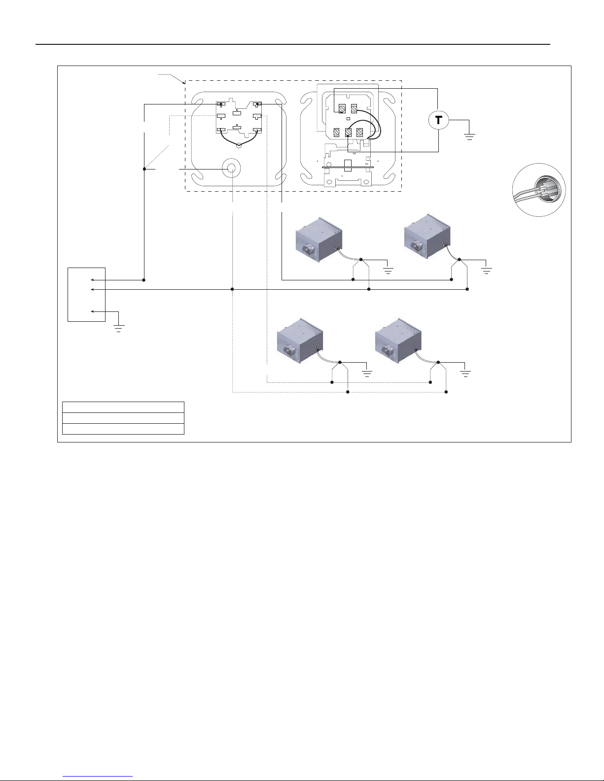
ES-SERIES INSTALLATION, OPERATION AND SERVICE MANUAL
NH
Gnd.
NH
Gnd.
L1
L2
Gnd.
120V-60 Hz
supply circuit
Low Voltage Thermostat
RC
W
G
Y
1
2
3
4
5
6
COIL COIL
Black
Black
White Red
Transformer Relay
FRONT VIEW BACK VIEW
Burner 1 Burner 2
NH
Gnd.
Burner 3
NH
Gnd.
Burner 4
Purple
Red/Yellow
When using 1-2 burners, use SPST
Transformer Relay.
When using 3-4 burners, use DPDT
Transformer Relay.
Low Voltage
Terminal Detail
on all Burners
10.3 Low Voltage Thermostat Wiring with Multiple Burners
Description
Thermostat Relay-SPST
Transformer Relay-DPDT
42 of 53
Page 47

10.4 Internal Wiring
SECTION 10: WIRING
BLK
MOTOR/BLOWER
BLK
BLK
VALVE
10.5 Ladder Diagram
POWER SUPPLY
120V 60 HZ
GAS
BLUE
R1
BLUE
PRESSURE SWITCH
TH
C1
V1
C2
S1
V2
GND
IGNITION
MODULE
PLUG
1
3
TERMINAL
BUSHING
YEL
5
4
NUETRAL
BLK
(L2)
GRN
YEL
BLUE
THERMOSTAT
TO
R1
BLK
GRN
GRN
WHT
YEL
WHT
YEL
BURNER ON LED
FLAME SENSE
IGNITER
LINE
(L1)
1
3
TRANSFORMER
BRN
120VAC
GND
L2
L1
BLK
TRANSFORMER
24V
THERMOSTAT
PRESSURE
SWITCH
GAP
ELECTRODE
R1
BLOWER
GAS VALVE
120VAC
24VAC
RELAY
TH
S1
SPARK
C2
R1
V2
BURNER ON
43 of 53
Page 48

ES-SERIES INSTALLATION, OPERATION AND SERVICE MANUAL
SECTION 11: OPERATION AND MAINTENANCE
DANGER
Electrical Shock Hazard
Disconnect electric
before service.
Heater must be
connected to a properly
grounded electrical
source.
Failure to follow these instructions can result in death, electric shock, injury or property damage.
This heater is equipped with a direct spark ignition
system.
11.1 Sequence of Operation
4. Turn the thermostat up. When the thermostat
calls for heat, the blower motor will energize.
5. When the motor approaches nominal running
RPM, the pressure switch closes and activates
the ignition module.
6. After a 45 second prepurge, the ignition module
then opens the gas valve and energizes the
spark igniter.
7. When the flame is established, the sparking
sequence ceases.
Explosion Hazard
Turn off gas supply to
heater before service.
WARNING
Burn Hazard
Allow heater to cool
before service.
Tubing may still be hot
after operation.
11. When thermostat is satisfied, all power to the
unit is shut off.
11.2 To Shut Off Heater
Set thermostat to lowest setting.
Turn OFF electric power to heater.
Turn OFF manual gas valve in the heater supply line.
11.3 To Start Heater
Turn gas valve and electric power OFF and wait five
minutes for unburned gases to vent from heater.
Turn ON main gas valve.
Turn ON electric power.
Set thermostat to desired temperature.
Burner should light automatically.
Cut/Pinch Hazard
Wear protective gear
during installation,
operation and service.
Edges are sharp.
8. If the flame is not established during the ignition
sequence, the ignition module closes the gas
valve and purge begins. Module will try 2
additional times for ignition (with purges in
between trials). If ignition is not established, the
module will lockout.
9. If the flame extinguishes during operation, the
ignition module will attempt the multiple trial
sequence described in step 5. If ignition is not
re-established, the module w
hour or until reset.
10.After lockout, the control can be reset by turning
down thermostat for five seconds, and then
raising it again to desired temperature, or by
disconnecting power and then reconnecting.
overall heater condition should be thoroughly inspected.
44 of 53
ill lockout for one
11.4 Pre-Season Maintenance and Annual
Inspection
To ensure yo
operation of the heating system, service and annual
inspections must be done by a contractor qualified in
the installation and service of gas-fired heating
equipment.
Turn off gas and electric supplies before performing
service or maintenance. Allow heater to cool before
servicing.
Before every heating season, a contractor qualified in
the installation and service of gas-fired heating
equipment must perform a thorough safety
inspection of the heater.
For best performance, the gas, electrical, thermostat
connections, tubing, venting, suspensions and
ur safety and years of trouble-free
Page 49

SECTION 11: OPERATION AND MAINTENANCE
NOTE: Gas flow and burner ignition are among the
first things that should be throughly inspected.
Please see Page 45, Section 11.5 for suggested
items to inspect.
set forth in the VAL-CO manuals and all applicable
governmental authorities pertaining to the
installation, service, operation and labeling of the
equipment.
To help facilitate optimum performance and safety,
11.5 Maintenance Checklist
Installation Code and Annual Inspections:
All installation and service of VAL-CO equipment
must be performed by a contractor qualified in the
installation and service of equipment sold and
Val-Co recommends that a qualified contractor
conduct, at a minimum, annual inspections of your
VAL-CO equipment and perform service where
necessary, using only replacement parts sold and
supplied by Val-Co.
supplied by Val-Co and conform to all requirements
The Vicinity of the Heater Do not store or use flammable objects, liquids or vapors near the heater.
Immediately remove these items if they are present.
See Page 5, Section 3.
Vehicles and Other
Objects
Maintain the clearances to combustibles.
Do not hang anything from, or place anything on, the heater.
Make sure nothing is lodged underneath the reflector, in between the tubes or
in the decorative or protective grilles (included with select models).
Immediately remove objects in violation of the clearances to combustibles.
See Page 5, Section 3.
Reflector Support reflector with reflector hanger and support strap.
Reflector must not touch tube.
Make sure there is no dirt, sagging, cracking or distortion.
Do not operate if there is sagging, cracking or distortion.
Make sure reflectors are correctly overlapped. See Page 22, Section 6.5.1.
Clean outside surface with a damp cloth.
Vent Pipe Venting must be intact. Using a flashlight, look for obstructions, cracks on the
pipe, gaps in the sealed areas or corrosion.
The area must be free of dirt and dust.
Remove any carbon deposits or scale using a wire brush.
See Page 31, Section 8.
Outside Air Inlet Inlet must be intact. Look for obstructions, cracks on the pipe, gaps in the
sealed areas or corrosion.
The area must be free of dirt and dust. Clean and reinstall as required.
Tubes Make sure there are no cracks.
Make s
ure tubes are connected and suspended securely.
See Page 14, Section 6.
Make sure there is no sagging, bending or distortion.
Clean or replace as required.
Gas Line Check for gas leaks. See Page 39, Section 9.
Burner Observation
Window
Blower Scroll, Wheel and
Make sure it is clean and free of cracks or holes.
Clean and replace as required.
Compressed air or a vacuum cleaner may be used to clean dust and dirt.
Motor
45 of 53
Page 50

ES-SERIES INSTALLATION, OPERATION AND SERVICE MANUAL
Burner Cup and Orifice Clear of obstructions (even spider webs will cause problems).
Carefully remove any dust and debris from the burner.
Electrode Replace if there are cracked ceramics, excessive carbon residue, or erosion
of the electrode.
The electrode gap should be 1/8" (3.2 mm).
Thermostat There should be no exposed wire or damage to the thermostat.
See Page 41, Section 10.
Suspension Points Make sure the heater is hanging securely. Look for signs of wear on the chain
or ceiling.
See Page 15, Figure 11.
Lower Clearance Shield
(optional)
The lower shield must be securely attached. Inspect shield support straps
and lower clearance shield anchor points.
See Page 30, Section 7.4.
Make sure shield is installed correctly and secured in place if necessary.
See Page 30, Section 7.4.
Wall Tag If wall tag is present, make sure it is legible and accurate. Please contact Val-
Co or your VAL-CO independent distributor, if you need a wall tag. See Page
4, Section 2.1
Safety Labels Product safety signs or labels shou
ld be replaced by the product user when
they are no longer legible. Please contact Val-Co or your VAL-CO independent distributor to obtain replacement signs or labels. See Page 2, Figure 1
through Page 3, Figure 2.
46 of 53
Page 51

SECTION 12: TROUBLESHOOTING
Fire Hazard
Keep all flammable
objects, liquids and
vapors the minimum
required clearances to
combustibles away
from heater.
Some objects will catch
fire or explode when
placed close to heater.
Cut/Pinch Hazard
Wear protective gear
during installation,
operation and service.
Edges are sharp.
WARNING
Failure to follow these instructions can result in death, injury or property damage.
Burn Hazard
Allow heater to cool
before service.
Tubing may still be hot
after operation.
Explosion Hazard
Turn off gas supply to
heater before service.
DANGER
Electrical Shock Hazard
Disconnect electric before service.
Heater must be properly earthed.
Failure to follow these instructions can result
in death or electrical shock.
SECTION 12: TROUBLESHOOTING
47 of 53
Page 52

ES-SERIES INSTALLATION, OPERATION AND SERVICE MANUAL
Module Diagnostic Codes:
LED Problem Solution
4 second steady
flash at start of cycle Normal Wait for valve to open
Steady on Microprocessor failure Replace module
within module
Three flashes Ignition lockout Recycle unit: check for
Lockout of module spark and valve opening and
after 3 tries replace:if none, replace module
12.1 Troubleshooting Flow Chart
48 of 53
Page 53

SECTION 12: TROUBLESHOOTING
49 of 53
Page 54
ES-SERIES INSTALLATION, OPERATION AND SERVICE MANUAL
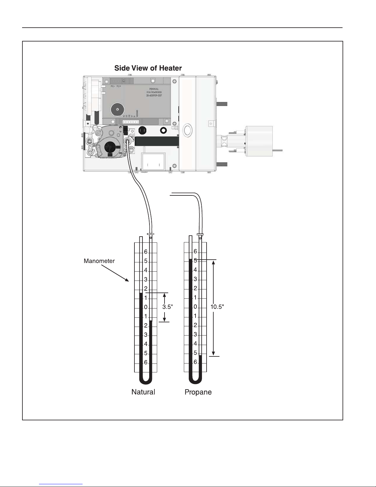
12.2 Manifold Gas Pressure Setting
50 of 53
Page 55

SECTION 13: REPLACEMENT PARTS
Carbon Monoxide Hazard
WARNING
Use only genuine ROBERTS GORDON® replacement parts per this installation, operation and
service manual.
Failure to follow these instructions can result in death, electric shock, injury or property damage.
Explosion Hazard
DANGER
Electrical Shock Hazard
Fire Hazard
SECTION 13: REPLACEMENT PARTS
See warnings and important information before removing or replacing parts. After any maintenance or repair
work, always test fire the heater in accordance with the start-up instructions on Page 44, Section 11 to help
ensure all safety systems are in working order before leaving the heater to operate. Minor faults may be
traced by using the troubleshooting charts on Page 47, Section 12 through Page 50, Figure 12.2.
51 of 53
Page 56

ES-SERIES INSTALLATION, OPERATION AND SERVICE MANUAL
FIGURE 20: Burner Exploded View
2
3
12
4
6
11
5
Description
1 Gas Valve (Natural)
1 Gas Valve (LP)
Tube Gasket (Not Shown)
Blower Inlet Gasket (Not Shown)
2 Motor and Blower Assembly
Air Adapter Collar (Not Shown)
3 Burner Cup Assembly
4 Igniter
5 Mica Window Assembly
6Flame Sensor
7 Transformer
8 Thermostat Connection
9 Jumper Wire
10 Pressure Switch:
(80, 100, 125, 150, 175)
(40)
(60)
LED Burner Status Light (Not Shown)
11 24 Vac Relay
12 DSI Ignition Module
8
9
10
7
1
Val-Co Part Number
474834
474835
474820
03050900
90708600-P
91911700
474828
474822
02553203
90439300
90436900K
91317900
03090900
90439803K
90439807K
90439805K
474826
474836
474094
52 of 53
Page 57

SECTION 14: GENERAL SPECIFICATIONS
8.5
(21.6 cm)
12
(30.7)
11.5
(29.2 cm)
14.1 Material Specifications
14.1.1 Reflectors
.024 Aluminum
(Optional .024 Stainless Steel Type 304)
14.2 Heater Specifications
14.2.1 Ignition
Fully automatic, three-try, direct spark, electronic
14.3 Suspension Specifications
Hang heater with materials with a minimum working
load of 75 lbs (33 kg). See Page 15, Figure 11.
14.4 Controls Specifications
Time switches, thermostats, etc. can be wired into
the electrical supply. External controls supplied as an
optional extra.
ignition control, 100% safety shut-off.
General Specifications for ES-Series heaters are as follows:
Heat Input Rate Length “A”
Model (Btu/h) x (1000) Minimum Space Spot
ES-40 40 10' (3 m) 8'-10' (2.4-3 m) 8' (2.4 m)
ES-60 65 20' (6 m) 10'-12' (3-3.6 m) 9' (2.7 m)
ES-80 80 20' (6 m) 12-15' (3.6 - 4.5 m) 11' (3.3 m)
ES-100 100 30' (9 m) 12-15' (3.6 - 4.5 m) 12' (3.7 m)
ES-125 125 40' (12 m) 15-20' (4.5 - 6 m) 15' (4.6 m)
ES-150 150 50' (15 m) 20-25' (6 - 7.6 m) 20' (6.1 m)
ES-175 175 60' (18 m) 25' (7.6 m) 23' (7 m)
*See Page 5, Section 3 for clearances to combustibles.
GAS PRESSURE AT MANIFOLD:
Natural Gas: 3.5" wc
LP Gas: 10.5" wc
PIPE CONNECTION:
1/2" NPT (for ES-40, 60, 80, 100 & 125)
3/4" NPT (for ES-150 and 175)
DIMENSIONS:
Vent Connection Size: 4" (10 cm)
Outside Air Connection Size: 4" (10 cm)
Refer to figure above for dimensional information.
Recommended
Minimum Mounting Height*
GAS INLET PRESSURE:
Natural Gas:
for ES-40, 60, 80, 100, 125, 150 4.6" wc Minimum
for ES-175 5.0" wc Minimum
14.0" wc Maximum
LP Gas: 11.0" w c M i ni m um
14.0" wc Maximum
ELECTRICAL RATING (ALL MODELS):
120 V - 60 Hz, 1 A (run)
Page 58

Page 59

Page 60

 Loading...