

Page 1
VAL AVIONICS LTD
COM 2000
VHF Transceiver
Installation and Operator’s
Manual
Revision 3
March 2013
P/N 172200-3
Page 2

I N S T A L L A T I O N A N D O P E R A T O R ’ S M A N U A L
C O M 2 0 0 0 – V H F T R A N S C E I V E R
V A L A V I O N I C S L T D
Revision History:
October 2010 – Initial Printing
May 2012 – Inserted section 1.4: FCC regarding FCC ID and emissions.
December 2012 – Updated Appendix A, table 4 with serial pin port. Spelling Corrections
March 2013 – Updated Appendix A for units with serial number 20720 to current.
Revision 3 Page 2 of 31
March 2013
Page 3

I N S T A L L A T I O N A N D O P E R A T O R ’ S M A N U A L
C O M 2 0 0 0 – V H F T R A N S C E I V E R
V A L A V I O N I C S L T D
Table of Contents
1
2
3
4
5
6
7
8
Table 1: Specifications .................................................................................................................................. 6
Table 2: Equipment Supplied ........................................................................................................................ 7
Table 3: Equipment Not Supplied ................................................................................................................. 7
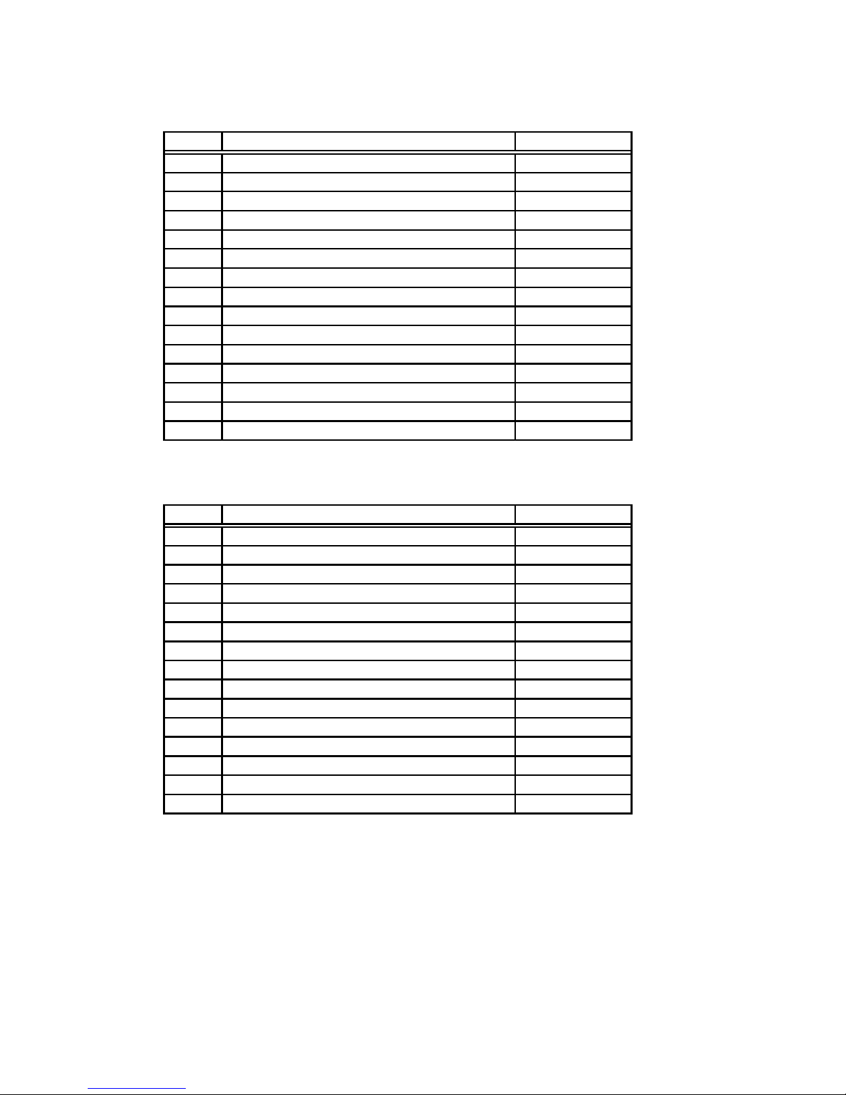
Table 4: Rear Connector Pin Functions ....................................................................................................... 17
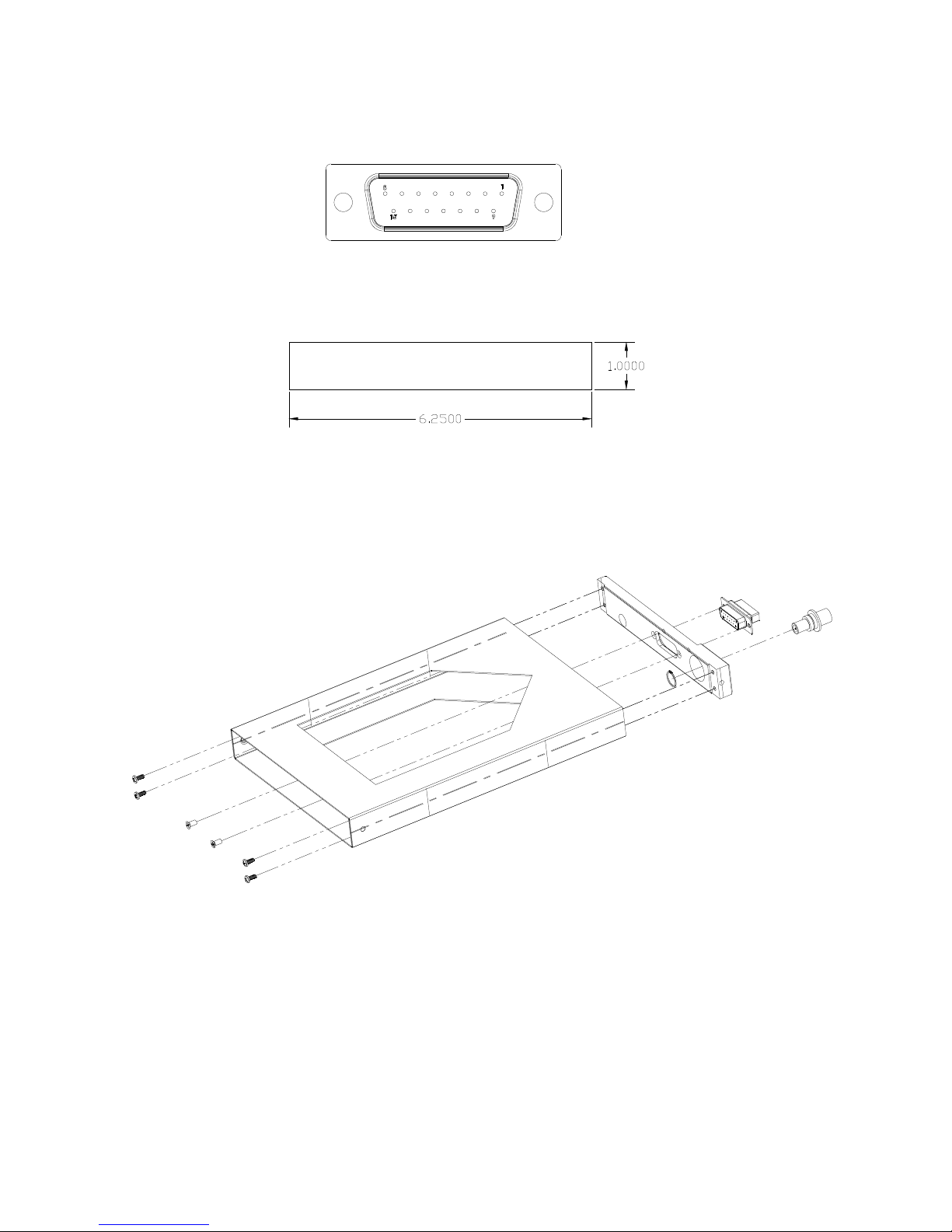
Figure 1: Unit Controls ................................................................................................................................ 11
Figure 2: Physical Dimensions .................................................................................................................... 16
Figure 3: P1 Connector Pin Out................................................................................................................... 16
Figure 4: Panel Cut Out ............................................................................................................................... 16
Figure 5: Mounting Tray Assembly Exploded View................................................................................... 16
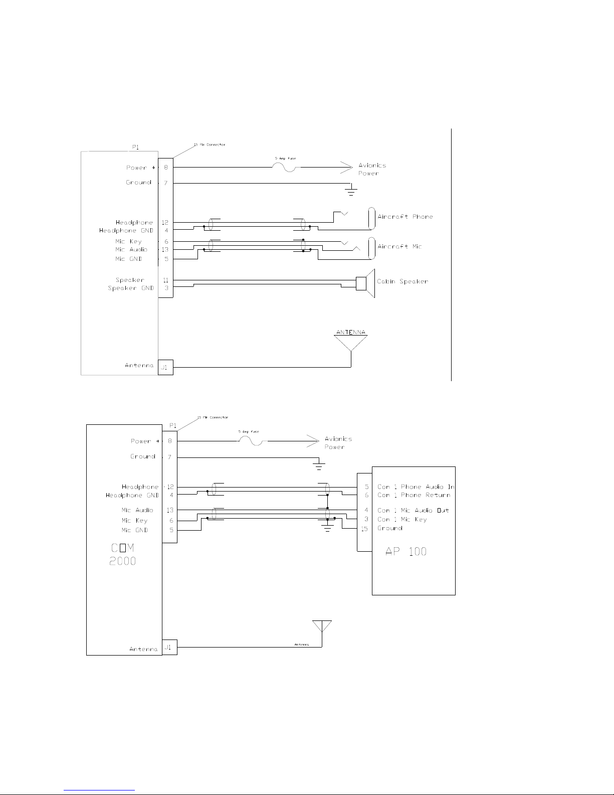
Figure 6: COM 2000 Basic Wiring Diagram................................................................................................ 18
Figure 7: Interface with AP100 .................................................................................................................... 18
SECTION I - GENERAL INFORMATION 4
1.1 INTRODUCTION...........................................................................................................................................4
1.2 SCOPE ............................................................................................................................................................4
1.3 EQUIPMENT DESCRIPTION.......................................................................................................................4
1.4 FCC Emission Band ........................................................................................................................................5
1.5 SPECIFICATIONS .........................................................................................................................................6
1.6 EQUIPMENT SUPPLIED ..............................................................................................................................7
1.7 EQUIPMENT REQUIRED BUT NOT SUPPLIED .......................................................................................7
1.8 LICENSE REQUIREMENTS.........................................................................................................................7
SECTION II - INSTALLATION 8
2.1 GENERAL INFORMATION .........................................................................................................................8
2.1.1 Scope .....................................................................................................................................................8
2.2 UNPACKING AND INSPECTION................................................................................................................8
2.3 EQUIPMENT INSTALLATION PROCEDURES .........................................................................................8
2.3.1 Cooling Requirements ...........................................................................................................................8
2.3.2 Mounting Requirements ........................................................................................................................8
2.3.3 Wire Harness Fabrication ......................................................................................................................9
2.3.4 COM 2000 Installation ..........................................................................................................................9
2.4 POST INSTALLATION CHECK...................................................................................................................9
2.4.1 Operational Check ...............................................................................................................................10
2.4.2 Final Inspection ...................................................................................................................................10
2.5 LIMITATIONS .............................................................................................................................................10
SECTION III - OPERATION 11
3.1 GENERAL INFORMATION .......................................................................................................................11
3.1.1 Scope ...................................................................................................................................................11
3.1.2 Display Functions ................................................................................................................................11
3.1.3 User Controls .......................................................................................................................................11
3.2 System Configuration....................................................................................................................................13
3.2.1 Accessing Setup Functions ..................................................................................................................13
SECTION IV - WARRANTY AND SERVICE 14
4.1 LIMITED WARRANTY ..............................................................................................................................14
4.2 SERVICE ......................................................................................................................................................14
Appendix A – INSTALLATION DRAWINGS AND CONNECTOR LAYOUT 15
Appendix B – WIRING DIAGRAMS 18
Appendix C – Certifications 19
7.1 TSO Certification: .........................................................................................................................................19
Appendix D – INSTRUCTIONS FOR CONTINUED AIRWORTHINESS 20
8.1 MAINTENANCE INSTRUCTIONS ............................................................................................................20
Revision 3 Page 3 of 31
March 2013
Page 4

I N S T A L L A T I O N A N D O P E R A T O R ’ S M A N U A L
C O M 2 0 0 0 – V H F T R A N S C E I V E R
V A L A V I O N I C S L T D
1 SECTION I - GENERAL INFORMATION
1.1 INTRODUCTION
Thank you for purchasing our COM 2000 – VHF Transceiver. Here at Val Avionics Ltd., our core design
philosophy is based on the ease of installation and use. The COM 2000 represents 20 years of refinement in that
process, based on the feedback of customers that have used the COM 760. The COM 2000 takes the original idea of
the COM 760: a simple to use, reliable, and without the frills of other radios; Overhauled and incorporating new
and exciting features.
That design philosophy translates into the ease of installation and simple operation makes the COM 2000 – VHF
Transceiver a communication solution for a wide variety of aircraft panels, from the Homebuilt through heavy
twins. The COM 2000 satisfies the need for compact, fully intergraded, quality radio that can be counted on to
provide years of reliable service.
Before installing and /or using your new COM 2000 please read this manual completely. This will ensure proper
installation and familiarize you with all of the features your COM has to offer.
1.2 SCOPE
This manual will provide detailed information about the installation and operation of the COM 2000 – VHF
Transceiver. It will also provide equipment limitation information and instructions for continued airworthiness.
1.3 EQUIPMENT DESCRIPTION
The COM 2000 has been designed for simplicity. It is intuitive to install and operate. Using state of the art
technology Val Avionics Ltd. has created a radio that will provide the pilot with simple and easy to operate
communications.
The COM 2000 also has an enhanced display that features both active and standby frequency displays. As an added
feature from the classing COM 760, the unit now features non-volatile memory for both the active and standby
frequencies. No longer do you need a memory power line to maintain your frequencies. Also included is a
revolutionary 15 channel quick access memory (The largest in the industry). The display also incorporates the latest
in high intensity LED technology that provides excellent view ability even in direct sunlight.
The unit’s controls have been designed for simple user interface. The concentric knobs on the right side of the unit
select the standby frequency, with a push button flip-flop to load the standby frequency into the active window. The
inner concentric knob on the left side of the unit selects the volume. The outer left knob controls the squelch
allowing a pilot to quiet noisy channels, or receive weak signals, all from the twist of a knob. The push button on
the left side knob set lets the user select a previously stored channel in memory. A long push of the left button will
power the unit down.
The COM 2000 has one internal receiver. The internal receiver operating from 118.00 MHz to 137.975 MHz. This
receiver is capable of receiving down to 2µV with a 6dB signal to noise ratio.
The COM 2000 has many audio inputs and outputs to facilitate any installation. The unit has 2 capacitively coupled
audio inputs for adding a Nav receiver audio output or other such audio device. The COM also has a 5W speaker
output and 50mW headphone output.
Revision 3 Page 4 of 31
March 2013
Page 5

I N S T A L L A T I O N A N D O P E R A T O R ’ S M A N U A L
C O M 2 0 0 0 – V H F T R A N S C E I V E R
V A L A V I O N I C S L T D
1.4 FCC
The COM 2000 transceiver is a Voice Modulated communications device utilizing Amplitude modulation,
with a maximum power of 10W, operating in the 6K00A3E emission designator, with a 25kHz channel spacing.
This unit has been tested and found to comply with the limits for a Class B receiver, pursuant to Part 15 of
the FCC rules, as well as the emission requirements set forth in Part 87 of the FCC rules. These limits are designed
to provide reasonable protection against harmful interference when it is operated in an aircraft environment. The unit
generates, uses and can radiate radio frequency energy and, if not installed and used in accordance with the
instructions manual, may cause harmful interference to radio communications. Operation of the unit in a residential
area is likely to cause harmful interference in which case the user will be required to correct the interference at his
own expense.
FCC ID: EZN5PRCOM2000
Revision 3 Page 5 of 31
March 2013
Page 6

I N S T A L L A T I O N A N D O P E R A T O R ’ S M A N U A L
C O M 2 0 0 0 – V H F T R A N S C E I V E R
V A L A V I O N I C S L T D
1.5 SPECIFICATIONS
Table 1: Specifications
SPECIFICATIONS CHARACTERISTICS
Environmental: (RTCA/DO160D)
Minimum Performance Standard (RTCA/DO-186B)
Physical Dimensions:
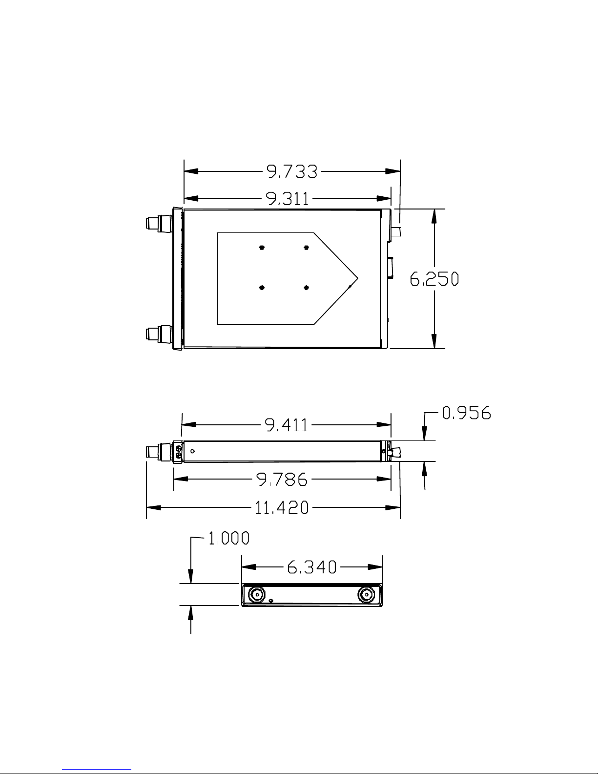
Height 1.0 inches (2.54 cm)
Width 6.25 inches (15.88 cm)
Depth 9.0 inches (22.86 cm)
Weight: 3.25 pounds (1.5 kg)
Mounting: Panel mounted, no shock mounting required
Temperature Range: -20 to +55 Celsius with short time operations at
+70 Celsius
Power Requirements:
Voltage 11.0 to 30.0 VDC
Current 0.5 Amp Rec. 3 Amp max transmit
Receiver:
VHF Frequency 118.00 to 136.975 MHz
Sensitivity 2 µV to provide a 6dB S+N:N
Channel Spacing 25 kHz
Stability
Selectivity
Audio output
AGC Characteristics From 10 µV to 200 µV the audio level will not
Transmitter:
Carrier Power 8W nom. RMS
Duty Cycle 50%
Manufacturer’s Model Number
Part Number VPN 0800105
±.002%
≥60dB
5W to 4Ω Spk 50mW to 600Ω Phone
vary more than 3db.
COM 2000
Revision 3 Page 6 of 31
March 2013
Page 7
I N S T A L L A T I O N A N D O P E R A T O R ’ S M A N U A L
C O M 2 0 0 0 – V H F T R A N S C E I V E R
V A L A V I O N I C S L T D
1.6 EQUIPMENT SUPPLIED
Table 2: Equipment Supplied
QTY DESCRIPTION PART NUMBER
1 COM 2000 – 760 Channel Radio
1 INSTALLATION KIT
0800105
651002
1.7 EQUIPMENT REQUIRED BUT NOT SUPPLIED
Table 3: Equipment Not Supplied
QTY DESCRIPTION PART NUMBER
1 Circuit Breaker 5 amp Potter & Brumsfield W58-2 (Ref
VPN 0331005)
1 Aircraft Cabin Speaker Ref aircraft parts manual for
specific part number
1 Contact Crimping Tool w/
Positioning Tool
AMP P/N 601966-1
AMP P/N 601699-5
1.8 LICENSE REQUIREMENTS
None
Revision 3 Page 7 of 31
March 2013
Page 8

I N S T A L L A T I O N A N D O P E R A T O R ’ S M A N U A L
C O M 2 0 0 0 – V H F T R A N S C E I V E R
V A L A V I O N I C S L T D
2 SECTION II - INSTALLATION
2.1 GENERAL INFORMATION
2.1.1 Scope
This section of the manual will provide the needed information to successfully complete the installation of your new
COM 2000 – VHF Transceiver. Please read this section completely before proceeding with the installation process.
Although the COM 2000 installation procedures are designed with the do-it-yourselfer in mind, we at Val Avionics
Ltd. strongly suggest that you seek the advice of a qualified avionics installation facility before beginning this or any
other installation project. Qualified avionics installation technicians can offer good advice as to time-tested
installation practices and techniques that can save you many hours of time and frustration.
2.2 UNPACKING AND INSPECTION
Use care when unpacking the equipment. Inspect the unit and supplied parts for visual signs of damage during
shipment. Examine the unit for loose screws, dents, broken buttons and other signs of damage that may have
occurred during shipment. Verify the contents of the container with the list in section 1.5. If any damaged or missing
parts are discovered during the inspection save the shipping material and contact the freight carrier to file a claim. If
it is suspected that parts were omitted from the container please feel free to contact Val Avionics Ltd., to acquire the
missing items.
2.3 EQUIPMENT INSTALLATION PROCEDURES
2.3.1 Cooling Requirements
Forced air-cooling is not required for the COM 2000 – VHF Transceiver. However, when planning the location for
mounting, ensure adequate spacing from heat producing sources such as heating or defrosting ducts.
2.3.2 Mounting Requirements
The COM 2000 mounting tray should be rigidly mounted in the avionics stack using the hardware provided in the
installation kit. Ensure that the mounting location will provide easy access and a clear view of the equipment’s front
panel from the pilot’s position. Ensure that the mounting position will provide adequate clearance between the unit
and the associated wire harness and the aircraft controls. Bracing at the rear of the unit should be installed to ensure
rigidity in the panel. Consult FAA Advisory Circular AC 43.13-2A for acceptable practices and techniques.
Revision 3 Page 8 of 31
March 2013
Page 9

I N S T A L L A T I O N A N D O P E R A T O R ’ S M A N U A L
C O M 2 0 0 0 – V H F T R A N S C E I V E R
V A L A V I O N I C S L T D
2.3.3 Wire Harness Fabrication
Val Avionics Ltd. Strongly recommends the use of a factory fabricated wire harness (VPN 751027) with your new
COM 2000 – VHF Transceiver. Use of the factory fabricated wire harness will ensure proper operation of the COM
2000, reduction in the occurrence of interfering signals and ground loops, greatly reduced installation time, and
provide prolonged trouble-free performance of your new equipment.
Although strongly recommended, it is not required to use the factory fabricated wire harness when installing the
COM 2000. A wiring harness can be fabricated in the field. Refer to appendix B of this manual for a complete
wiring diagram. The COM 2000 is connected to the aircrafts avionics bus via a 5 AMP circuit breaker. All wires
must be 22 AWG MIL-SPEC, unless otherwise noted in accordance with current regulations. Two and three
conductor shielded MIL-C-27500 or equivalent wire must be used where indicated. Use AMP Contact Crimping
Tool (AMP P/N 601966-1) with Positioning Tool (AMP P/N 601699-5) or equivalent to ensure good quality
contacts. Refer to FAA Advisory Circular AC 43.13-2A for acceptable practices and techniques.
2.3.4 COM 2000 Installation
2.3.4.1 Mounting
The COM 2000 is rigidly mounted in the aircrafts avionics stack. Once a location has been selected, a visual
inspection should be made of the area directly behind the panel which, will be occupied by the COM 2000 and
harness assembly for obvious obstructions such as heater ducts, control cables, fuel and oil lines or any other
obstruction. Pay particular attention to the control yoke assembly. It should be moved to the full limit of travel and
verified that sufficient clearance exists prior to beginning installation. Most aircraft instrument panels will already
have existing radio mounting cutouts. If the location you have selected requires that a mounting hole be cut, refer to
Figure 4: Panel Cut Out on Page 16 for the mounting template. Mark and cut the mounting holes as required.
Position the unit’s mounting tray in its upright position, and from the rear of the panel. With the unit held in place,
insert the two of the supplied 6-32 X 3/8” screws from the front and tighten as appropriate. The installing agency
must fabricate and attach rear support brackets to the aircraft structure behind instrument panel as appropriate to
support the rear of the COM 2000. Then, attach these brackets to the provided attachment points on the rear of the
unit with the supplied 6-32 1/4" Screws.
2.3.4.2 Antennas
One antenna is required for the COM 2000 installation. A standard COM antenna can be used with the unit such as a
COMANT CI-121 or equivalent. Follow the antenna manufacture’s installation Manual to ensure proper installation
of the antenna.
2.3.4.3 Audio
The COM 2000 has two auxiliary audio inputs and two audio outputs, Speaker audio and Headset audio. In
installations with two radio and/or more audio devices, it is strongly recommended that these audios be coupled to a
quality audio selector panel such as a Val Avionics AP 100. For complete details, refer to the interconnect wiring
diagrams in Appendix B.
2.4 POST INSTALLATION CHECK
Revision 3 Page 9 of 31
March 2013
Page 10

I N S T A L L A T I O N A N D O P E R A T O R ’ S M A N U A L
C O M 2 0 0 0 – V H F T R A N S C E I V E R
V A L A V I O N I C S L T D
2.4.1 Operational Check
Refer to section three of this manual. Check all functions of the COM 2000 for proper operation. Check the
operational functions of other equipment installed in the aircraft in accordance with the individual manufacture’s
operation manuals to insure that no cross interference exists as a result of this installation.
2.4.2 Final Inspection
Verify that the wiring is bundled away from all controls and that no part of the installation interferes with the
movement of the aircraft controls. Move all of the aircraft controls through their full range of movement while
visually verifying that the installation does not mechanically interfere with the control movement. Verify that the
wiring harnesses are properly secured to the aircraft structure in accordance with accepted practices as described in
AC 43.13 and that adequate strain relief and service loops have been provided. Ensure that there are no kinks or
sharp bends in the wire harnesses. Verify that the wire bundles are not exposed to any sharp or abrasive surfaces.
Complete log book entries, FAA form 337, weight and balance computations and other documentations as required.
2.5 LIMITATIONS
There are no known limitations to the operation of the COM 2000. Instructions for Continued Airworthiness and
Return to Service Instructions can be found in Appendix C.
Revision 3 Page 10 of 31
March 2013
Page 11
I N S T A L L A T I O N A N D O P E R A T O R ’ S M A N U A L
C O M 2 0 0 0 – V H F T R A N S C E I V E R
V A L A V I O N I C S L T D
3 SECTION III - OPERATION
3.1 GENERAL INFORMATION
3.1.1
This section will provide detailed operating instructions for your new COM 2000 – VHF Transceiver. Please read
this section completely to become familiar with all of the features of the unit.
3.1.2
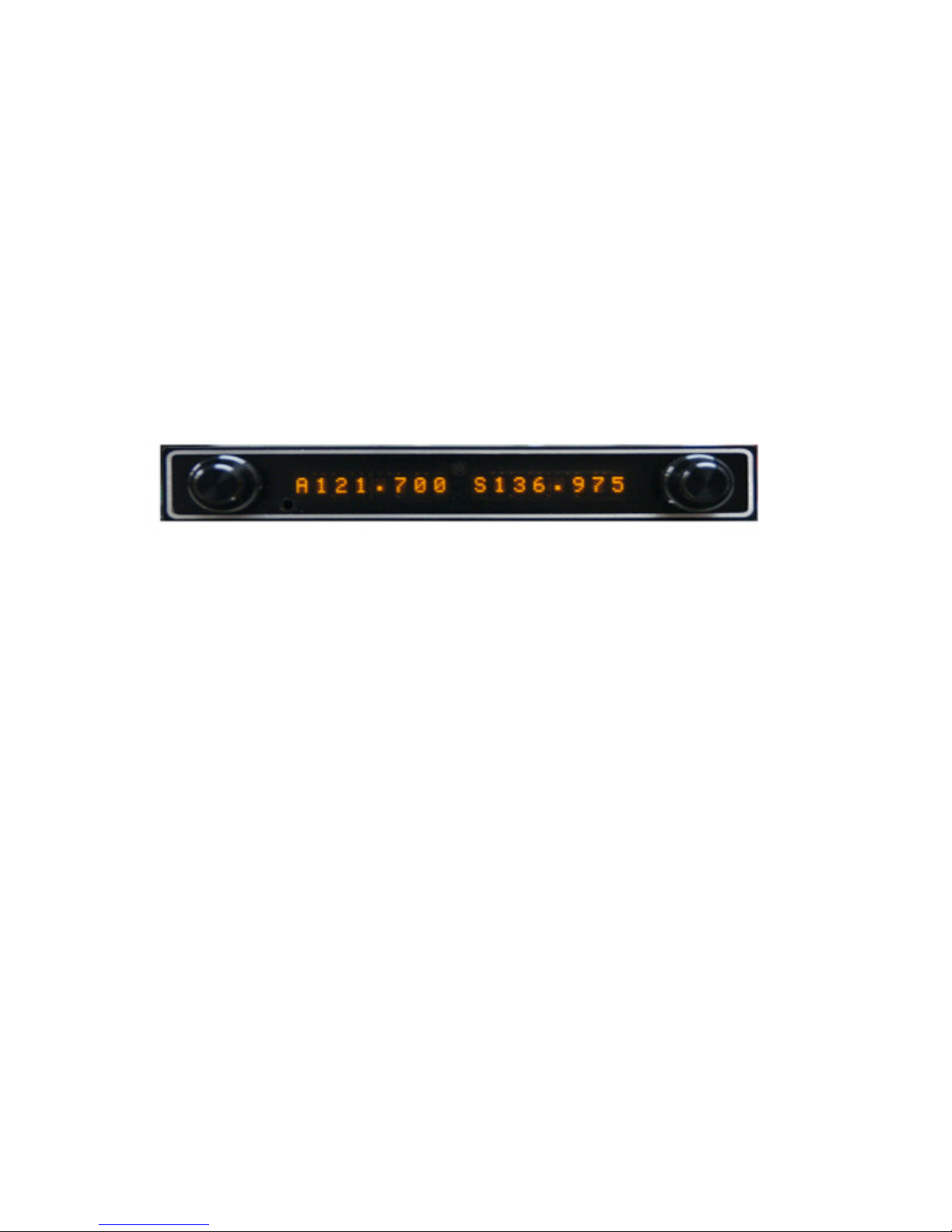
Upon power up the unit will display initialization codes. After initialization, the unit will display an active and
standby frequency represented by “Axxx.xxx Sxxx.xxx” with the x’s representing the frequency. The first
frequency starting with the “A” is the active frequency, and the “S” is the standby frequency. When the unit is
transmitting the “A” will be replaced with a “T” to represent active transmit. When the unit is selecting a memory
station, the “A” and “S” will no longer be visible and the active portion will contain the seven-character description
and the standby will contain the frequency associated with the description.
Scope
Figure 1: Unit Controls
Display Functions
3.1.3
Refer to Figure 1: Unit Controls. The user controls consist of two sets of concentric rotary knobs. Both sets of
knobs contain three parts, the inner knob (the small one) the outer knob (the large one) and a momentary push button
(the end of the small knob). The left outer inner knob controls the squelch as well as the position of the cursor in
memory edit. The left inner knob controls the volume, allows for selection of a stored memory, and selects
characters in memory edit. The right knobs control the frequency, whether it is the standby frequency or entering
the memory frequency.
Revision 3 Page 11 of 31
March 2013
User Controls
Page 12

I N S T A L L A T I O N A N D O P E R A T O R ’ S M A N U A L
C O M 2 0 0 0 – V H F T R A N S C E I V E R
V A L A V I O N I C S L T D
3.1.3.1 Turning the unit on/off
To turn the unit on, momentarily press the left hand inner knob. The unit will go through a short initialization
routine at start up and then begin operation at the same settings that were loaded at the last power down. To turn the
unit off, press and hold the left inner knob for three seconds.
3.1.3.2 Setting Active and Standby Frequency
The knob functions of the right hand set are as follow; the inner knob will change the frequency by KHz or the
numbers to the right of the decimal point (118.125) in 25kHz increments. The outer knob will change the frequency
by MHz or the numbers to the left of the decimal point (119.125) in 1 MHz increments. Only the frequency in the
standby position will change. The standby frequency is displayed at the bottom on the left side of the display and is
identified by the letter “S” to the left of the frequency (S108.15). To load the standby frequency in to the active
position, momentarily press on the inner knob. This will swap the standby frequency with the active frequency. The
active frequency is identified by the letter “A” at the left of the frequency display (A118.125).
3.1.3.3 Changing the Volume
Rotating the left hand inner knob controls the receiver’s audio volume. “VOL” will be displayed in the standby
frequency display and the volume level is indicated by the numeric value after “VOL” (i.e. “VOL 15”). The
volume level can be adjusted from 0 to 20 by rotating the left hand inner knob. Normal display operation resumes
after 2 seconds.
3.1.3.4 Changing the Minimum Received Signal Level (Squelch)
Rotating the left hand outer knob controls the receiver’s internal signal strength cutoff (Squelch). “SQL” will be
displayed in the standby frequency display and the volume level is indicated by the numeric value after “SQL” (i.e.
“SQL 15”). The squelch level can be adjusted from OFF to 20 by rotating the left hand inner knob. Normal
display operation resumes after 2 seconds.
3.1.3.5 Selecting a Stored Memory Station
A quick push of the left hand knob enters the stored station retrieval. If no memory stations are available, the
display will show “NO MEM” and return to normal operation. Rotating the inner left hand knob scrolls through the
previously entered memory stations. In the left side (previously the active display) the pre-programmed label will
be shown, and the right side (previously the standby display) will show the associated frequency. Once the desired
frequency is displayed, a quick push of the left hand knob will cause the selected frequency to be loaded into the
Standby window and the unit will return to normal operation. To exit without selecting a memory frequency, just
wait 5 seconds without twisting any knob and the display will return to normal, or push the right hand knob to exit
instantly.
3.1.3.6 Entering / Editing / Deleting a Stored Memory Station
Val Avionics does not recommend entering or editing stored frequencies in flight. Doing so can be a distraction to
the pilot.
Revision 3 Page 12 of 31
March 2013
Page 13

I N S T A L L A T I O N A N D O P E R A T O R ’ S M A N U A L
C O M 2 0 0 0 – V H F T R A N S C E I V E R
V A L A V I O N I C S L T D
3.1.3.6.1 Selecting a stored frequency to be created / edited /deleted
By pushing both left and right buttons, the unit will enter the stored frequency edit select mode. If there are no
frequencies entered, or the unit is selecting an open memory slot, the unit will show no text in the active window,
and the standby will display “<EMPTY>”. When adding a new frequency, rotate the inner left knob until the
display shows ““<EMPTY>”. To edit a currently existing frequency, rotate to the frequency / station label that is to
be edited.
3.1.3.6.2 Creating / Editing a stored frequency
Depress the left hand button to enter the edit mode, which is characterized by a blinking cursor at the leftmost
position of the label text. By rotating the left inner knob, a new character can be selected for the memory location.
By rotating the left outer knob, the position of the cursor can be changed. Once the label has been entered, rotating
the right knobs will allow for the frequency to be selected. When the data is entered as desired, pressing the left
hand button will exit the edit mode and return to the previous state. If desired, additional frequencies can be edited
or added by repeating the above steps.
3.1.3.6.3 Deleting a Stored frequency
Once the undesired frequency has been selected (see 3.1.3.6.1), press the right hand knob. A confirmation will
appear in the Standby window, rotate the left hand inner knob to select “Y”, and press the right hand knob to
confirm. This deletes the stored information.
3.1.3.6.4 Exiting the stored frequency editing functions
To exit and return to normal operation, pressing both buttons will return to normal operation.
3.2 System Configuration
3.2.1
During startup, the unit’s setup can be assessed by pressing both buttons simultaneously until the unit shows an
active frequency and “MicG xx”. In this mode, the Microphone Gain and Sidetone values can be configured. In
this mode, the unit will transmit and receive any frequency that is located in the active window and the frequency
knobs (right hand inner and outer) will directly control the active frequency. The left hand inner knob adjusts the
Microphone gain, and the left hand outer knob adjusts the Sidetone. To exit this mode and resume normal
operation, press both buttons simultaneously.
Accessing Setup Functions
Revision 3 Page 13 of 31
March 2013
Page 14

I N S T A L L A T I O N A N D O P E R A T O R ’ S M A N U A L
C O M 2 0 0 0 – V H F T R A N S C E I V E R
V A L A V I O N I C S L T D
4 SECTION IV - WARRANTY AND SERVICE
4.1 LIMITED WARRANTY
The equipment delivered with this Standard Factory Warranty is manufactured by Val Avionics, Ltd. and is
guaranteed against defective materials and workmanship for one year from date of original retail purchase. Any unit
found to be defective due to material and workmanship during the warranty period will be repaired or replaced at the
sole discretion of Val Avionics Ltd.
Val Avionics, LTD liability under this warranty is limited to servicing, repairing or adjusting any equipment
returned prepaid to the Val Avionics’ factory by express written or verbal authorization for that purpose and to
repair or replace defective parts thereof.
If, upon examination, it is determined that a malfunction has been caused by misuse of the equipment, installation or
operation not in accordance with factory instructions, accident or negligent damage, alterations of any manner, and
repair by other than the factory, the repairs will not be covered under the warranty. In such cases, an estimate will be
submitted for approval before repair is initiated. In most cases, Val avionics, Ltd. will provide 72-hour turn around
on its warranty and repair service. We recommend that contact be made with the FACTORY CUSTOMER
SERVICE DEPARTMENT prior to any unit return and obtain RETURN AUTHORIZATION AND
INSTRUCTIONS. This will provide proper control and expedite service.
Val Avionics, Ltd. reserves the right of continuous product development without obligation to install changes in
previously manufactured products.
Installation of Val Avionics, Ltd. products must conform to methods acceptable by the Federal Aviation
Administration as described in the appropriate Federal Aviation Regulations (FAR’s) and Advisory Circulars
(AC’s).
To ensure proper warranty registration, type or print clearly the application information on the enclosed
PRODUCTS WARRANTY REGISTRATION FORM and return to Val Avionics, Ltd.
4.2 SERVICE
Repair service for the COM 2000 – VHF Transceiver is available at our manufacturing facility. Units in need of
servicing should be returned prepaid to Val Avionics Ltd at the following addresses.
If you are shipping by the US Postal Service address To:
Val Avionics
P.O. Box 13025
Salem, OR 97309
If you are shipping by FedEx, UPS or other shipping company, address to:
Val Avionics
2950 Pringle Road SE
Salem, OR 97302
Revision 3 Page 14 of 31
March 2013
Page 15
I N S T A L L A T I O N A N D O P E R A T O R ’ S M A N U A L
C O M 2 0 0 0 – V H F T R A N S C E I V E R
V A L A V I O N I C S L T D
5 Appendix A – INSTALLATION DRAWINGS AND
CONNECTOR LAYOUT
Revision 3 Page 15 of 31
March 2013
Page 16
I N S T A L L A T I O N A N D O P E R A T O R ’ S M A N U A L
C O M 2 0 0 0 – V H F T R A N S C E I V E R
Figure 2: Physical Dimensions
V A L A V I O N I C S L T D
Figure 3: P1 Connector Pin Out
Figure 4: Panel Cut Out
(Drawing Not to Scale)
Figure 5: Mounting Tray Assembly Exploded View
Revision 3 Page 16 of 31
March 2013
Page 17
C O M 2 0 0 0 – V H F T R A N S C E I V E R
Pin
Function
I/O
Pin
Function
I/O
V A L A V I O N I C S L T D
I N S T A L L A T I O N A N D O P E R A T O R ’ S M A N U A L
Table 4: Rear Connector Pin Functions (Serial number 20720 to current)
1 RS-232 Out Output
2 Aux In 2 Input
3 Speaker Ground
4 Headphone Ground
5 Mic Ground
6 Key Input
7 Main Ground
8 Main Power
9 RS-232 In Input
10 Aux In 1 Input
11 Speaker Output
12 Headphone Output
13 Mic Audio Input
14 Active/Standby Toggle Input
15 NC
Table 5: Rear Connector Pin Functions (Serial number 20500 to 20719)
1 RS-232 Out Output
2 Aux In 2 Input
3 Speaker Ground
4 Headphone Ground
5 Mic Ground
6 Key Input
7 Main Ground
8 Main Power
9 RS-232 In Input
10 Aux In 1 Input
11 Speaker Output
12 Headphone Output
13 Mic Audio Input
14 Main Ground
15 Main Power
Revision 3 Page 17 of 31
March 2013
Page 18
I N S T A L L A T I O N A N D O P E R A T O R ’ S M A N U A L
C O M 2 0 0 0 – V H F T R A N S C E I V E R
V A L A V I O N I C S L T D
6 Appendix B – WIRING DIAGRAMS
Figure 6: COM 2000 Basic Wiring Diagram
Figure 7: Interface with AP100
Revision 3 Page 18 of 31
March 2013
Page 19

I N S T A L L A T I O N A N D O P E R A T O R ’ S M A N U A L
C O M 2 0 0 0 – V H F T R A N S C E I V E R
V A L A V I O N I C S L T D
7 Appendix C – Certifications
7.1 TSO Certification:
This device has been tested and found to meet specification of TSO-C169a.
Revision 3 Page 19 of 31
March 2013
Page 20

I N S 4 2 9 I N T E G R A T E D N A V I G A T I O N S Y S T E M
I N S T A L L A T I O N A N D O P E R A T O R ’ S M A N U A L
V A L A V I O N I C S L T D
8 Appendix D – INSTRUCTIONS FOR CONTINUED
AIRWORTHINESS
8.1 MAINTENANCE INSTRUCTIONS
Maintenance of the COM 2000 – VHF Transceiver is on condition only. No periodic maintenance is required. If
unit is found to be out of calibration, send unit in for service. If unit is removed for service, upon re-installation
perform Post Installation check as described in section 2.4 of this manual.
Revision 3 Page 20 of 31
May 2013
Page 21

I N S T A L L A T I O N A N D O P E R A T O R ’ S M A N U A L
C O M 2 0 0 0 – V H F T R A N S C E I V E R
V A L A V I O N I C S L T D
9 Appendix E – RS-232 Command Interface
This appendix includes the interface specifications for the RS-232 serial port. The RS-232 port can be used
to input active and standby frequencies as well as using an external serial resolver such as an EFIS system.
The interface format conforms to NMEA 0183 message format specifications. For improved compatibility,
the COM 2000 / COM 2KR accepts all commands for the INS 429 / NAV 2000 / NAV 2KR
9.1 Input Commands
The following input command messages are supported:
• Request data output
• Set active COM frequency data from a remote source
• Set standby COM frequency data from a remote source
• Set COM Volume and Squelch Level
• Set COM Mic Gain and Sidetone
9.2 Output Messages
The COM 2000 / COM 2KR output messages include:
• Reset status
• Communications Error
• COM Receiver status
• COM audio mode
• COM microcontroller software version
• COM Volume and Squelch Level
• COM Mic Gain and Sidetone
9.3 Data Format
The data format for serial communication is:
• Baud rate 9600
• Data bits 8
• Stop bits 1
• Parity none
9.4 Default Message Output
At system start when the COM 2000 / COM 2KR is configured to operate in normal mode, the following
messages will be configured for output and the specified rates:
• COM Receiver status at 1 Hz (low rate)
These default rates can be changed by using the Request Data Output message.
Revision 3 Page 21 of 31
March 2013
Page 22

I N S 4 2 9 I N T E G R A T E D N A V I G A T I O N S Y S T E M
I N S T A L L A T I O N A N D O P E R A T O R ’ S M A N U A L
9.5 Message Formats
All messages will conform to the NMEA 0183 proprietary message format as follows. All characters will
be standard ASCII characters. No binary data characters will be used.
“$”.....................................Start of message character, ASCII “$” (024h)
“P”.....................................Proprietary message identifier
“MRR” ..............................II Morrow company identifier
c.........................................Message class identifier. Used to identify a message as either a
nn ......................................Message identifier, two-digit number in ASCII characters.
d…d ..................................Message data characters defined for each message.
chksum ..............................Message checksum, including message identifier through data
<CR>.................................ASCII carriage return (0Dh)
<LF> .................................ASCII line feed (0Ah)
The maximum message length, including the start of message character (“$”) and the end of message
<CR><LF> sequence, is 25 bytes.
This message format is the same as is used in the INS 429 / NAV 2000 / NAV 2KR. The COM 2000 /
COM 2KR will be able to accept all messages intended for a INS 429 / NAV 2000 / NAV 2KR without
generating a serial communications error. It will ignore all of those messages. Those messages have been
included for completeness.
V A L A V I O N I C S L T D
COMM of VHF NAV message. Those message types, which are also
supported by the VAL COM 2000 VHF Transceiver, will use the “C”
identifier to allow the INS 429 to accept COMM radio commands from
existing products. All other messages will use the “V” identifier to
indicate that they relate to a VHF NAV receiver.
characters. The two-digit checksum is generated by adding all values
of valid characters together, ignoring carry (if any). This value is
converted into two encoded hex1 characters (30h-3Fh).
1
Encoded Hex: each character consists of 4 bits of data placed in the low order nibble +30h. For example, the 8-bit
value of 5Fh would be encoded as two characters with values of 35h and 3Fh, which map to the ASCII characters
“5” and “?” respectively.
Revision 3 Page 22 of 31
May 2013
Page 23

I N S 4 2 9 I N T E G R A T E D N A V I G A T I O N S Y S T E M
I N S T A L L A T I O N A N D O P E R A T O R ’ S M A N U A L
V A L A V I O N I C S L T D
9.6 Message Definitions
Input Messages
REQUEST DATA OUTPUT
This input is used to request an output message to be sent by the INS 429 / COM 2000.
Message format:
“V” ...............................Message class. This is a VHF NAV message.
“24” ..............................Message identifier.
ii ....................................Output identifier of requested message, two ASCII characters.
dd...................................Message data, two encoded hex2 characters (30h-3Fh), used for specific output
request. Set to “00” if not needed. These characters are used for such items as
selecting a specific EEPROM address to output.
A....................................Request type: (ASCII) “0”= output repeatedly at low speed (1 Hz); “H” = output
repeatedly at high speed (10 Hz).
ii Output Dd Data Description a
“20” Reset Status “00”
“21” CDI, GSI, and Flags “00”
“22” Decoded OBS Setting “00”
“23” Radial from Active VOR “00”
“28” Receiver Status “00”
“30” NAV Microntroller Software Version “00”
“32” ADC Data Output cc ADC channel: “00”
“35” Comm Transceiver Status “00”
“36” Comm Software Version “00”
“71” Comm Volume and Squelch “00”
“72” Comm Mic Gain and Sidetone “00”
Table 6 - Data Output Requests
Example messages:
$PMRRV242100L<chksm><CR><LF>
Request periodic output of CDI, GSI, and related flags at low (1Hz) rate.
$PMRRV2432050<chksm><CR><LF>
Request a single output of ADC data from channel 5.
to “08”
“0”
“0”, “L”, “H”
“0”, “L”, “H”
“0”, “L”
“0”
“0”
“0”
“0”
“0”
“0”, “L”
“0”
2
Encoded Hex: each character consists of 4 bits of data placed in the low order nibble +30h. For example, the 8-bit
value of 5Fh would be encoded as two characters with values of 35h and 3Fh, which map to the ASCII characters
“5” and “?” respectively.
Revision 3 Page 23 of 31
May 2013
Page 24

I N S 4 2 9 I N T E G R A T E D N A V I G A T I O N S Y S T E M
I N S T A L L A T I O N A N D O P E R A T O R ’ S M A N U A L
SET ACTIVE VOR/LOC FREQUENCY AND RECEIVER FUNCTION
This message is used to set the standby VOR or Localizer frequency as well as the receiver operating
function. The INS 429 can detect if the supplied frequency corresponds to a VOR or a Localizer channel,
so this command will work for both types of NAV aids.
V A L A V I O N I C S L T D
Message format:
$PMRV27E4N<chksm><CR><CR><LF>
This example command would set the active VOR frequency to 117.100 MHz. This can be interpreted by
noting that the ASCII ‘E’ corresponds with 45h, + 30h = 75h, converted to decimal equals 117 for the MHz
portion of the command. The kHz portion converts ASCII ‘4’ to 34h, - 30h = 4h, x 25 kHz steps = 100
kHz. This command would also set the receiver function to normal, leaving the standby channel inactive.
Note: The INS 429 will check input frequencies for validity. An RS-232 serial error message output will be
generated if the frequency is invalid.
SET STANDBY VOR/LOC FREQUENCY AND RECEIVER FUNCTION
This message is used to set the standby VOR or Localizer frequency as well as the receiver operating
function. The INS 429 can detect if the supplied frequency corresponds to a VOR or a Localizer channel,
so this command will work for both types of NAV aids.
Message format:
“V”………..Message class. This is a VHF NAV message.
“28”………Message identifier.
mk………..Standby VOR/LOC frequency:
m = desired frequency in MHz in hexadecimal, where m = desired frequency – 30h,
with desired frequency in range of 108 to 117 MHz.
k = desired frequency in kHz, where k = (desired frequency / 25 kHz) + 30h,
desired frequency in range of 000 to 975 kHz in 50 kHz steps, or the even numbers
from 30h to 56h.
a………….Receiver function: N = normal, 0 = unchanged.
Example message:
$PMRRV28?PN<chksm><CR><LF>
This example command would set the standby VOR frequency to 111.800 MHz. This is interpreted by
noting that the ASCII ‘?’ corresponds with 3Fh, + 30h = 7Bh, converted to decimal equals 111 for the
MHz portion. The kHz portion converts ASCII ‘P’ to 50h, -30h, -30h yields 20h, x 25 kHz steps = 800 kHz
portion. This command would also set the receiver function to normal, so the receiver would receive only
the active VOR channel.
Note: The INS 429 will check input frequencies for validity. An RS-232 serial message output will be
generated if the frequency is invalid.
Revision 3 Page 24 of 31
May 2013
Page 25

I N S 4 2 9 I N T E G R A T E D N A V I G A T I O N S Y S T E M
I N S T A L L A T I O N A N D O P E R A T O R ’ S M A N U A L
V A L A V I O N I C S L T D
SET STANDBY COMM FREQUENCY AND TRANSRECEIVER FUNCTION
This message is issued to set the standby COM frequency.
Message format:
“V” ..................... Message class. This is a VHF NAV message.
“29”.................... Message identifier.
Mk...................... Standby COM frequency:
m = desired frequency in MHz in hexadecimal, where m = desired frequency - 30h, with desired frequency
in range of 118 to 136 MHz, or 162 MHz.
k = desired frequency in kHz, where k = (desired frequency / 25 kHz) + 30h, with desired frequency in
range of 000 to 975 kHz in 25 kHz steps.
a……………..Transceiver function: N = normal, 0 = unchanged.
Example message:
$PMRRV29G4M<chksm><CR><LF>
This example command would set the standby VOR frequency to 119.100 MHz. This is interpreted by
noting that the ASCII ‘G’ corresponds with 47h, + 30h = 77h, converted to decimal equals 119 for the MHz
portions. The kHz portion converts ASCII ‘4’ to 34h, - 30h yields 4h x 25 kHz steps = 100 kHz.
Note: The COM 2000 will check input frequencies for validity. An RS-232 serial error message output will
be generated if the frequency is invalid.
SET ACTIVE COMM FREQUENCY AND TRANSCEIVER FUNCTION
This message is used to set the Active COMM frequency as well as he COMM transceiver function.
This message is only available in normal mode.
Message format:
“V” ..................Message class. This is a VHF NAV message.
“42”.................Message identifier.
mk ...................Active COMM frequency:
m = desired frequency in MHz in hexadecimal, where m = desired frequency –
30h, with desired frequency in range of 118 to 136MHz, or 162MHz.
k = desired frequency in kHz, where k = (desired frequency / 25kHz steps.)
a = Transceiver function: N = normal, 0 = unchanged.
Example message:
$PMRRV42G4N<chksm><CR><LF>
This example command would set the active VOR frequency to 119.100MHz and place the COMM radio
in Normal receive mode. This is interpreted by noting that the ASCII ‘G’ corresponds with 47h, + 30h =
77h, converted to decimal equals 119 for the MHz portion. The KHz portion converts ASCII ‘4’ to 34h, 30h yields 4h, x 25KHz steps = 100 kHz.
Note: The COM 2000 will check input frequencies for validity. An RS-232 serial error message output will
be generated if the frequency is invalid.
Revision 3 Page 25 of 31
May 2013
Page 26

I N S 4 2 9 I N T E G R A T E D N A V I G A T I O N S Y S T E M
I N S T A L L A T I O N A N D O P E R A T O R ’ S M A N U A L
V A L A V I O N I C S L T D
SET OMNI-BEARING SELECT (OBS) VALUE
This message is used to set the OBS value used by the INS 429 as the elected radial for computing the
course deviation from a VOR. This message will have no effect unless the INS 429 is configured to use the
internal OBS source, or a serial OBS source.
Message format:
“V” .................. Message class. This is a VHF NAV message.
“34”................. Message identifier.
vvv .................. OBS Value in degrees, ranging from “000” to “359”.
Example message:
$PMRRV34310<chksm><CR><LF>
Set the OBS value to 310 degrees.
V
OLUME AND SQUELCH CONTROL
This message is used to adjust the volume and squelch levels of the COM unit
Message format:
"V" ..................... Message class - VHF NAV Message
"71" .................... Message Identifier
"vs"..................... Volume level and Squelch Level:
v = Desired volume level in encoded hexadecimal, where v = desired
level + 0x30 with a range between 0 - 20, 0 being muted
s = Desired squelch level in encoded hexadecimal, where s = desired level
+ 0x30 with a range between 0 - 20, 0 being off
Example Message:
$PMRRV71;?<chksum><CR><LF>
This example command would set the volume level at 11 and the squelch at 15.
M
IC GAIN AND SIDETONE CONTROL
This message is used to adjust the volume and squelch levels of the COM unit
Message format:
"V" ..................... Message class - VHF NAV Message
"72" .................... Message Identifier
"ms".................... Volume level and Squelch Level:
m = Desired mic gain level in encoded hexadecimal, where m = desired
level + 0x30 with a range between 1 - 20
s = Desired sidetone level in encoded hexadecimal, where s = desired level
+ 0x30 with a range between 1 - 20.
Revision 3 Page 26 of 31
May 2013
Page 27

I N S 4 2 9 I N T E G R A T E D N A V I G A T I O N S Y S T E M
I N S T A L L A T I O N A N D O P E R A T O R ’ S M A N U A L
Example Message:
$PMRRV72;?<chksum><CR><LF>
This example command would set the mic gain level at 11 and the sidetone at 15.
OUTPUT MESSAGES
RESET STATUS
This message is sent to indicate to the host that the INS 429 / COM 2000 is running and ready to accept
data on the serial port. It will be sent once upon startup and when requested by the host.
Message format:
“V”………..Message class. This is a VHF NAV message.\
“20”………Message identifier.
Example message:
$PMRRV20<chksm><CR><LF>
INS 429 is running and ready to accept serial input.
CDI, GSI, AND RELATED FLAGS
This message outputs the current values of the CDI, GSI, and their related flags. After power up this
message will be output at a 10 Hz rate.
Message format:
“V” ..................... Message class. This is a VHF NAV message.
“21”.................... Message identifier.
cc........................ CDI deflection. An eight-bit value indicating the amount of deflection of the
gg ....................... GSI deflection. An eight-bit value indicating the amount of deflection of the GSI
ff......................... Flags. Eight bits for HNAV and VNAV related flags, represented as two
V A L A V I O N I C S L T D
CDI needle, represented as two encoded hex3 digits. The CDI deflection is a
twos complements signed integer in the range of –100 to 100. –100 indicates full
left deflection, 0 indicates no deflection, and 100 indicates full right deflection.
needle, represented as two encoded hexXX digits. The CDI deflection is a twos
complement signed integer in the range of –100 to 100. –100 indicates full
deflection upwards, 0 indicates no reflection, and 100 indicates full deflection
downwards.
encoded hex digits.
Bit 1 (1sb) Back Course enable (1 = enabled)
Bit 2 Localizer detect (1 = using localizer)
3
Encoded Hex: each character consists of 4 bits of data placed in the low order nibble +30h. For example, the 8-bit
value of 5Fh would be encoded as two characters with values of 35h and 3Fh, which map to the ASCII characters
“5” and “?” respectively.
Revision 3 Page 27 of 31
May 2013
Page 28

I N S 4 2 9 I N T E G R A T E D N A V I G A T I O N S Y S T E M
I N S T A L L A T I O N A N D O P E R A T O R ’ S M A N U A L
Example message:
$PMRRV21817??:<chksm><CR><LF>
This message indicates a full left CDI deflection (-127), a full up GSI deflection (127), both the GSI and
NAV flags/superflags are valid, TO flag set, FROM flag not set, using a localizer, with no back course
enable.
DECODED OBS SETTING
This message outputs the current OBS setting, which may be read from an external resolver or from user
input to the front panel. After power up this message will be sent at a 10 Hz rate.
Message format:
“V” ..................... Message class. This is a VHF NAV message.
“22”.................... Message identifier.
v ......................... Valid flag. “0” = OBS invalid/not present, “V” = OBS setting is valid.
ddd ..................... Three digit OBS setting, in degrees. Values are in the range of “000” to “359”.
Example message:
$PMRRV22V170<chksm><CR><LF>
A valid OBS setting of 170 degrees.
RADIAL FROM ACTIVE VOR
This message outputs the current bearing from the active VOR station. This message will be output even
when a localizer is being tracked by the NAV receiver. In this case, the bearing will be marked as invalid.
After power up this message will be sent at a 10 Hz rate.
Message format:
“V” ..................... Message class. This is a VHF NAV message.
“23”.................... Message identifier.
v ......................... Valid flag. “0” = bearing not valid, “V” = bearing is valid.
dddf .................... Bearing to a resolution of 1/10th of a degree. ddd = three digit bearing in
Example message:
$PMRRV23V1654<chksm><CR><LF>
A valid bearing of 165.4 degrees FROM the active VOR station.
V A L A V I O N I C S L T D
Bit 3 FROM flag (1 = From)4
Bit 4 TO flag (1 = To)
Bit 5 GSI superflag (1 = valid)
Bit 6 GSI valid (1 = valid)\
Bit 7 NAV superflag (1 = valid)
Bit 8 (msb) NAV valid (1 = valid)
degrees, ranging from “000” to “359”. f = 1/10th of a degree.
4
The TO and From flag can not both be 1, indicating that they are both valid. They can both be zero, indicating that
neither is valid. This situation will occur whenever the receiver determines that it is within the “cone of confusion”
directly over the VOR, or when no signal is being received.
Revision 3 Page 28 of 31
May 2013
Page 29

I N S 4 2 9 I N T E G R A T E D N A V I G A T I O N S Y S T E M
I N S T A L L A T I O N A N D O P E R A T O R ’ S M A N U A L
V A L A V I O N I C S L T D
COMMUNICATIONS ERROR
This message is used to indicate a communication error.
Message format:
“V” ..................... Message class. This is a VHF NAV message.
“27”.................... Message identifier.
e.......................... Error code: (ASCII)
“0” = input message checksum error.
“1” = unknown message.
“2” = error or mismatch in message data.
Example message:
$PMRRV271<chksm><CR><LF>
Received an unknown message.
NAV RECEIVER STATUS
This message is used to output the current status of the NAV receiver. It will be output upon request or
whenever the status changes.
Message format:
“V” ..................... Message class. This is a VHF NAV message
“28”.................... Message identifier
mk ...................... Standby NAV frequency: m = MHz, where m + 30h = desired MHz frequency
in the range of 108 to 117 MHz. k= (desired frequency / 25 kHz) + 30h, with
desired frequency in range of 000 to 975 kHz in 50 kHz steps.
s.......................... Status: “N” = Normal mode, “M” = Monitor mode
Example message:
$PMRRV28E4?PM<chksm><CR><LF>
Active NAV frequency is 117.100 MHz, Standby NAV frequency is 111.800 MHz, receiver is in monitor
mode.
NAV M
ICROCONTROLLER SOFTWARE VERSION
This message is used to output the version string for the NAV microcontroller software.
Message format:
“V” ..................... Message class. This is a VHF NAV message.
“30”.................... Message identifier.
vvvv ................... Software version in ASCII
e.......................... Engineering version flag:
“R” = Released version.
“E” = Engineering version.
Example message:
$PMRRV300103E<chksm><CR><LF>
NAV Microcontroller software is version 1.03. It is an engineering version.
Revision 3 Page 29 of 31
May 2013
Page 30

V A L A V I O N I C S L T D
C
OM TRANSCEIVER STATUS
I N S 4 2 9 I N T E G R A T E D N A V I G A T I O N S Y S T E M
I N S T A L L A T I O N A N D O P E R A T O R ’ S M A N U A L
This message outputs the result of a specific system test.
Message format:
“V” ..................... Message class. This is a VHF NAV message.
“35”.................... Message identifier.
mk ...................... Active frequency: m = MHz, where m = desired MHz frequency – 30h, ranging
from 118 to 136 MHz, 162 (i.e., 76h to 88h, A2h); k = (kHz offset / 25 kHz) +
30h, ranging from 000 to 975 kHz steps.
mk ...................... Standby frequency: m = MHz, where m = desired MHz frequency – 30h,
ranging from 118 to 136 MHz, 162 (i.e., 76h to 88h, A2h); k = (kHz offset / 25
kHz) + 30h, ranging from 000 to 975 kHz steps.
a.......................... Transceiver status:
R = Normal receive
T = Transmit enabled
S = Stuck mic
F = Comm failure
s.......................... Squelch test setting: (ASCII) 0 = automatic; 1 = test
Example message:
$PMRRV35G4LFR0<chksm><LF>
Active frequency is 119.100 MHz, the standby frequency is 124.550 MHz, receiver function, squelch is
automatic.
C
OM SOFTWARE VERSION
This message is used to output the version string for the VHF COM receiver software.
Message format:
“V” ..................... Message class. This is a VHF NAV message.
“36”.................... Message identifier.
vvvv ................... Software version in ASCII
Example message:
$PMRRV300103<chksm><CR><LF>
COM software is version 1.03.
V
OLUME AND SQUELCH SETTING
This command is sent anytime there is a change in either the volume or squelch settings, or is requested by
using a Request Data Output "24" command.
Message format:
"V" ................. Message class - VHF NAV Message
"71" ................ Message Identifier
"vs"................. Volume level and Squelch Level:
v = Desired volume level in encoded hexadecimal, where v = desired
level + 0x30 with a range between 0 - 20, 0 being muted
s = Desired squelch level in encoded hexadecimal, where s = desired level
+ 0x30 with a range between 0 - 20, 0 being off
Revision 3 Page 30 of 31
May 2013
Page 31

Example Message:
$PMRRV71;?<chksum><CR><LF>
This example command shows the volume level at 11 and the squelch at 15.
M
IC GAIN AND SIDETONE
This command is sent anytime there is a change in either the volume or squelch settings, or is requested by
using a Request Data Output "24" command.
Message format:
Example Message:
$PMRRV72;?<chksum><CR><LF>
This example command shows the mic gain level at 11 and the sidetone at 15.
I N S 4 2 9 I N T E G R A T E D N A V I G A T I O N S Y S T E M
V A L A V I O N I C S L T D
I N S T A L L A T I O N A N D O P E R A T O R ’ S M A N U A L
"V".............. Message class - VHF NAV Message
"72"............. Message Identifier
"ms" ............ Volume level and Squelch Level:
m = mic gain level in encoded hexadecimal, where m = desired level + 0x30
with a range between 1 - 20
s = sidetone level in encoded hexadecimal, where s = desired level + 0x30
with a range between 1 - 20.
Revision 3 Page 31 of 31
May 2013
 Loading...