

Page 1
Upgrading and Maintaining Your VAIO Digital Studio™ Computer
Upgrading and
Maintaining Your VAIO
Digital Studio™
Computer
In the future you may want to increase the functionality of your computer. This
section describes how to open your computer and insert an add-on board, add
memory, replace the lithium battery, and install an additional hard disk drive. For
more information on upgrading your Sony computer, see the computer System
Reference Manual. You can download the System Reference Manual from the
Sony Web site at http://www.sony .com/pcsupport.
Overview
The procedures in this section assume that you are familiar with the general
terminology associated with personal computers and with the regulatory
compliance required for using and modifying electronic equipment. Observe
proper safety precautions when you modify your computer . Read “Notes on Use”
in the VAIO Digital Studio™ Computer User Guide before upgrading your Sony
computer.
Always switch the power off before you open the system or connect your
computer to peripheral equipment. Otherwise, damage may occur to the
integrated circuits in your computer.
Electrostatic discharge (ESD) can damage disk drives, add-on cards, and
other components. Follow the procedures described here only at an ESD
workstation. If such a station is not available, do not work in a carpeted area
and do not handle materials that produce or hold static electricity (for
example, cellophane wrappers). Ground yourself by maintaining continuous
contact with an unpainted metal portion of the chassis while performing the
procedure.
1
Page 2
Removing the Side Cover
If you remove the side cover immediately after you shut down your computer,
the components may be too hot to touch. Wait until the internal parts of the
system unit cool down before you attempt to remove the side cover.
To remove the side cover
1 Shut down your computer and turn off all peripheral devices, such as your
printer.
2 Unplug your computer and any peripheral devices.
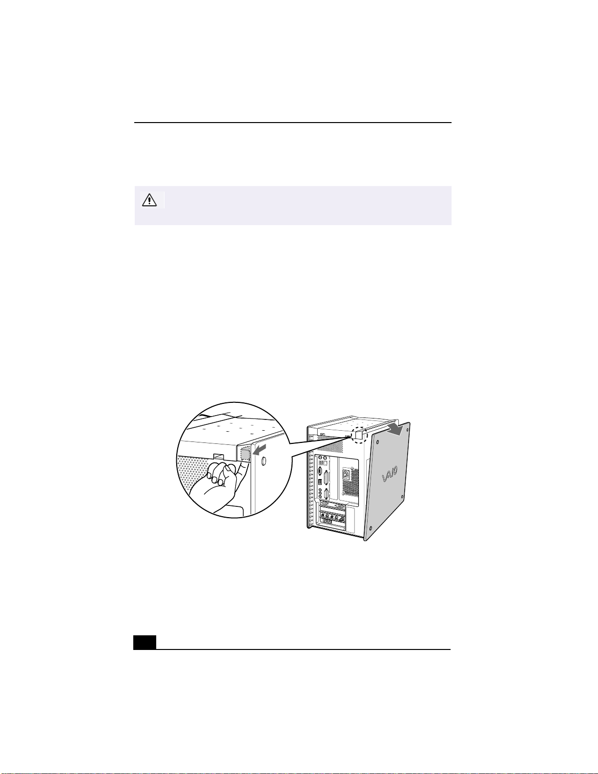
3 Locate the tab on the upper right side of the rear panel, and pull it back until
the side cover releases.
4 Lift the side cover away from the unit and set aside.
Removing the Side Cover
2
Page 3
Inserting a PCI Add-on Board
Inserting a PCI Add-on Board
Your computer has one open PCI expansion slot, depending on the configuration.
This slot enables you to install an add-on board to expand the functionality of
your system. The length of the add-on board should not exceed 9.05 inches.
✍
Add-on board configuration varies by model. Some models, such as Configure-toOrder (CTO) systems, may contain preinstalled add-on cards.
Make sure you observe the proper safety precautions when you add boards to
your Sony computer. See “Notes on Use” in the
Computer User Guide
.
To insert an add-on board
1 Shut down your computer and turn off all peripheral devices, such as your
printer.
2 Unplug your computer and any peripheral devices.
3 Remove the side cover as described in “Removing the Side Cover.’’
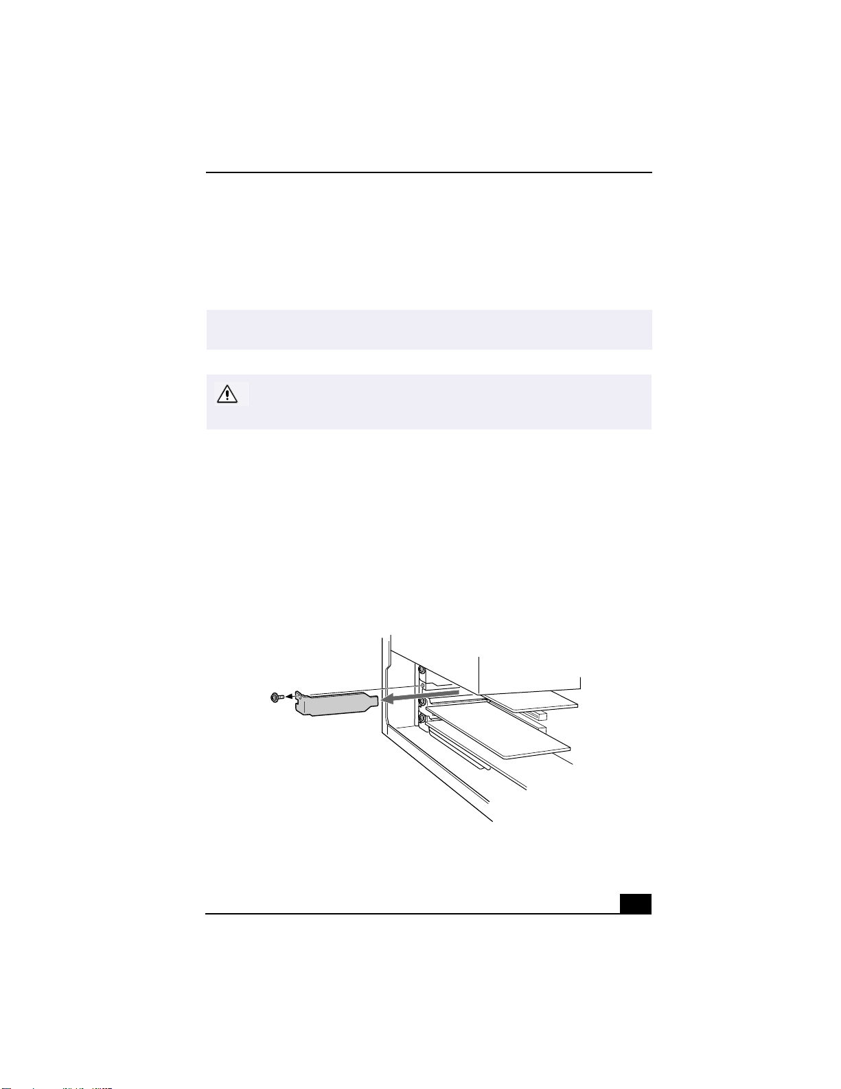
4 Locate the available expansion slot. Remove the screw, and then remove the
slot cover.
VAIO Digital Studio™
Removing the Slot Cover
3
Page 4
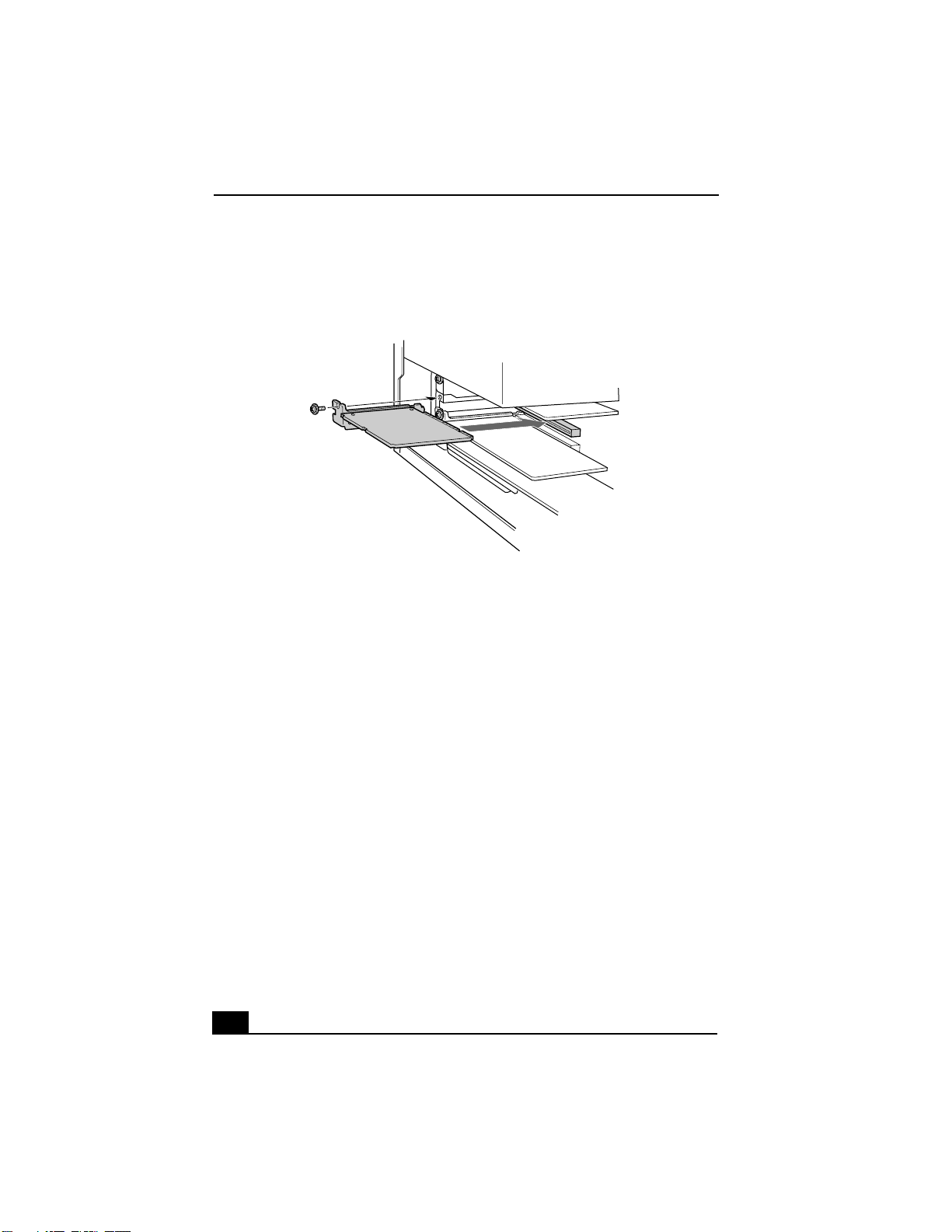
5 Install the add-on board by inserting it into the expansion slot and secure it
with the screw from the expansion slot.
Installing an add-on board
6 Attach any internal cables that the board requires (see the manual that came
with the add-on board).
7 Replace the side cover as described in “Replacing the Side Co ver.’’
8 Reconnect all peripheral devices and the power cord, and then turn on the
computer.
4
Page 5
Adding Memory
Adding Memory
The computer has four available memory slots. For memory upgrades, use only
PC-800 Direct Rambus RIMM modules in pairs. You can purchase additional
memory modules, accessories, and peripheral equipment from your local retailer.
Make sure you observe the proper safety precautions when you add RIMMs
to your Sony computer. See “Notes on Use” in the
Computer User Guide
.
To install memory
1 Shut down your computer and turn off all peripheral devices, such as your
printer. Wait for your computer to cool down.
2 Unplug your computer and any peripheral devices.
3 Remove the side cover as described in “Removing the Side Cover.’’
4 Gently place the unit on its side. If necessary, remove any cables, add-on
cards, or other components to access the RIMM slots. You must remove the
power supply before installing the memory modules.
Remove the power supply by following these st eps:
VAIO Digital Studio™
❑
Remove the screw that secures the power supply to the rear of the
chassis.
❑
Pull the tab that latches the power supply to the chassis.
❑
Slide the power supply up until the power supply clears the chassis.
❑
Rotate the power supply to an upside down position and rest it on top of
the chassis.
5 Remove the two Continuous Rambus Inline Memory Modules (CRIMM)
that are already installed in the far ends of each RIMM slots.
Direct Rambus RIMMs must be upgraded in pairs. Do not leave the second
slot of either bank empty. The second slot must be filled with either RIMM or
CRIMM modules. Use only PC-800 RIMMs.
5
Page 6
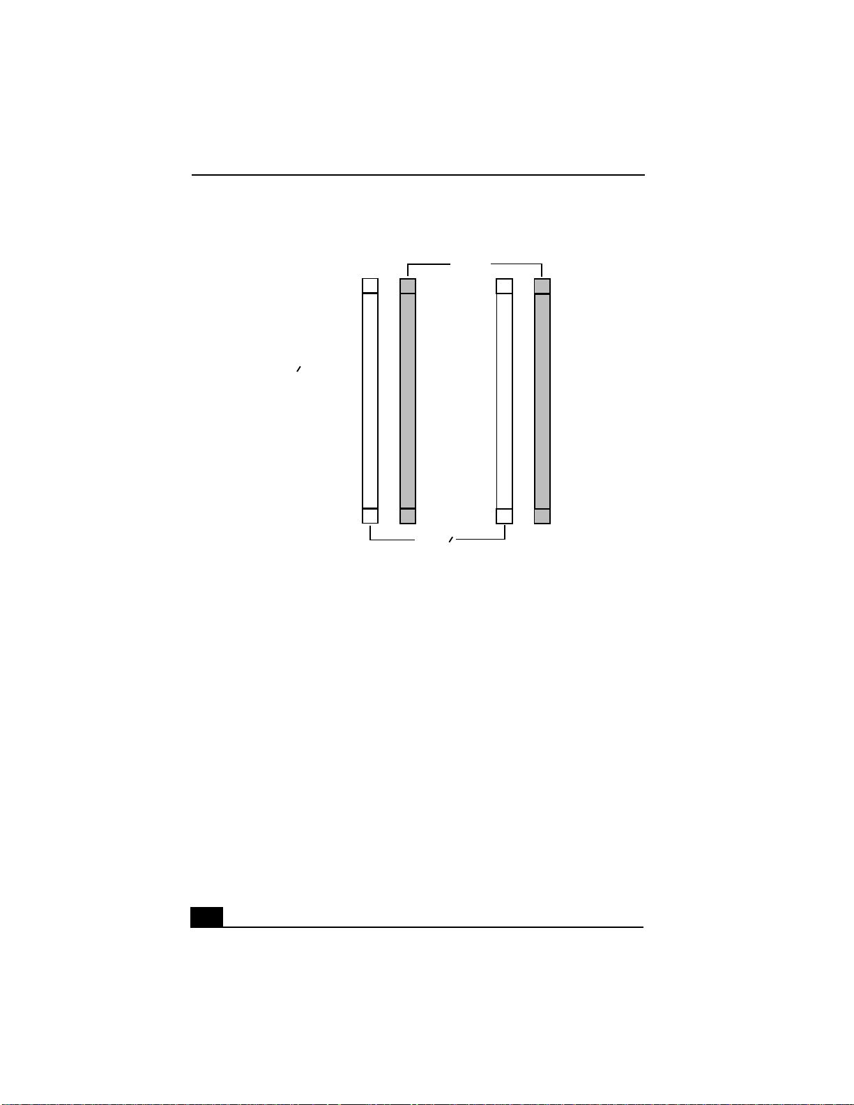
Interior RIMM Banks (Inside System)
Crimms (2) installed
in Bank 1 by default
64 MB (2) Rimms
installed in Bank 0
by default
SLOT 1
BANK
BANK
SLOT 1
1
SLOT 2
SLOT 2
0
6 Handle the RIMM only by the edges, and remove it from its anti-static
package.
7 Locate the notches on the bottom edge of the RIMM.
8 Align the module over the banks that originally held the CRIMMs.
9 Firmly insert the bottom edge of the RIMM into the bank.
10 Press evenly against the RIMM’s upper corners. The end latches snap into
position automatically.
6
Page 7
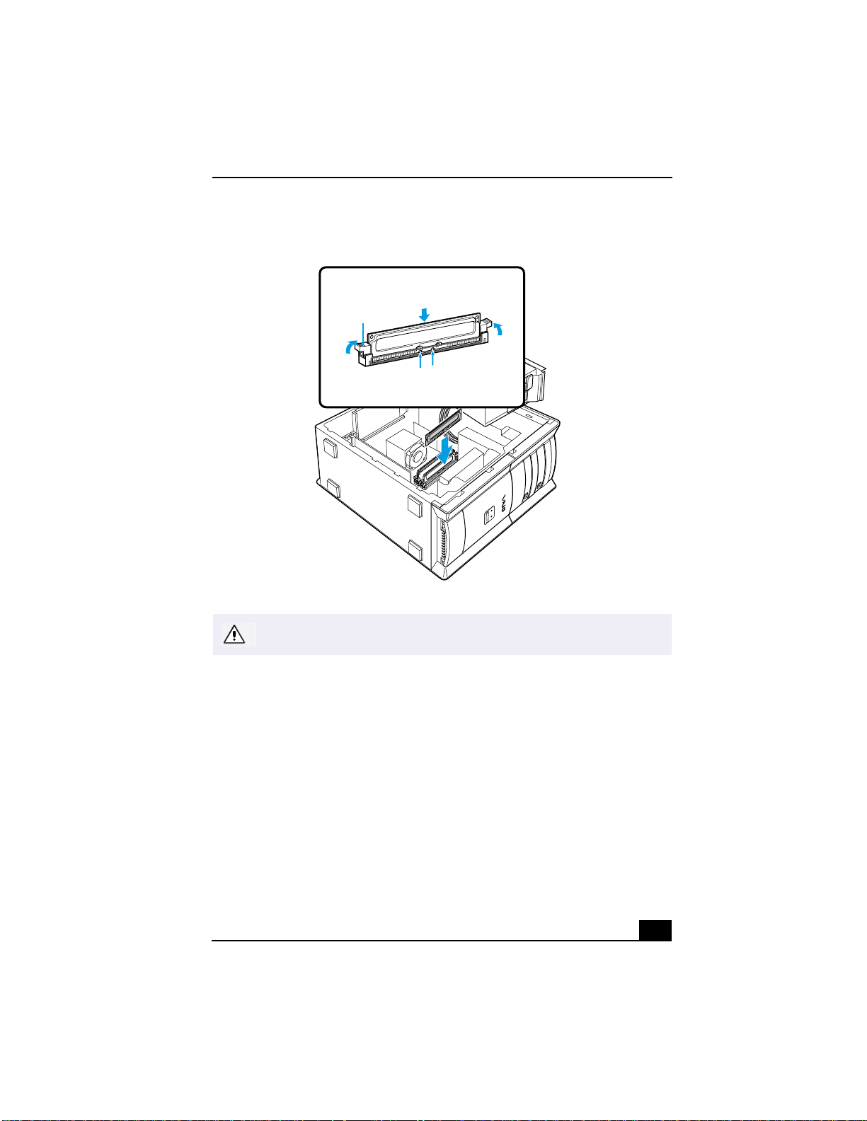
Installing Memory
Adding Memory
Latch
Edge Connectors
To avoid damaging the RIMM slot, move the RIMM slot tabs slightly outward
to relieve pressure. The module should click easily into place.
11 Reinstall the power supply and any add-on cards or components you
removed.
Reinstall the power supply by following these steps:
❑ Rotate the power supply to its original position and slide it into the
chassis until the tab snaps into position.
❑ Replace the screw that secures the power supply to the rear of the
chassis.
12 Replace the side cover as described in “Replacing the Side Cover.’’
7
Page 8
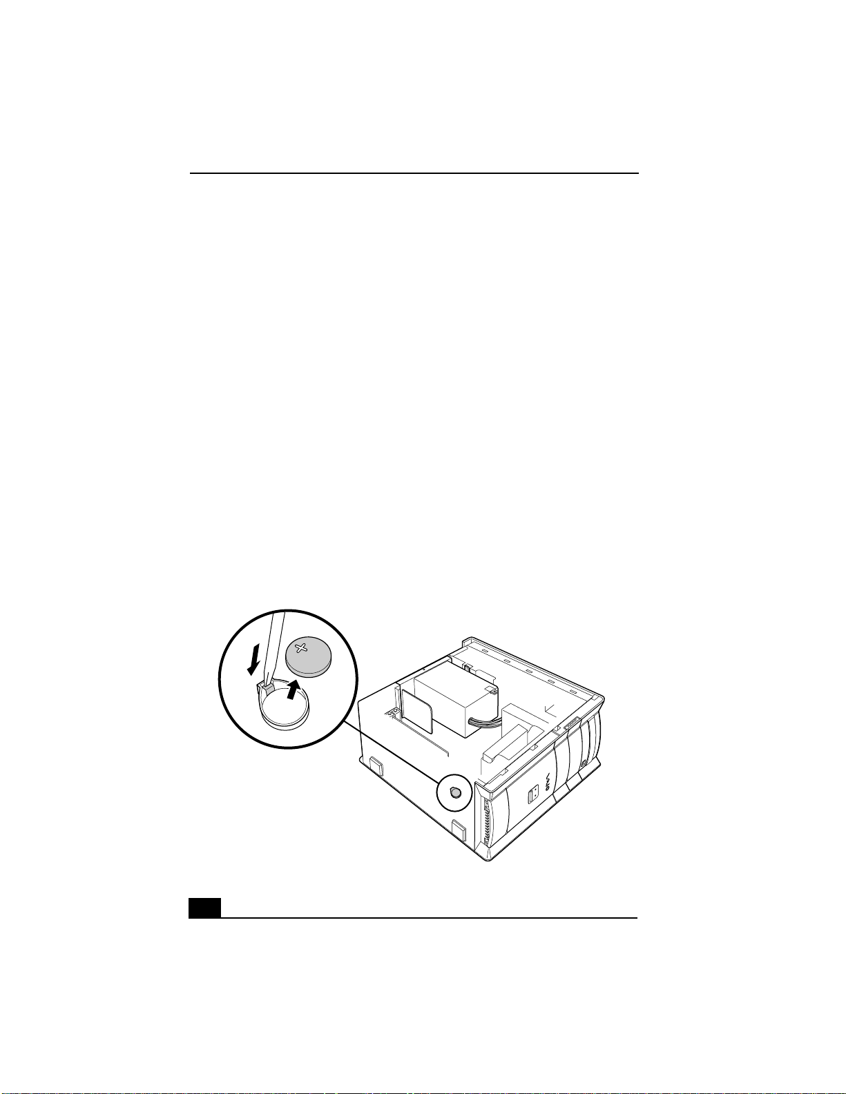
Replacing the Lithium Battery
The lithium battery starts to weaken after several years and the system settings,
such as the date and time stored in CMOS RAM, may become inaccurate. When
this occurs, you need to replace the lithium battery.
To replace the lithium battery
1 Write down any changes you have made to the settings in the BIOS Setup
utility. If you have not made any changes to the BIOS settings, proceed to
step 2.
2 Shut down your computer and turn off all peripheral devices, such as your
printer.
3 Unplug your computer and the peripheral devices.
4 Remove the side cover as described in “Removing the Side Cover.’’
5 If necessary , remove an y cables, add-on cards, or other components to access
the lithium battery.
6 Remove the old battery and install the new battery with the plus (+) side up.
Installing a Lithium Battery
8
Page 9
Replacing the Lithium Battery
7 Replace the side cover as described in “Replacing the Side Cover.’’
There is danger of the battery exploding if it is replaced incorrectly. You must
replace the battery only with a CR2032-type lithium battery. Discard used
batteries according to the instructions in the
User Guide
✍
The values stored in the CMOS memory are now reset to the factory default values.
You must run the Setup utility to reset the date, time, passwords, and other changes
you may have made to the BIOS settings. If you do not wish to customize your BIOS
settings, you do not need to run the Setup utility. If you simply wish to reset the date
and time, see Windows Help for instructions.
.
VAIO Digital Studio™ Computer
9
Page 10
Installing an Additional Hard Disk Drive
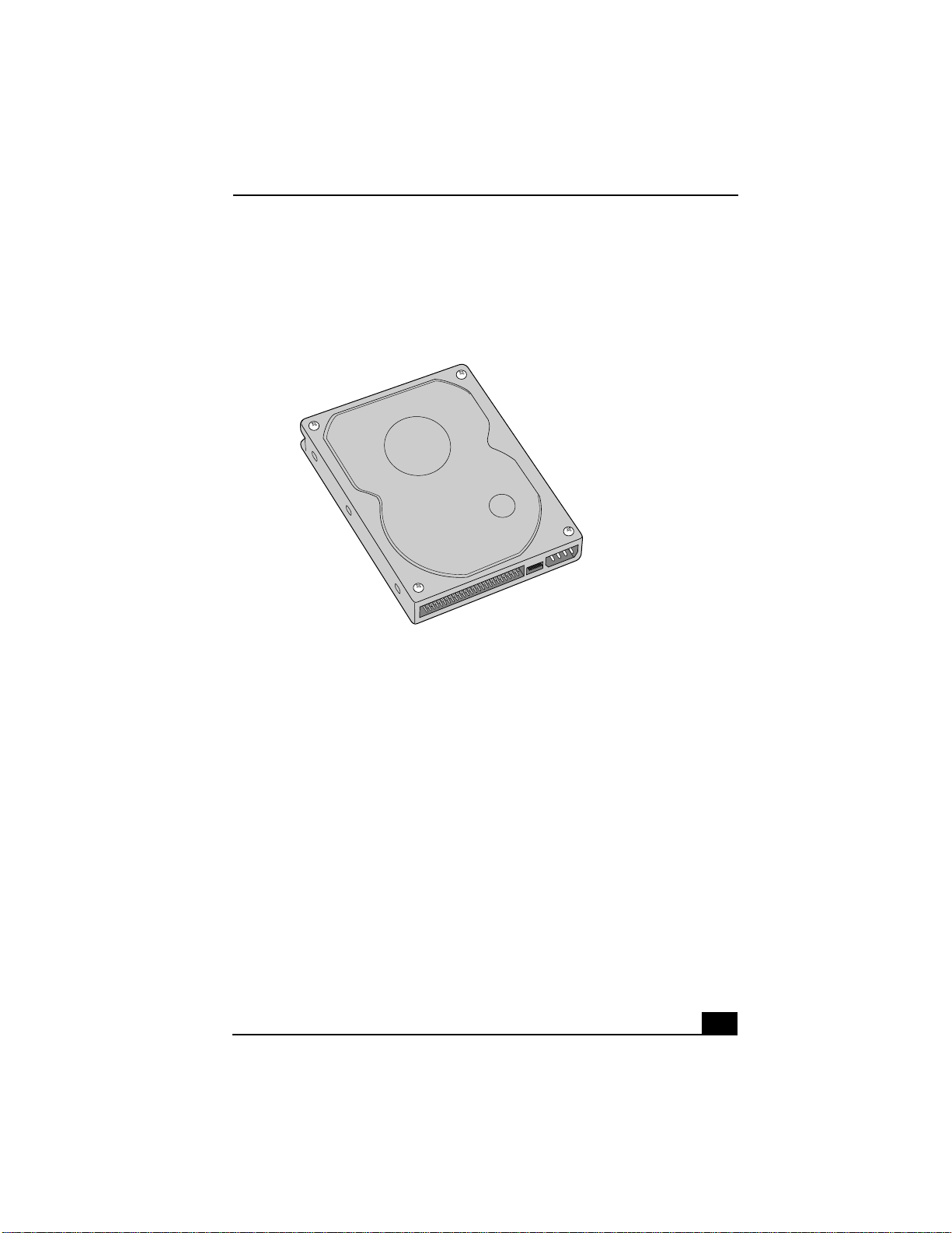
Your computer comes with an available internal bay to hold a second standard
3½-inch hard disk drive. Some models, such as Configure-to-Order (CTO)
systems, may already have a second hard disk drive installed. Your system can
support ATA-33, ATA-66, or ATA-100 hard disk drives. Sony recommends using
an ATA-100 hard disk drive to take full advantage of your system’s features. The
hard disk drive access light blinks when either internal drive is active.
For information on how to install additional drives, see the System Reference
Manual. You can download the System Reference Manual from the Sony Web
site at http://www.sony.com/pcsupport.
To prepare a startup disk
Before you add a second hard disk drive to your computer, Sony recommends
creating a startup floppy disk. To create a startup disk, insert a blank, formatted
floppy disk into your computer’s floppy disk drive and follow these steps:
1 From the Start menu, point to Settings, point to Control Panel, and then click
Add/Remove Programs.
2 Select the Startup Disk tab and then click Create Disk...
3 Click OK. Wait unti l the sy stem completes the startup disk and click OK to
close the dialog box.
4 From the Start menu, select Shutdown and choose the Shutdown option.
10
Before opening the system unit, save any open files, exit Windows, turn off
the power to the computer and all attached peripherals, and then unplug the
power cord.
Page 11
Installing an Additional Hard Disk Drive
To install an additional hard disk drive
1 Configure the jumpers on the new drive as a slave (see the manual that came
with your drive for configuration instructions).
Installing a Hard Drive
2 Remove the side cover as described in “Removing the Side Cover.’’
3 Detach the power and drive cables from the hard disk drive that is already
installed in your computer.
11
Page 12
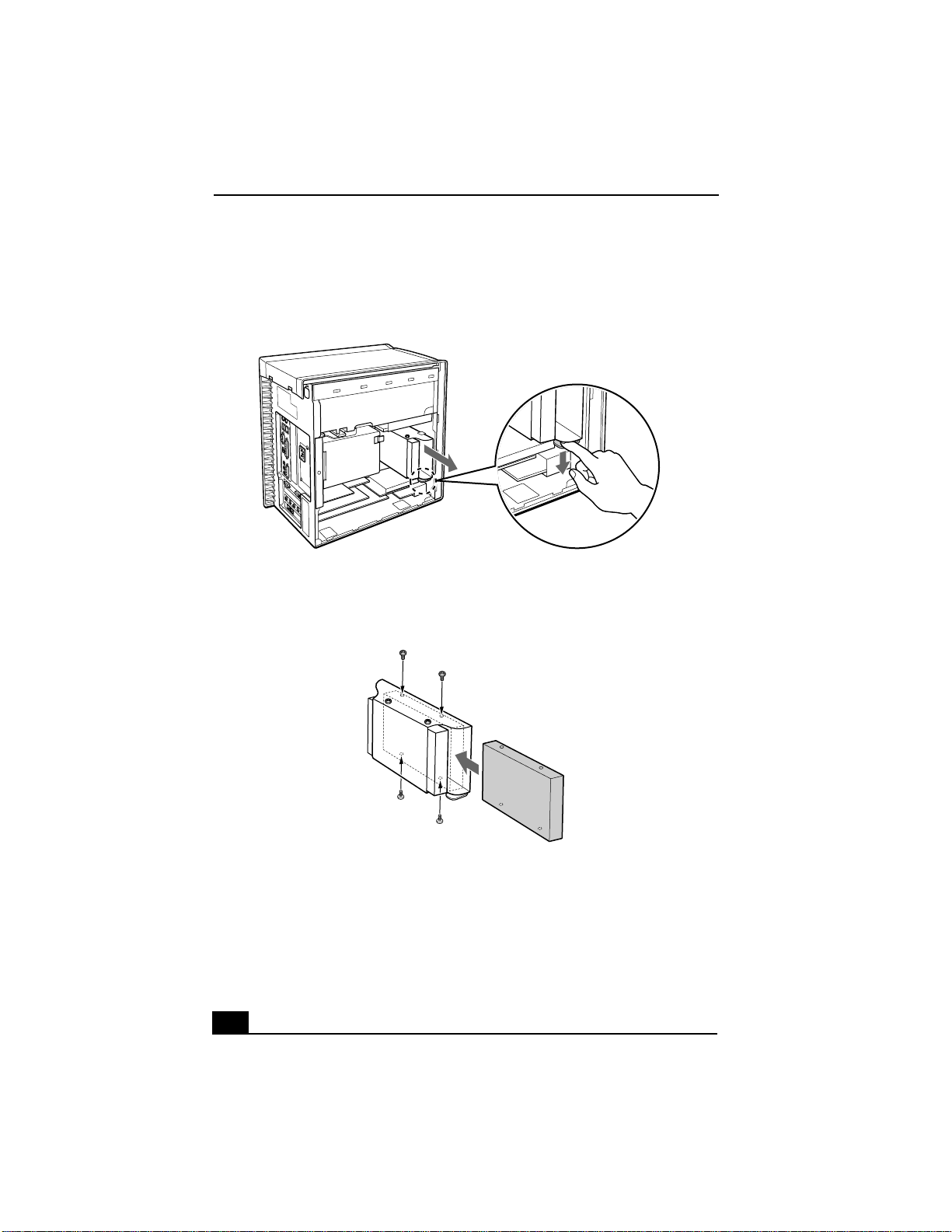
4 Unlock the drive holder from the chassis by pulling down on the tab located
at the bottom of the drive holder and then slide it out.
Removing the Drive Holder
5 Slide the new drive into the drive holder and align the holes on each side of
the drive bay.
Attaching the Drive Screws
6 Secure the drive to the drive holder using the two holes on each side of the
drive holder (scre ws are pro vided with the ne w dri ve). Do not o vertighten the
screws.
7 Align the drive holder with the slots on the inside of the chassis. Slide the
drive holder in completely and push up on the bottom tab to lock it in
position.
12
Page 13
Installing an Additional Hard Disk Drive
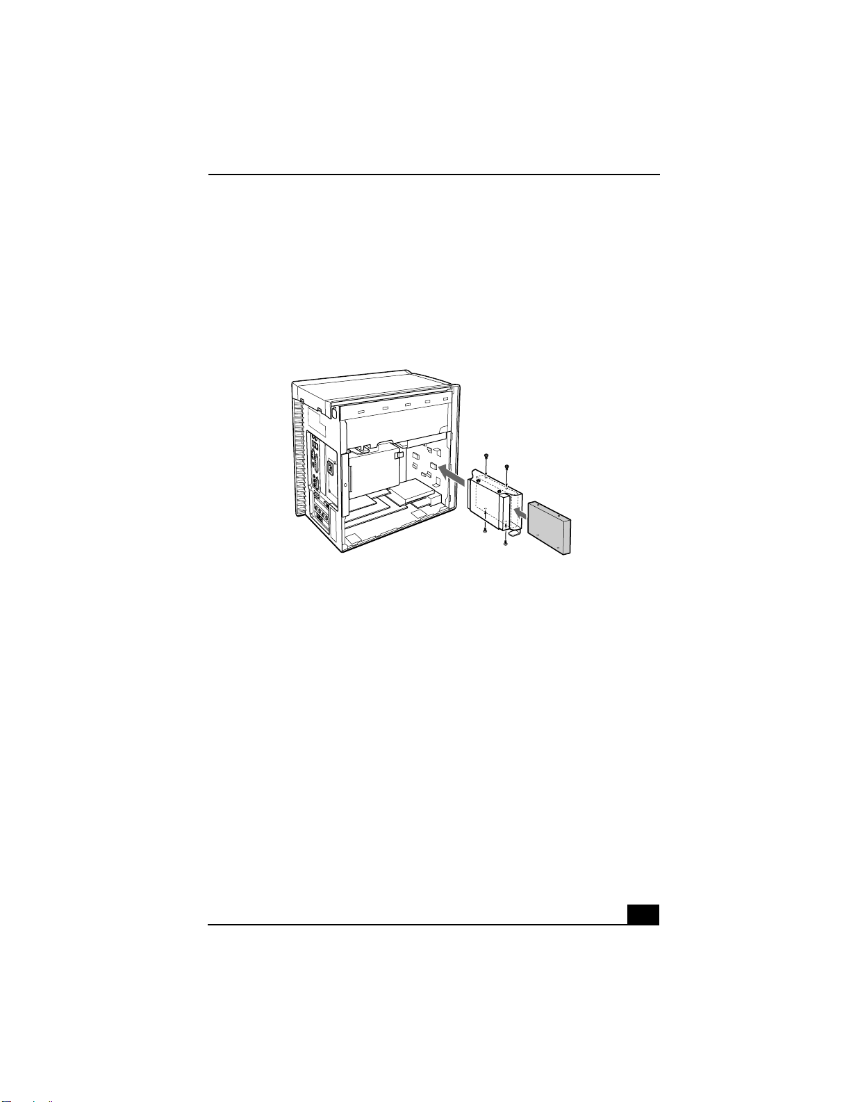
8 Connect the second drive connector to the new drive. Be sure to orient the
connector so that pin 1 on the red side of the ribbon cable is aligned with pin
1 of the new drive.
9 Connect the second power connector to the new drive (see the manual that
came with your drive for detailed instructions).
Replacing the Drive Holder
10 Replace the side cover as described in “Replacing the Side Cover.’’
11 Reconnect the power to your computer.
To set up the new hard disk drive with the startup disk
1 Insert the startup floppy disk into the floppy disk drive. Press the power
button and turn your computer on. A startup menu appears.
2 Select the option “4. Minimal Boot” to start your system. Wait until the
system completes startup.
3 Type in “fdisk” and press Enter.
4 Select the option “5. Change current fixed disk drive”.
5 Select the second hard disk drive by typing in “2” and press Enter.
6 Select the option “1. Create DOS partition or Logical DOS Drive” and press
Enter.
13
Page 14

7 Select the option “2. Create Extended DOS Partition” and press Enter.
8 Select “3. Create logical DOS Drive(s) in the Extended DOS Partition” and
press Enter.
9 Specify the maximum size for the partition and press Enter.
10 Remove the startup floppy disk from the floppy disk drive and restart your
computer.
11 From the Desktop, click on My Computer.
12 Right-click the icon for the new drive, Local Disk (E:). From the shortcut
menu, click Format. The Local Disk (E:) window appears.
13 Click Start. Wait until the system completes formatting of the new drive.
14 Turn off and then restart your computer.
15 From the Start menu, point to Programs, point to Giga Pocket, and then click
Video Explorer. The Video Explorer window appears.
16 Click Video Capsules from the menu bar and click Settings.
17 Select the “Set default Drive for saving” tab.
18 Move the E: drive to Saving destination and click OK.
14
Page 15
Replacing the Side Cover
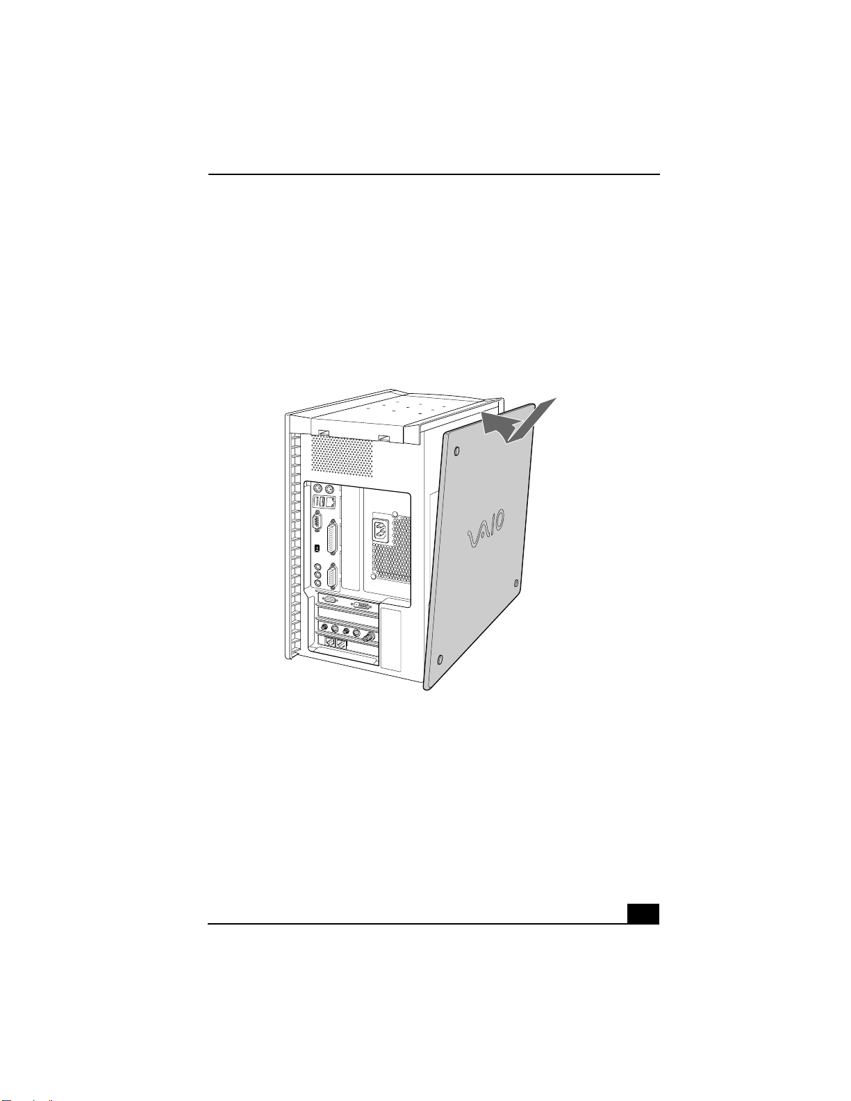
Replacing the Side Cover
To replace the side cover
1 Align the tabs on the side cover to the chassis rim.
2 Press the side cover firmly against the unit until it snaps into place.
Replacing the Side Cover
15
Page 16

16
 Loading...