

Vaillant VWL 57/5 IS, VWL 77/5 IS, VWL 75/5 AS, VWL 105/5 AS, VWL 125/5 AS Operating, Installation And Maintenance Instructions
...Page 1
en Operating instructions
en Installation and maintenance
instructions
Hydraulic station
VWL 57 ... 127/5 IS
Publisher/manufacturer
Vaillant GmbH
Berghauser Str. 40
D-42859 Remscheid
Tel. +492191 18 0
Fax +492191 18 2810
www.vaillant.de
Page 2

en Operating instructions ....................................... 1
en Installation and maintenance instructions...... 14
Page 3

Contents
0020257319_02 Hydraulic station Operating instructions 1
Operating instructions
Contents
1 Safety .................................................................... 2
1.1 Action-related warnings ......................................... 2
1.2 Intended use .......................................................... 2
1.3 General safety information .................................... 2
2 Notes on the documentation .............................. 4
2.1 Observing other applicable documents ................. 4
2.2 Storing documents................................................. 4
2.3 Validity of the instructions...................................... 4
3 Product description............................................. 4
3.1 Heat pump system ................................................. 4
3.2 Design of the product............................................. 4
3.3 Control elements.................................................... 4
3.4 Control panel ......................................................... 5
3.5 Description of the symbols .................................... 5
3.6 Functional description of buttons........................... 5
3.7 Type designation and serial number ..................... 5
3.8 CE marking ............................................................ 6
3.9 Fluorinated greenhouse gases .............................. 6
3.10 Safety devices ....................................................... 6
4 Operation.............................................................. 6
4.1 Basic display.......................................................... 6
4.2 Operating concept ................................................. 6
4.3 Menu display.......................................................... 6
4.4 Starting up the product .......................................... 7
4.5 Checking the filling pressure in the heat pump
circuit ..................................................................... 8
4.6 Setting the heating flow temperature..................... 8
4.7 Setting the domestic hot water temperature .......... 8
4.8 Switching off the product's functions ..................... 8
5 Care and maintenance ........................................ 8
5.1 Caring for the product............................................ 8
5.2 Maintenance .......................................................... 9
5.3 Reading maintenance messages .......................... 9
5.4 Checking the system pressure .............................. 9
6 Troubleshooting .................................................. 9
6.1 Reading fault messages ........................................ 9
6.2 Detecting and eliminating faults............................. 9
7 Decommissioning................................................ 9
7.1 Temporarily decommissioning the product............ 9
7.2 Permanently decommissioning the product........... 9
8 Recycling and disposal ....................................... 9
8.1 Disposing of the product and the accessories....... 9
8.2 Arranging disposal of refrigerant ......................... 10
9 Guarantee and customer service..................... 10
9.1 Guarantee............................................................ 10
Appendix ............................................................................11
A Troubleshooting ................................................ 11
B Overview of the end user operating level ....... 11
Index ...................................................................................13
Page 4
1 Safety
2 Operating instructions Hydraulic station 0020257319_02
1 Safety
1.1 Action-related warnings
Classification of action-related warnings
The action-related warnings are classified in
accordance with the severity of the possible
danger using the following warning signs and
signal words:
Warning symbols and signal words
Danger!
Imminent danger to life or risk of
severe personal injury
Danger!
Risk of death from electric shock
Warning.
Risk of minor personal injury
Caution.
Risk of material or environmental
damage
1.2 Intended use
There is a risk of injury or death to the user or
others, or of damage to the product and other
property in the event of improper use or use
for which it is not intended.
The product is the indoor unit of an air-towater heat pump with split construction.
The product uses the outdoor air as a heat
source and can be used to heat a residential
building and for domestic hot water generation.
The product is intended exclusively for domestic use.
The intended use only allows for these
product combinations:
Outdoor unit Indoor unit
VWL ..5/5 AS ... VWL ..8/5 IS ...
VWL ..7/5 IS ...
Intended use includes the following:
– observance of the operating instructions
included for the product and any other
installation components
– compliance with all inspection and main-
tenance conditions listed in the instructions.
This product can be used by children aged
from 8 years and above and persons with
reduced physical, sensory or mental capabilities or lack of experience and knowledge if
they have been given supervision or instruction concerning use of the product in a safe
way and understand the hazards involved.
Children must not play with the product.
Cleaning and user maintenance work must
not be carried out by children unless they are
supervised.
Any other use that is not specified in these
instructions, or use beyond that specified in
this document, shall be considered improper
use. Any direct commercial or industrial use
is also deemed to be improper.
Caution.
Improper use of any kind is prohibited.
1.3 General safety information
1.3.1 Danger caused by improper
operation
Improper operation may present a danger to
you and others, and cause material damage.
▶ Carefully read the enclosed instructions
and all other applicable documents, particularly the "Safety" section and the warnings.
▶ Only carry out the activities for which in-
structions are provided in these operating
instructions.
1.3.2 Risk of death due to changes to the
product or the product environment
▶ Never remove, bridge or block the safety
devices.
▶ Do not tamper with any of the safety
devices.
▶ Do not damage or remove any tamper-
proof seals on components.
▶ Do not make any changes:
– The product itself
– The water and electricity supply lines
– to the expansion relief valve
– to the drain pipework
– to constructional conditions that may
affect the operational reliability of the
product
Page 5

Safety 1
0020257319_02 Hydraulic station Operating instructions 3
1.3.3 Risk of injury and material damage
due to maintenance and repairs
carried out incorrectly or not carried
out at all
▶ Never attempt to carry out maintenance
work or repairs on your product yourself.
▶ Faults and damage should be immediately
rectified by a competent person.
▶ Adhere to the maintenance intervals spe-
cified.
1.3.4 Risk of material damage caused by
frost
▶ Ensure that the heating installation always
remains in operation during freezing conditions and that all rooms are sufficiently
heated.
▶ If you cannot ensure the operation, have a
competent person drain the heating installation.
1.3.5 Risk of injury from freezing caused
by touching refrigerant
The product is delivered with an operational
filling of R410A refrigerant. Escaping refrigerant may cause freezing if the exit point is
touched.
▶ If refrigerant escapes, do not touch any
components of the product.
▶ Do not inhale any vapours or gases that
escape from the refrigerant circuit as a
result of leaks.
▶ Avoid skin or eye contact with the refriger-
ant.
▶ In the event of skin or eye contact with the
refrigerant, seek medical advice.
1.3.6 Risk of chemical burns caused by
brine fluid
The brine fluid ethylene glycol is harmful to
health.
▶ Avoid contact with the skin and eyes.
▶ Always wear gloves and protective
goggles.
▶ Do not inhale or swallow.
▶ Observe the safety data sheet that accom-
panies the brine fluid.
1.3.7 Risk of injury from burns caused by
touching refrigerant pipes
The refrigerant pipes between the outdoor
unit and the indoor unit may become extremely hot during operation. There is a risk
of burns.
▶ Do not touch any uninsulated refrigerant
pipes.
1.3.8 Risk of malfunctions caused by
incorrect power supply
The power supply must remain within the
specified limits so that the product does not
malfunction:
– Single-phase: 230 V (+10/-15%), 50 Hz
– Three-phase: 400 V (+10/-15%), 50 Hz
1.3.9 Risk of environmental damage
caused by escaping refrigerant
The product contains the refrigerant R410A.
This refrigerant must not be allowed to escape into the atmosphere. R410A is a fluorinated greenhouse gas covered by the Kyoto
Protocol, with a GWP of 2088 (GWP = Global
Warming Potential). If this gas escapes into
the atmosphere, its impact is 2088 times
greater than the natural greenhouse gas CO2.
Before the product is disposed of, the refrigerant that is contained in it must be completely drained into a suitable vessel so that
it can then be recycled or disposed of in accordance with regulations.
▶ Ensure that only an officially certified com-
petent person with appropriate protective
equipment carries out installation or maintenance work or any other form of intervention on the refrigerant circuit.
▶ Arrange for the refrigerant that is contained
in the product to be recycled or disposed
of by a certified competent person in accordance with the regulations.
Page 6
2 Notes on the documentation
4 Operating instructions Hydraulic station 0020257319_02
2 Notes on the documentation
2.1 Observing other applicable documents
▶ You must observe all operating instructions enclosed with
the system components.
2.2 Storing documents
▶ Keep this manual and all other applicable documents
safe for future use.
2.3 Validity of the instructions
These instructions apply only to:
Product Outdoor unit
VWL 57/5 IS VWL 35/5 AS
VWL 55/5 AS
VWL 77/5 IS VWL 75/5 AS
VWL 127/5 IS VWL 105/5 AS
VWL 125/5 AS
3 Product description
3.1 Heat pump system
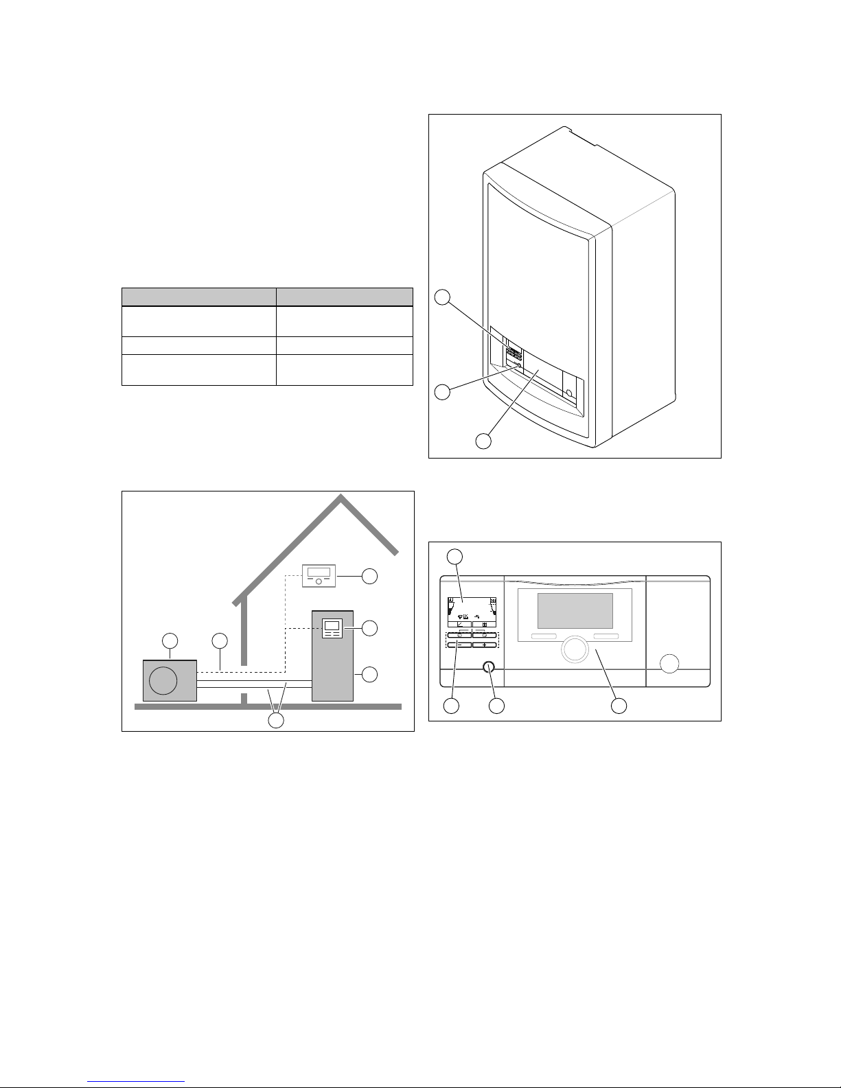
Design of a typical heat pump system with split technology:
1 2
4
3
5
6
1 Heat pump | Outdoor
unit
2 eBUS line
3 System control (op-
tional)
4 Control for the indoor
unit
5 Heat pump | Indoor unit
6 Refrigerant circuit
3.2 Design of the product
2
3
1
1 Optional installation site
for the system control
2 Reset button
3 Control elements
3.3 Control elements
reset
120
kWh/d
E
4
3 2 1
1 System control (optional
accessory)
2 Reset button
3 Control elements
4 Display
Page 7
Product description 3
0020257319_02 Hydraulic station Operating instructions 5
3.4 Control panel
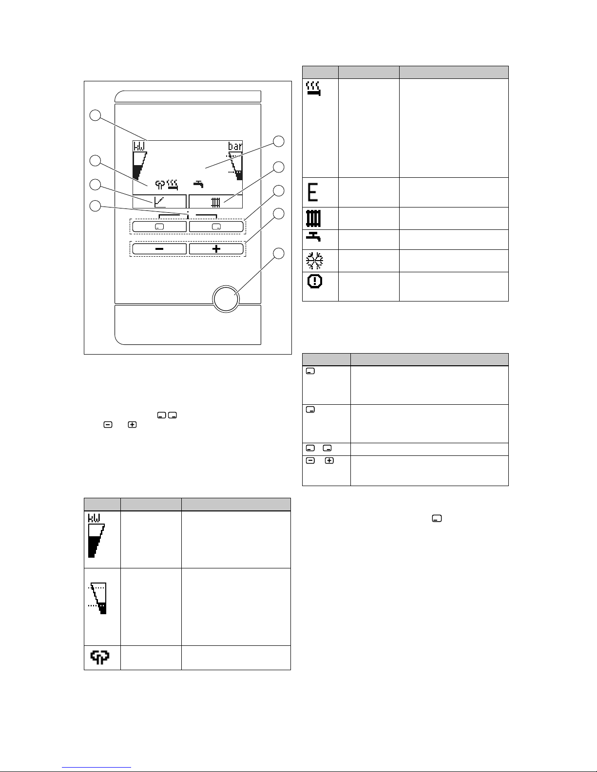
120
kWh/d
E
reset
1
2
3
4
6
7
8
9
5
1 Displays the daily envir-
onmental energy yield
2 Display of the current
assignment of the righthand selection button
3 Left- and right-hand
selection buttons
4
and button
5 Reset button
6 Access to the menu for
additional information
7 Display of the current
configuration of the lefthand selection button
8 Displays the symbols
for the current operating
status of the heat pump
9 Display
3.5 Description of the symbols
If you do not press any buttons within one minute, the light
goes out.
Symbol Meaning Explanation
Compressor
power
– Not filled: Compressor not in
operation
– Partially filled: Compressor in
operation. Partial load mode.
– Fully filled: Compressor in
operation. Full load mode.
bar
Filling pressure
in the heating
circuit
The dashed lines show the
permitted range.
– Displayed statically: Filling
pressure in the permitted
range
– Displayed flashing: Filling
pressure outside of the
permitted range
Noise reduction
mode
– Operation with reduced
sound emissions
Symbol Meaning Explanation
Electric back-up
heater
– Displayed flashing: Electric
back-up heater in operation
– Displayed together with the
"Heating mode" symbol:
Electric back-up heater
active for heating mode
– Displayed together with
the "Domestic hot water
generation" symbol: Electric
back-up heater active for
domestic hot water mode
eco mode – Energy-saving domestic hot
water mode
Heating mode – Heating mode active
Domestic hot
water generation
– Domestic hot water mode
active
Cooling mode – Cooling mode active
F. X X X
Fault condition – Appears instead of the basic
display, may be an explanatory plain text display
3.6 Functional description of buttons
The two selection buttons are soft keys, meaning that they
can be assigned different functions.
Button Meaning
– Cancelling the change to a set value or
activating an operating mode
– Calling up a higher selection level in the
menu
– Confirming a set value or activating an oper-
ating mode
– Calling up a lower selection level in the
menu
+
Calling up the additional functions
or
– Navigating between individual menu items
– Increasing or decreasing the chosen set
value
Adjustable values flash in the display.
You must always confirm a change to a value. Only then is
the new setting saved. You can press to cancel a process at any time. If you do not press any buttons for longer
than 15 minutes, the display returns to the basic display.
3.7 Type designation and serial number
The type designation and serial number are on the data
plate.
Page 8
4 Operation
6 Operating instructions Hydraulic station 0020257319_02
3.8 CE marking
The CE marking shows that the products comply with the
basic requirements of the applicable directives as stated on
the data plate.
The declaration of conformity can be viewed at the manufacturer's site.
3.9 Fluorinated greenhouse gases
The product contains fluorinated greenhouse gases in a hermetically sealed device. As specified in the technical specifications from the manufacturer, the tested leak rate for the
electrical switchgear is less than 0.1% per year.
3.10 Safety devices
3.10.1 Frost protection function
The frost protection function for the system is controlled using the product itself or using the optional system control. If
the system control fails, the product guarantees limited frost
protection for the heating circuit.
3.10.2 Low-water pressure protection
This function continuously monitors the pressure of the heating water in order to prevent a possible loss of heating water.
3.10.3 Freeze protection
This function prevents the outdoor unit's evaporator from
freezing when the heat source temperature drops below a
certain value.
The outlet temperature of the heat source is constantly
measured. If the outlet temperature of the heat source falls
below a certain value, the compressor temporarily switches
off and displays a status message. If this fault occurs three
times in a row, it is switched off and a fault message is
displayed.
3.10.4 Pump blocking protection
This function prevents the pumps for heating water from
sticking. The pumps, which were out of operation for
23 hours, are switched on for 10–20 seconds, one after the
other.
3.10.5 Hot gas thermostat in the refrigerant circuit
The hot gas thermostat shuts down the heat pump if the temperature in the refrigerant circuit is too high. Following a waiting period, the heat pump attempts to start once more. After
three failed start attempts in succession, a fault message is
displayed.
– Max. refrigerant circuit temperature: 135 ℃
– Waiting period: 5 minutes (after the first occurrence)
– Waiting period: 30 minutes
(after the second and every further occurrence)
The fault counter is reset if both of the following conditions
are met:
– Heat requirement without switching off prematurely
– 60 minutes of uninterrupted operation
3.10.6 Safety cut-out (SCO) in the heating circuit
If the temperature in the heating circuit of the internal electric back-up heater exceeds the maximum temperature, the
safety cut-out shuts down the electric back-up heater as a
securing measure. After it is triggered, the safety cut-out
must be replaced.
– Max. heating circuit temperature: 95 ℃
4 Operation
4.1 Basic display
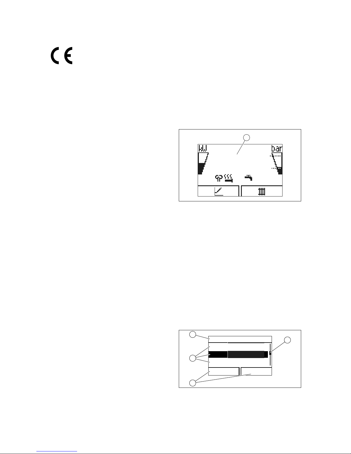
120
kWh/d
E
1
The displays shows the basic display with the current status
of the product. The daily energy yield (1) is displayed in the
centre of the display.
If you press a selection button, the activated function is displayed in the display.
As soon as a fault message is present, the basic displays
switches to the fault message.
4.2 Operating concept
The product has two operating levels.
The operating level for the end user shows the most important information and offers setting options which do not require any special prior knowledge.
The operating level for the competent person is reserved for
the competent person and is protected by a code.
You can find further information in the operating instructions
for the indoor unit.
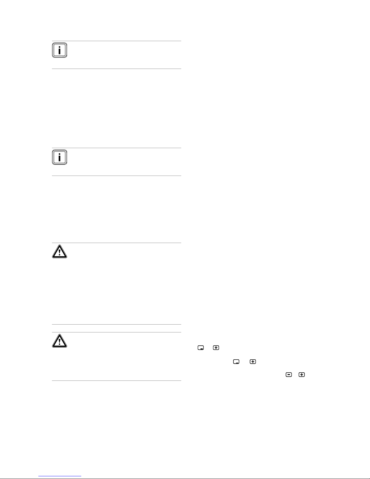
4.3 Menu display
Xxxx
Xxxxxxxxxxx
Xxxx Xxxxxxx
Xxxxxxxxxx
xxxxxx Xxxxxxx
1
4
3
2
1 Scroll bar
2 Current assignment of
the selection buttons
3 Selection level list
entries
4 Selection level
Page 9
Operation 4
0020257319_02 Hydraulic station Operating instructions 7
Note
Path details at the start of a section specify how to
access this function, e.g. Menu ¬ Information ¬
Contact data.
4.4 Starting up the product
4.4.1 Opening the isolator devices
1. Ask the competent person who installed the product to
explain to you where these isolator devices are located
and how to handle them.
2. If installed, open the service valves in the heating installation's flow and return.
3. Open the cold-water isolation valve.
4.4.2 Switching on the product
Note
The product does not have an on/off switch. The
product is switched on and ready for operation as
soon as it is connected to the power grid.
1. Ensure that the product casing is properly installed.
2. Use the partition that is installed on-site (e.g. fuses or
power switches) to switch on the product.
◁ The "basic display" appears in the product's operat-
ing display.
◁ The basic display appears on the system control
display.
4.4.3 Adjusting the target cylinder temperature
Danger!
Risk of death from legionella.
Legionella multiply at temperatures below
60 °C.
▶ Have a competent person inform you
about the measures that should be taken
to protect against Legionella in your installation.
▶ Do not set any water temperatures below
60 °C without consulting the competent
person first.
Danger!
Risk of death from legionella!
If you decrease the cylinder temperature, the
risk of legionella spreading increases.
▶ Activate the anti-legionella times in the
system control and set them.
In order to achieve energy-efficient domestic hot water generation predominantly from the energy extracted from the
environment, the factory setting for the desired domestic hot
water temperature must be adjusted on the system control.
▶ To do this, adjust the target cylinder temperature (De-
sired DHW circuit temperature) to between 50 and
55 °C.
◁ Depending on the source of energy obtained from the
environment, domestic hot water outlet temperatures
of between 50 and 55 °C are reached.
4.4.4 Yield indicator
You can use this function to display the environmental
energy yield as a cumulative value for a period of a day,
a month and the total for the heating, domestic hot water
generation and cooling modes.
You can displays the working figure for a period of a month
and the total for the heating and domestic hot water generation modes. The working figure is the ratio of thermal energy
generated to the operating current used. Monthly values may
vary considerably since, for example, in the summer only
domestic hot water generation is used. A large number of
factors influence this estimate, e.g. the type of heating installation (direct heating mode = low flow temperature or indirect heating mode via buffer cylinder = high flow temperature). This figure may therefore deviate by up to 20%.
The working figures only record the power consumption of
internal components, not of external components such as
external heating circuit pumps, valves, etc.
4.4.5 Displaying the Live Monitor
Menu → Live Monitor
You can use the Live Monitor to view the current status of
the product.
4.4.6 Displaying the building circuit pressure
Menu → Live Monitor→ Building circuit pressure
You can use this function to display the current filling pressure in the heating installation.
4.4.7 Reading the operating statistics
Menu → Information → Heating op. hours
Menu → Information → DHW operating hours
Menu → Information → Cooling op. hours
Menu → Information → Total operating hours
You can use this function to display the operating hours
for heating mode, for domestic hot water mode, for cooling
mode and for overall operation.
4.4.8 Setting the language
1. Select OK twice to confirm the set language.
2. If you want to set another language, press and hold
and at the same time.
3. Also press the reset button for a short time.
4. Press and hold
and until the display shows the
language setting.
5. Select the required language by pressing
or .
6. Press (OK) to confirm your selection.
7. Once you have set the correct language, press (OK)
again to confirm this.
4.4.9 Set display contrast
Menu → Basic settings → Display contrast
▶ You can set the contrast here.
Page 10
5 Care and maintenance
8 Operating instructions Hydraulic station 0020257319_02
4.4.10 Serial number and article number
Menu → Information → Serial number
The product's serial number is displayed.
The article number is found in the second line of the serial
number.
4.4.11 Contact details for the competent person
Menu → Information → Contact data Phone number
If the competent person has entered their telephone number
during the installation, you can read it here.
4.5 Checking the filling pressure in the heat
pump circuit
Note
To avoid operating the installation with insufficient
water volume and to prevent possible damage
associated with this, the product is fitted with a
pressure sensor and a digital pressure display.
To ensure that the heating installation operates
properly, the filling pressure must be between 0.1
MPa and 0.15 MPa (1.0 bar and 1.5 bar) when the
heating installation condition is cold.
If the heating installation extends over several
storeys, a higher filling pressure may be required
for the heating installation. Ask a competent person for details.
Note
If the pressure falls below 0.07 MPa (0.7 bar),
message M32 appears.
If the pressure rises above 0.07 MPa (0.7 bar),
message M32 goes out.
In addition, the symbol is displayed after approx. one minute.
If the filling pressure of the heating installation
falls below 0.05 MPa (0.5 bar) for longer than one
minute, fault message F.22 and the current filling
pressure appear alternately in the display.
If the blocking time has elapsed or if the filling
pressure of the heating installation rises above
0.05 MPa (0.5 bar), fault message F.22 goes out.
1. Use Menu Live Monitor Water pressure to display the
filling pressure in the heat pump circuit.
2. If the pressure drops frequently, identify and eliminate
the reason for the pressure loss of heating water. Inform a competent person of this.
4.6 Setting the heating flow temperature
▶ See the table in the appendix.
Overview of the end user operating level
4.7 Setting the domestic hot water temperature
▶ See the table in the appendix.
Overview of the end user operating level
4.8 Switching off the product's functions
4.8.1 Frost protection function
Caution.
Risk of material damage due to frost.
The frost protection function cannot guarantee circulation through the entire heating installation. Under certain circumstances, there
is therefore a risk of frost to certain parts of
the heating installation, which may cause
damage.
▶ During a period of frost, ensure that the
heating installation remains in operation
and that all rooms are sufficiently heated,
even when you are away.
To ensure that the frost protection devices are permanently
ready for operation, you must leave the system switched on.
Another way to protect the heating installation and the
product from frost for very long switch-off periods is to drain
them completely.
▶ Consult a competent person about this.
4.8.2 Switching off heating mode (Summer mode)
▶ Observe the instructions for the system control.
4.8.3 Switching off domestic hot water generation
▶ Observe the instructions for the system control.
5 Care and maintenance
5.1 Caring for the product
▶ Clean the casing with a damp cloth and a little solvent-
free soap.
▶ Do not use sprays, scouring agents, detergents, solvents
or cleaning agents that contain chlorine.
Page 11

Troubleshooting 6
0020257319_02 Hydraulic station Operating instructions 9
5.2 Maintenance
Applicability: Except Great Britain
An annual inspection and biennial maintenance of the
product carried out by a competent person is a prerequisite
for ensuring that the product is permanently ready and
safe for operation, reliable, and has a long service life. The
inspection may require maintenance to be carried out earlier,
depending on the results.
Applicability: Great Britain
An annual inspection of the product carried out by a competent person is a prerequisite for ensuring that the product is
permanently ready and safe for operation, reliable, and has a
long working life.
5.3 Reading maintenance messages
If the
symbol is shown in the display, the product requires
maintenance work or the product is in restricted mode (comfort protection). The product is not in fault mode; it continues
to operate.
▶ Consult a competent person.
Condition: Lhm. 37 is displayed
The product is in Comfort protection mode. The product has
detected a permanent fault and continues to run with restricted comfort.
5.4 Checking the system pressure
1. Check the filling pressure of the heating installation
every day for a week after initial start-up and maintenance work, and then twice a year.
– Min. heating circuit operating pressure: ≥ 0.07 MPa
(≥ 0.70 bar)
2. If the filling pressure is too low, inform your competent
person so that they can refill the heating water.
6 Troubleshooting
6.1 Reading fault messages
Fault messages have priority over all other displays and are
shown on the display instead of the basic display. If several
faults occur at the same time, these are displayed alternately
for two seconds each.
Depending on the type of fault, the system can work in limp
home mode in order to maintain the heating mode or domestic hot water generation.
F.723 Building circuit: Pressure too low
If the filling pressure falls below the minimum pressure, the
heat pump will be switched off automatically.
▶ Inform your competent person so that he can top up the
heating water.
F.1120 Heating rod: Phase failure
If the electric back-up heater is defective, the anti-legionella
function is not guaranteed.
▶ Inform your competent person so that they can rectify the
fault and reset the internal circuit breaker.
6.2 Detecting and eliminating faults
▶ If problems occur whilst operating the product, you can
carry out certain checks with the aid of the table.
Troubleshooting (→ Page 11)
▶ If the product is not functioning correctly, even though
you have checked the points listed in the table, contact a
competent person.
7 Decommissioning
7.1 Temporarily decommissioning the product
▶ Use the partition that is installed on-site (e.g. fuses
or power switches) to disconnect the product from the
power supply.
7.2 Permanently decommissioning the product
▶ Have a competent person permanently decommission
and dispose of the product.
8 Recycling and disposal
▶ The competent person who installed your product is re-
sponsible for the disposal of the packaging.
If the product is labelled with this mark:
▶ In this case, do not dispose of the product with the
household waste.
▶ Instead, hand in the product to a collection centre for
waste electrical or electronic equipment.
If the product contains batteries that are labelled with
this mark, these batteries may contain substances that are
hazardous to human health and the environment.
▶ In this case, dispose of the batteries at a collection point
for batteries.
8.1 Disposing of the product and the
accessories
Do not dispose of the product or the accessories with household waste.
▶ Ensure that the product and all accessories are disposed
of properly.
▶ Observe all valid regulations.
Page 12

9 Guarantee and customer service
10 Operating instructions Hydraulic station 0020257319_02
8.2 Arranging disposal of refrigerant
The product is filled with R410A refrigerant which must not
be released into the atmosphere.
▶ Refrigerant must only be disposed of by a qualified com-
petent person.
9 Guarantee and customer service
9.1 Guarantee
Applicability: Great Britain
Vaillant provides a full parts and labour guarantee for this
appliance for the duration as shown on the enclosed registration card which must be fully completed and returned
within 30 days of installation. All appliances must be installed
by a suitably competent person fully conversant and in accordance with all current regulations applicable to the appliance type installation. In the case of gas appliances the
Gas Safety (Installation and Use) Regulations 1998, and the
manufacturer’s instructions. In the UK competent persons
approved at the time by the Health and Safety Executive undertake the work in compliance with safe and satisfactory
standards. Installers should also be fully conversant with and
competent with all necessary electrical and building regulations that may apply to the installation.
In addition all unvented domestic hot water cylinders must
be installed by a competent person to the prevailing building regulations at the time of installation (G3). All appliances
shall be fully commissioned in accordance with our installation manual and Benchmark commissioning check list (this
will be included within the installation manual). These must
be signed and given to the user for safe keeping during the
hand over process. Installers should also at this time advise
the user of the annual servicing requirements and advise of
appropriate service agreement.
Terms and conditions do apply to the guarantee, details of
which can be found on the registration card included with this
appliance. In order to qualify for guarantee after one year the
appliance must be serviced in accordance with our installation manual servicing instructions. The benchmark service
history should be completed. Note - all costs associated with
this service are excluded from this guarantee.
Failure to install and commission this appliance in compliance with the manufacturer’s instructions will invalidate the
guarantee (this does not affect the customer’s statutory
rights).
Page 13
Appendix
0020257319_02 Hydraulic station Operating instructions 11
Appendix
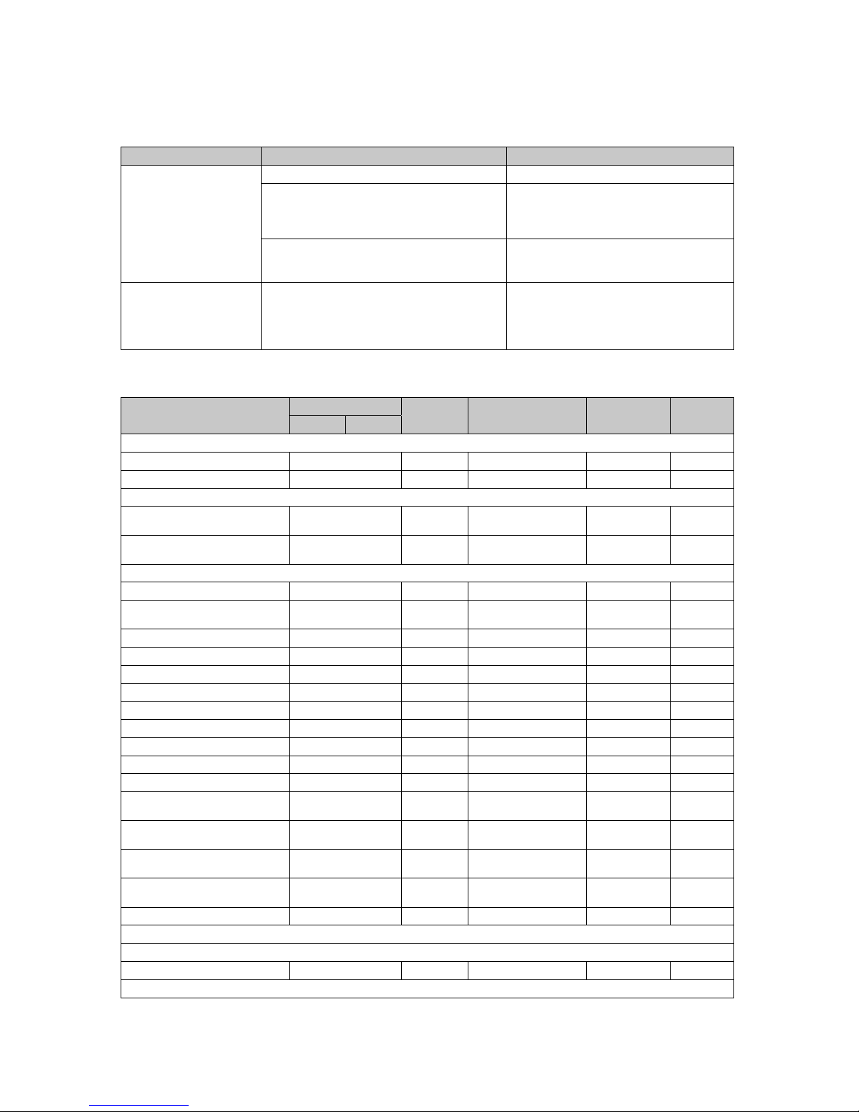
A Troubleshooting
Problem Possible cause Remedy
No domestic hot water, heating remains cold; product
does not start up
Building power supply switched off Switch on building power supply
Domestic hot water or heating set to "off"/domestic
hot water temperature or target temperature set too
low
Ensure that domestic hot water mode and/or
heating mode is activated in the system control.
Set the domestic hot water temperature in the
system control to the required value.
Air in the heating installation Purging the radiators
If the problem occurs again: Inform the competent person
Domestic hot water mode
without any problems; heating does not start
No heat requirement via the control Check the timer programme on the control and
correct if necessary
Check the room temperature and, if required,
correct the target room temperature (→ Control
operating instructions)
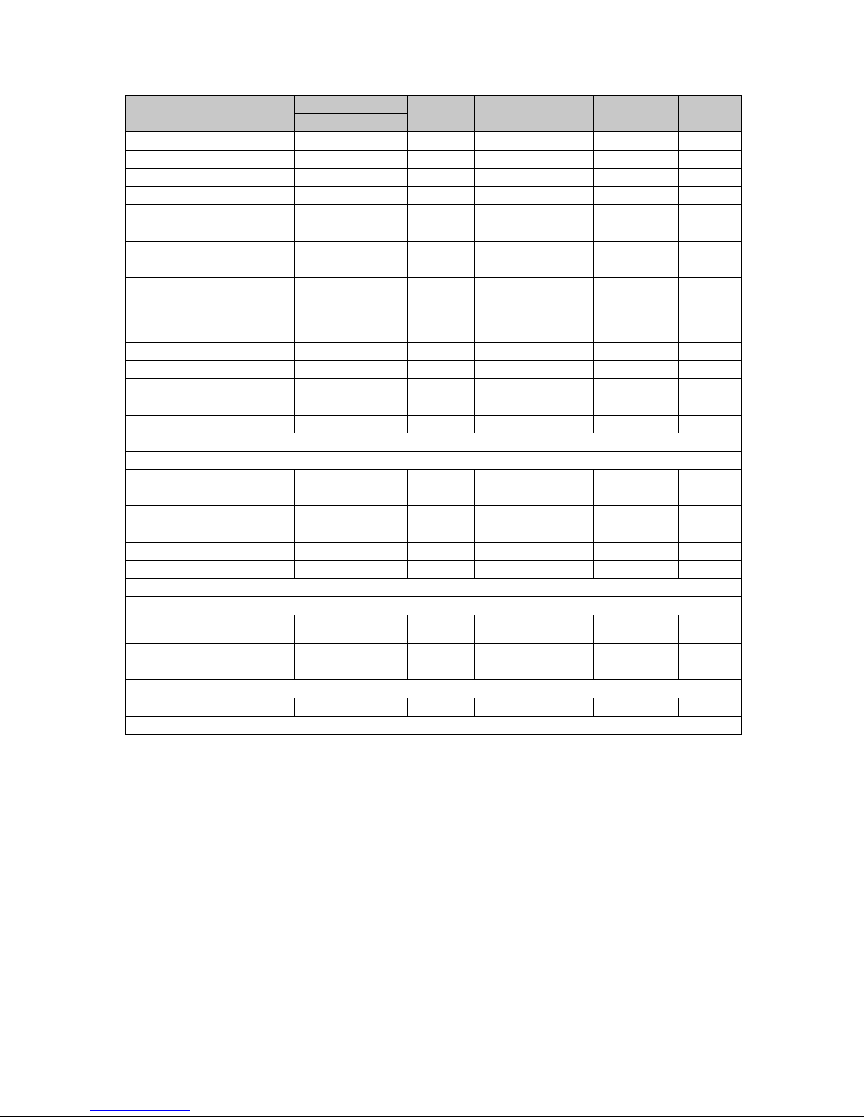
B Overview of the end user operating level
Setting level Values Unit Increment, select Default setting Setting
Min. Max.
Basic display → Right-hand selection button
Room temperature setpoint * Current value ℃
Manual cooling demand*
Basic display → Left-hand selection button
Domestic hot water cylinder target temperature*
Current value ℃
Domestic hot water cylinder actual temperature
Current value ℃
Yield indicator →
Energy yield: Day, Heating Cumulative value kWh
Energy yield: Day, Domestic hot
water
Cumulative value kWh
Energy yield: Day, Cooling Cumulative value kWh
Energy yield: Month, Heating Cumulative value kWh
Working figure: Month, Heating Cumulative value
Energy yield: Total, Heating Cumulative value kWh
Working figure: Total, Heating Cumulative value
Energy yield: Month, Cooling Cumulative value kWh
Working figure: Month, Cooling Cumulative value
Energy yield: Total, Cooling Cumulative value kWh
Working figure: Total, Cooling Cumulative value
Energy yield: Month, Domestic
hot water
Cumulative value kWh
Working figure: Month, Domestic
hot water
Cumulative value
Energy yield: Total, Domestic
hot water
Cumulative value kWh
Working figure: Total, Domestic
hot water
Cumulative value
Total energy consumption Cumulative value kWh
Live Monitor →
Current status message(s) Current value
*If no system control is installed, the menu item is displayed in the product's control panel.
Page 14
Appendix
12 Operating instructions Hydraulic station 0020257319_02
Setting level Values Unit Increment, select Default setting Setting
Min. Max.
Building circuit pressure Current value bar
Heating circuit flow rate Current value l/h
Switch-on delay Outdoor unit Current value min
Switch-on delay Indoor unit Current value min
Flow temp. setpoint Current value ℃
Current flow temp. Current value ℃
Energy integral Current value °min
Cooling capacity Current value kW
Electrical power consumption Current value kW Total power consump-
tion of the heat pump
without any external
components connected (as supplied).
Compressor modulation Current value
Air inlet temperature Current value ℃
Immersion heater power Current value kW
External current anode status Current value
Outdoor temperature Current value ℃
Information →
Contact data Phone number
Serial number Permanent value
Operating hours total Cumulative value h
Hours heating Cumulative value h
DHW operating hours Cumulative value h
Cooling op. hours Cumulative value h
Basic settings →
Language Current language Languages available for
selection
02 English
Display contrast Current value 1 25
15 40
Resets →
No entries available
*If no system control is installed, the menu item is displayed in the product's control panel.
Page 15

Index
0020257319_02 Hydraulic station Operating instructions 13
Index
A
Article number .......................................................................8
B
Battery ...................................................................................9
Brine fluid .............................................................................. 3
Building circuit pressure ........................................................ 7
C
CE marking............................................................................ 6
Comfort protection mode ....................................................... 9
Competent person contact details......................................... 8
Control................................................................................... 8
Cylinder charging .................................................................. 8
D
Decommissioning..................................................................9
Display............................................................................... 4–5
Disposal.................................................................................9
Documents ............................................................................ 4
Domestic hot water generation
Deactivate........................................................................ 8
Domestic hot water temperature
Setting..............................................................................8
E
Environmental energy yield ................................................... 7
F
Fault message .......................................................................9
Filling pressure in the heat pump circuit................................ 8
Filling pressure of the heating installation ............................. 9
Freeze protection .................................................................. 6
Frost ...................................................................................... 3
Frost protection function .................................................... 6, 8
H
Heating flow temperature .................................................... 8
Setting (without a control)................................................8
Heating installation
Draining ...........................................................................8
Heating mode (combination product)
Deactivate........................................................................ 8
Hot gas thermostat ................................................................6
I
Intended use.......................................................................... 2
L
Language ..............................................................................7
M
Maintenance...................................................................... 3, 9
Maintenance message .......................................................... 9
Menu .....................................................................................6
O
Operating concept ................................................................. 6
Operator control elements ................................................. 4–5
P
Pressure in the heat pump circuit .......................................... 8
Product
Disposing......................................................................... 9
Switching on .................................................................... 7
Pump blocking protection ...................................................... 6
R
Recycling............................................................................... 9
Repair.................................................................................... 3
Restricted mode ....................................................................9
S
Safety cut-out ........................................................................6
Serial number .................................................................... 4, 8
Setting the display contrast ................................................... 7
Summer mode .......................................................................8
System pressure ................................................................... 9
T
Troubleshooting.....................................................................9
Page 16

Contents
14 Installation and maintenance instructions Hydraulic station 0020257319_02
Installation and maintenance
instructions
Contents
1 Safety .................................................................. 16
1.1 Action-related warnings ....................................... 16
1.2 Intended use ........................................................ 16
1.3 General safety information .................................. 16
1.4 Regulations (directives, laws, standards)............ 18
1.5 Benchmark........................................................... 18
2 Notes on the documentation ............................ 19
2.1 Observing other applicable documents ............... 19
2.2 Storing documents............................................... 19
2.3 Validity of the instructions.................................... 19
2.4 Further information .............................................. 19
3 Product description........................................... 19
3.1 Heat pump system ............................................... 19
3.2 Safety devices ..................................................... 19
3.3 Cooling mode....................................................... 20
3.4 Functions of the heat pump ................................. 20
3.5 Description of the product.................................... 20
3.6 Product overview ................................................. 20
3.7 Service valve ....................................................... 21
3.8 Information on the data plate ............................... 21
3.9 Connection symbols ............................................ 22
3.10 CE marking .......................................................... 22
3.11 Application limits .................................................. 22
3.12 Buffer cylinder...................................................... 23
4 Set-up.................................................................. 23
4.1 Unpacking the product......................................... 23
4.2 Checking the scope of delivery............................ 23
4.3 Selecting the installation site ............................... 23
4.4 Dimensions.......................................................... 24
4.5 Minimum clearances and installation
clearances ........................................................... 24
4.6 Wall-mounting the product................................... 24
4.7 Removing the front casing................................... 25
4.8 Removing the bottom casing ............................... 25
5 Hydraulics installation ...................................... 26
5.1 Carrying out the installation preparations ............ 26
5.2 Routing refrigerant pipes ..................................... 26
5.3 Connecting the refrigerant pipes ......................... 26
5.4 Checking the refrigerant pipes for tightness ........ 27
5.5 Installing the heating flow and heating return
for the domestic hot water cylinder ...................... 27
5.6 Installing the heating circuit connections ............. 27
5.7 Installing a drain on the expansion relief valve .... 27
6 Electrical installation......................................... 27
6.1 Preparing the electrical installation...................... 27
6.2 Opening the power supply PCB's electronics
box ....................................................................... 28
6.3 Establishing the power supply ............................. 28
6.4 Installing components for the energy supply
company lockout function .................................... 30
6.5 Limiting the power consumption .......................... 30
6.6 Menu functions without the optional system
control .................................................................. 30
6.7 Installing the system control in the electronics
box ....................................................................... 31
6.8 Opening the electronics box ................................ 31
6.9 Cable route .......................................................... 31
6.10 Connecting a limit thermostat for the
underfloor heating................................................ 31
6.11 Carrying out the wiring......................................... 32
6.12 Connecting the circulation pump ......................... 32
6.13 Actuating a circulation pump with an eBUS
controller.............................................................. 32
6.14 Connecting the domestic hot water cylinder ........ 33
6.15 Connecting the external prioritising diverter
valve (optional) .................................................... 33
6.16 Using the additional relays .................................. 33
6.17 Connecting cascades .......................................... 33
6.18 Sealing the power supply PCB ............................ 33
6.19 Checking the electrical installation ...................... 33
7 Start-up ............................................................... 33
7.1 Activating screed drying without the outdoor
unit and system control........................................ 33
7.2 Setting the prioritising diverter valve.................... 34
7.3 Checking and treating the heating water/filling
and supplementary water .................................... 34
7.4 Filling and purging the heating installation .......... 35
7.5 Purging ................................................................ 36
7.6 Starting up the product ........................................ 36
7.7 Running the installation assistants ...................... 36
7.8 Energy balance control ........................................ 36
7.9 Compressor hysteresis ........................................ 37
7.10 Enabling the electric back-up heater ................... 37
7.11 Setting the anti-legionella function....................... 37
7.12 Purging ................................................................ 37
7.13 Calling up the installer level ................................. 37
7.14 Restarting the installation assistants ................... 37
7.15 Calling up statistics .............................................. 37
7.16 Using check programmes .................................... 37
7.17 Carrying out the actuator test .............................. 37
7.18 Starting up the optional system control ............... 37
7.19 Display of the filling pressure in the heat pump
circuit ................................................................... 38
7.20 Preventing low water pressure in the heating
circuit ................................................................... 38
7.21 Checking function and leak-tightness.................. 38
8 Operation............................................................ 38
8.1 Operating concept of the product ........................ 38
Page 17

Contents
0020257319_02 Hydraulic station Installation and maintenance instructions 15
9 Adapting the unit to the heating
installation.......................................................... 38
9.1 Configuring the heating installation ..................... 38
9.2 Remaining feed head of the product ................... 38
9.3 Setting the flow temperature in heating mode
(with no control connected) ................................. 39
9.4 Instructing the end user ....................................... 39
10 Troubleshooting ................................................ 39
10.1 Contacting your service partner........................... 39
10.2 Displaying the Live Monitor (current product
status) .................................................................. 39
10.3 Checking fault codes ........................................... 39
10.4 Querying the fault memory .................................. 39
10.5 Resetting the fault memory.................................. 39
10.6 Using check programmes .................................... 39
10.7 Resetting parameters to factory settings ............. 39
10.8 Safety cut-out....................................................... 39
10.9 Preparing the repair work .................................... 40
11 Inspection and maintenance ............................ 40
11.1 Inspection and maintenance information............. 40
11.2 Procuring spare parts .......................................... 40
11.3 Checking maintenance messages....................... 40
11.4 Observing inspection and maintenance
intervals ............................................................... 41
11.5 Preparing for inspection and maintenance .......... 41
11.6 Checking the admission pressure of the
expansion vessel ................................................. 41
11.7 Checking and correcting the filling pressure of
the heating installation ......................................... 41
11.8 Checking the high-pressure switch-off ................ 41
11.9 Completing inspection and maintenance............. 41
12 Draining .............................................................. 41
12.1 Draining the product's heating circuit................... 41
12.2 Draining the heating installation .......................... 42
13 Decommissioning.............................................. 42
13.1 Temporarily decommissioning the product.......... 42
13.2 Permanently decommissioning the product......... 42
14 Recycling and disposal..................................... 42
14.1 Recycling and disposal ........................................ 42
14.2 Disposing of the product and accessories ........... 42
14.3 Disposing of the refrigerant ................................. 42
Appendix ............................................................................43
A Wiring diagram................................................... 43
B Control PCB ....................................................... 44
C Basic connection diagram for the energy
supply company lockout, shutdown via
connection S21 .................................................. 45
D Basic connection diagram for the energy
supply company lockout, shutdown via
partition .............................................................. 46
E Installer level overview...................................... 47
F Status codes ...................................................... 50
G Maintenance messages .................................... 52
H Comfort protection mode.................................. 53
I Fault codes......................................................... 53
J 5.4 kW back-up heater....................................... 57
K 8.54 kW back-up heater at 230 V ...................... 57
L 8.54 kW back-up heater at 400 V ...................... 58
M Inspection and maintenance work................... 58
N Characteristic values for the temperature
sensor, refrigeration circuit .............................. 58
O Characteristic values for the internal
temperature sensors, hydraulic circuit ........... 59
P Characteristic values for the VR10
internal temperature sensors, cylinder
temperature........................................................ 60
Q Characteristic values for the VRC DCF
outdoor temperature sensor............................. 61
R Technical data.................................................... 61
S Commissioning Checklist ................................. 65
Index ...................................................................................68
Page 18
1 Safety
16 Installation and maintenance instructions Hydraulic station 0020257319_02
1 Safety
1.1 Action-related warnings
Classification of action-related warnings
The action-related warnings are classified in
accordance with the severity of the possible
danger using the following warning signs and
signal words:
Warning symbols and signal words
Danger!
Imminent danger to life or risk of
severe personal injury
Danger!
Risk of death from electric shock
Warning.
Risk of minor personal injury
Caution.
Risk of material or environmental
damage
1.2 Intended use
There is a risk of injury or death to the user or
others, or of damage to the product and other
property in the event of improper use or use
for which it is not intended.
The product is the indoor unit of an air-towater heat pump with split technology.
The product is intended exclusively for domestic use.
The intended use only allows for these
product combinations:
Outdoor unit Indoor unit
VWL ..5/5 AS ... VWL ..8/5 IS ...
VWL ..7/5 IS ...
Intended use includes the following:
– observance of accompanying operating,
installation and maintenance instructions
for the product and any other system components
– installing and setting up the product in ac-
cordance with the product and system approval
– compliance with all inspection and main-
tenance conditions listed in the instructions.
Intended use also covers installation in accordance with the IP code.
Any other use that is not specified in these
instructions, or use beyond that specified in
this document, shall be considered improper
use. Any direct commercial or industrial use
is also deemed to be improper.
Caution.
Improper use of any kind is prohibited.
1.3 General safety information
1.3.1 Risk caused by inadequate
qualifications
The following work must only be carried out
by competent persons who are sufficiently
qualified to do so:
– Set-up
– Dismantling
– Installation
– Start-up
– Inspection and maintenance
– Repair
– Decommissioning
▶ Proceed in accordance with current tech-
nology.
1.3.2 Risk of injury due to the heavy weight
of the product
▶ Make sure that the product is transported
by at least two people.
1.3.3 Risk of death due to lack of safety
devices
The basic diagrams included in this document do not show all safety devices required
for correct installation.
▶
Install the necessary safety devices in the
installation.
▶ Observe the applicable national and inter-
national laws, standards and directives.
1.3.4 Risk of death from electric shock
There is a risk of death from electric shock if
you touch live components.
Before commencing work on the product:
▶ Disconnect the product from the power
supply by switching off all power supplies
at all poles (electrical partition with a con-
Page 19

Safety 1
0020257319_02 Hydraulic station Installation and maintenance instructions 17
tact gap of at least 3 mm, e.g. fuse or circuit breaker).
▶ Secure against being switched back on
again.
▶ Wait for at least 3 minutes until the capa-
citors have discharged.
▶ Check that there is no voltage.
1.3.5 Risk of material damage due to an
unsuitable installation surface
An uneven installation surface may cause
leaks in the product.
▶ Make sure that the product is positioned
flush against the installation surface.
▶ Ensure that the installation surface has
sufficient load-bearing capacity to bear the
operating weight of the product.
1.3.6 Risk of material damage due to
malfunctioning
Not rectifying faults, changing the safety
devices and failing to carry out maintenance
can cause malfunctioning and pose safety
risks during operation.
▶ Ensure that the heating installation is in a
technically perfect condition.
▶ Ensure that no safety or monitoring
devices have been removed, bridged or
disabled.
▶ Immediately eliminate any faults and dam-
age that may affect safety.
1.3.7 Preventing the risk of injury from
freezing as a result of touching
refrigerant
The refrigeration circuit for the indoor unit is
delivered with an operational filling of nitrogen in order to guarantee a check for tightness. The outdoor unit is delivered with an
operational filling of R410A refrigerant. Escaping refrigerant may cause freezing if the
exit point is touched.
▶ If refrigerant escapes, do not touch any
components of the product.
▶ Do not inhale any steam or gases that
escape from the refrigerant circuit as a
result of leaks.
▶ Avoid skin or eye contact with the refriger-
ant.
▶ In the event of skin or eye contact with the
refrigerant, seek medical advice.
1.3.8 Risk of material damage caused by
condensate inside the house
In heating mode, the lines between the heat
pump and the heat source (environment circuit) are cold, which means that condensate
may form on the lines in the house. In cooling
mode, the lines in the building circuit are so
cold that condensate may form if the temperature falls below the dew point. Condensate
may lead to material damage, for example
due to corrosion.
▶ Ensure that you do not damage the heat
insulation on the lines.
1.3.9 Risk of burns, scalds and frostbite
due to hot and cold components
There is a risk of burns and frostbite from
some components, particularly uninsulated
pipelines.
▶ Only carry out work on the components
once they have reached environmental
temperature.
1.3.10 Risk of being scalded by hot drinking
water
There is a risk of scalding at the hot water
draw-off points if the hot water temperatures
are greater than 50 °C. Young children and
elderly persons are particularly at risk, even
at lower temperatures.
▶ Select the temperature so that nobody is at
risk.
1.3.11 Risk of material damage due to
additional elements in the heating
water
Unsuitable frost and corrosion protection
agents may damage seals and other components of the heating circuit and may therefore also lead to leaks in the water outlet.
▶ Only add approved frost and corrosion
protection agents to the heating water.
1.3.12 Risk of material damage caused by
frost
▶ Do not install the product in rooms prone
to frost.
Page 20
1 Safety
18 Installation and maintenance instructions Hydraulic station 0020257319_02
1.3.13 Risk of material damage caused by
using an unsuitable tool
▶ Use the correct tool.
1.3.14 Risk of environmental damage
caused by refrigerant
The product contains a refrigerant with considerable GWP (GWP = Global Warming Potential).
▶ Ensure that the refrigerant does not es-
cape into the atmosphere.
▶ If you are a competent person who is qual-
ified to work with refrigerants, you must
wear appropriate protective equipment
when servicing the product, and access
the refrigerant circuit, if required. Recycle
or dispose of the product in accordance
with the applicable regulations.
1.4 Regulations (directives, laws,
standards)
▶ Observe the national regulations, stand-
ards, directives, ordinances and laws.
1.5 Benchmark
Applicability: Great Britain
Vaillant is a licensed member of the Benchmark Scheme.
Benchmark places responsibilities on both
manufacturers and installers. The purpose is
to ensure that customers are provided with
the correct equipment for their needs, that it
is installed, commissioned and serviced in
accordance with the manufacturer’s instructions by a competent person approved at the
time by the Health and Safety Executive and
that it meets the requirements of the appropriate Building Regulations. The Benchmark
Checklist can be used to demonstrate compliance with Building Regulations and should be
provided to the customer for future reference.
Installers are required to carry out installation,
commissioning and servicing work in accordance with the Benchmark Code of Practice
which is available from the Heating and Hotwater Industry Council who manage and promote the Scheme.
Benchmark is managed and promoted by the
Heating and Hotwater Industry Council.
For more information visit
www.centralheating.co.uk
Page 21
Notes on the documentation 2
0020257319_02 Hydraulic station Installation and maintenance instructions 19
2 Notes on the documentation
2.1 Observing other applicable documents
▶ Always observe all the operating and installation instruc-
tions included with the system components.
2.2 Storing documents
▶ Pass these instructions and all other applicable docu-
ments on to the end user.
2.3 Validity of the instructions
These instructions apply only to:
Product Outdoor unit
VWL 57/5 IS VWL 35/5 AS
VWL 55/5 AS
VWL 77/5 IS VWL 75/5 AS
VWL 127/5 IS VWL 105/5 AS
VWL 125/5 AS
2.4 Further information
▶ Scan the displayed code using your smartphone in order
to view further information about the installation.
◁ You are guided to installation videos.
3 Product description
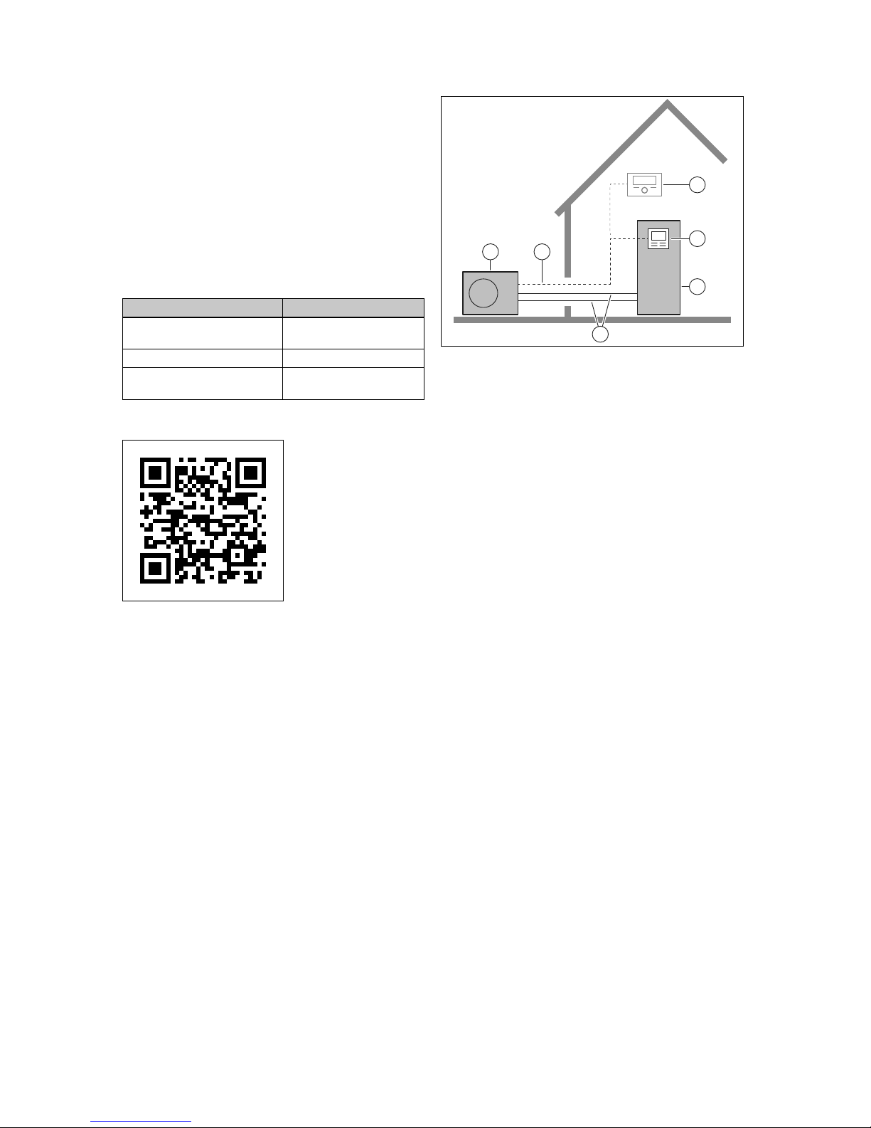
3.1 Heat pump system
Design of a typical heat pump system with split technology:
1 2
4
3
5
6
1 Heat pump, outdoor unit
2 eBUS line
3 System control (op-
tional)
4 Control for the indoor
unit
5 Heat pump, indoor unit
6 Refrigerant circuit
3.2 Safety devices
3.2.1 Frost protection function
The frost protection function for the system is controlled using the product itself or using the optional system control. If
the system control fails, the product guarantees limited frost
protection for the heating circuit.
3.2.2 Low-water pressure protection
This function continuously monitors the pressure of the heating water in order to prevent a possible loss of heating water. If the water pressure falls below the minimum pressure,
an analogue pressure sensor switches off the product and
switches the other modules, where these exist, to standby
mode. The pressure sensor switches the product on again if
the water pressure reaches the operating pressure.
If the pressure in the heating circuit is ≤0.1 MPa (1 bar), a
maintenance message appears below the minimum operating pressure.
– Min. heating circuit pressure: ≥ 0.05 MPa (≥ 0.50 bar)
– Min. heating circuit operating pressure: ≥ 0.07 MPa
(≥ 0.70 bar)
3.2.3 Freeze protection
This function prevents the outdoor unit's evaporator from
freezing when the heat source temperature drops below a
certain value.
The outlet temperature of the heat source is constantly
measured. If the outlet temperature of the heat source falls
below a certain value, the compressor temporarily switches
off and displays a status message. If this fault occurs three
times in a row, it is switched off and a fault message is
displayed.
3.2.4 Pump blocking protection
This function prevents the pumps for heating water from
sticking. The pumps, which were out of operation for
Page 22
3 Product description
20 Installation and maintenance instructions Hydraulic station 0020257319_02
23 hours, are switched on for 10–20 seconds, one after the
other.
3.2.5 Safety cut-out (SCO) in the heating circuit
If the temperature in the heating circuit of the internal electric back-up heater exceeds the maximum temperature, the
safety cut-out shuts down the electric back-up heater as a
securing measure. After it is triggered, the safety cut-out
must be replaced.
– Max. heating circuit temperature: 95 ℃
3.3 Cooling mode
Depending on the country, the product has the heating mode
or heating and cooling mode function.
An optional accessory can be used to subsequently activate
the cooling mode.
3.4 Functions of the heat pump
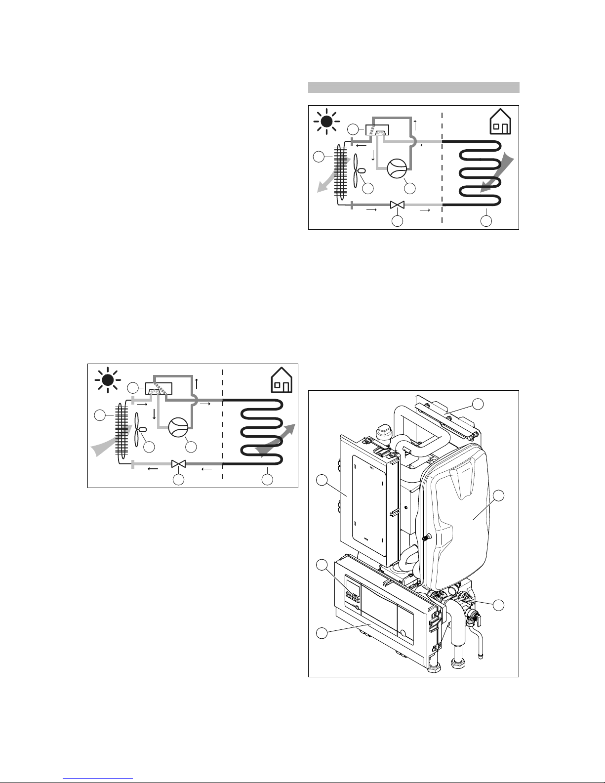
The heat pump has a closed refrigerant circuit in which refrigerant circulates.
In heating mode, cyclic evaporation, compression, liquefaction and expansion take in heat energy from the surroundings and transfer it to the building. In cooling mode, heat
energy is extracted from the building and released into the
environment.
3.4.1 Operating principle, heating mode
65
43
1
2
1 Evaporator (heat ex-
changer)
2 4-port diverter valve
3 Fan
4 Compressor
5 Expansion valve
6 Condenser (heat ex-
changer)
3.4.2 Operating principle, cooling mode
Applicability: Product with cooling mode
65
43
1
2
1 Condenser (heat ex-
changer)
2 4-port diverter valve
3 Fan
4 Compressor
5 Expansion valve
6 Evaporator (heat ex-
changer)
3.5 Description of the product
The product is the indoor unit of an air-to-water heat pump
with split technology.
The indoor unit is connected to the outdoor unit via the refrigerant circuit.
3.6 Product overview
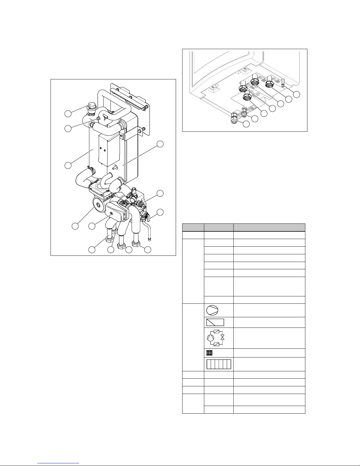
3.6.1 Product design
6
4
5
1
2
3
1 Unit mounting bracket 2 Expansion vessel
Page 23
Product description 3
0020257319_02 Hydraulic station Installation and maintenance instructions 21
3 Hydraulic block
4 Electronics box with
PCB
5 Indoor unit control
6 Electronics box (for
back-up immersion
heater)
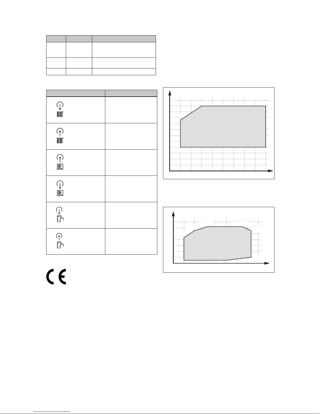
3.6.2 Design of the hydraulic block
10
12
1
2
3
4567
89
11
1 Condenser
2 Pressure sensor (heat-
ing circuit)
3 Expansion relief valve
4 Heating return
5 Heating flow
6 Domestic hot water
cylinder return
7 Domestic hot water
cylinder flow
8 Prioritising diverter
valve (heating circuit/cylinder charging)
9 Heating pump
10 Electric back-up heater
11 Service valve for filling
and creating a vacuum
in the refrigerant circuit
12 Automatic air vent
3.6.3 Underside of the product
1
6
5
4
3
2
7
1 Drain for expansion
relief valve
2 Heating return
3 Heating flow
4 Domestic hot water
cylinder flow
5 Domestic hot water
cylinder return
6 Liquid pipe connection
7 Hot gas pipe connection
3.7 Service valve
At the service valve, you can test the vacuum, carry out
pressure tests, and fill the refrigerant circuit.
3.8 Information on the data plate
The data plate is located on the rear of the electronics box.
Information Meaning
Serial no. Unique unit identification number
Nomenclature
VWL Vaillant, heat pump, air
5, 7, 12 Heating output in kW
7 Heating mode or cooling mode
/5 Unit generation
IS Indoor unit, split technology
230 V Electrical connection:
230 V: 1~/N/PE 230 V
400 V: 3~/N/PE 400 V
IP Protection class
Symbols
Compressor
Control
Refrigerant circuit
Heating circuit
Back-up heater
P max Rated power, maximum
I max Rated current, maximum
I In-rush current
Refrigerant
circuit
MPa (bar) Permissible operating pressure (rel-
ative)
R410A Refrigerant, type
Page 24
3 Product description
22 Installation and maintenance instructions Hydraulic station 0020257319_02
Information Meaning
Refrigerant
circuit
GWP Refrigerant, global warming poten-
tial
Heating
circuit
MPa (bar) Permissible operating pressure
CE marking See section "CE marking"
3.9 Connection symbols
Symbol Connection
Heating circuit, flow
Heating circuit, return
Refrigerant circuit, hot gas
pipe
Refrigerant circuit, liquid pipe
Domestic hot water cylinder,
flow
Domestic hot water cylinder,
return
3.10 CE marking
The CE marking shows that the products comply with the
basic requirements of the applicable directives as stated on
the data plate.
The declaration of conformity can be viewed at the manufacturer's site.
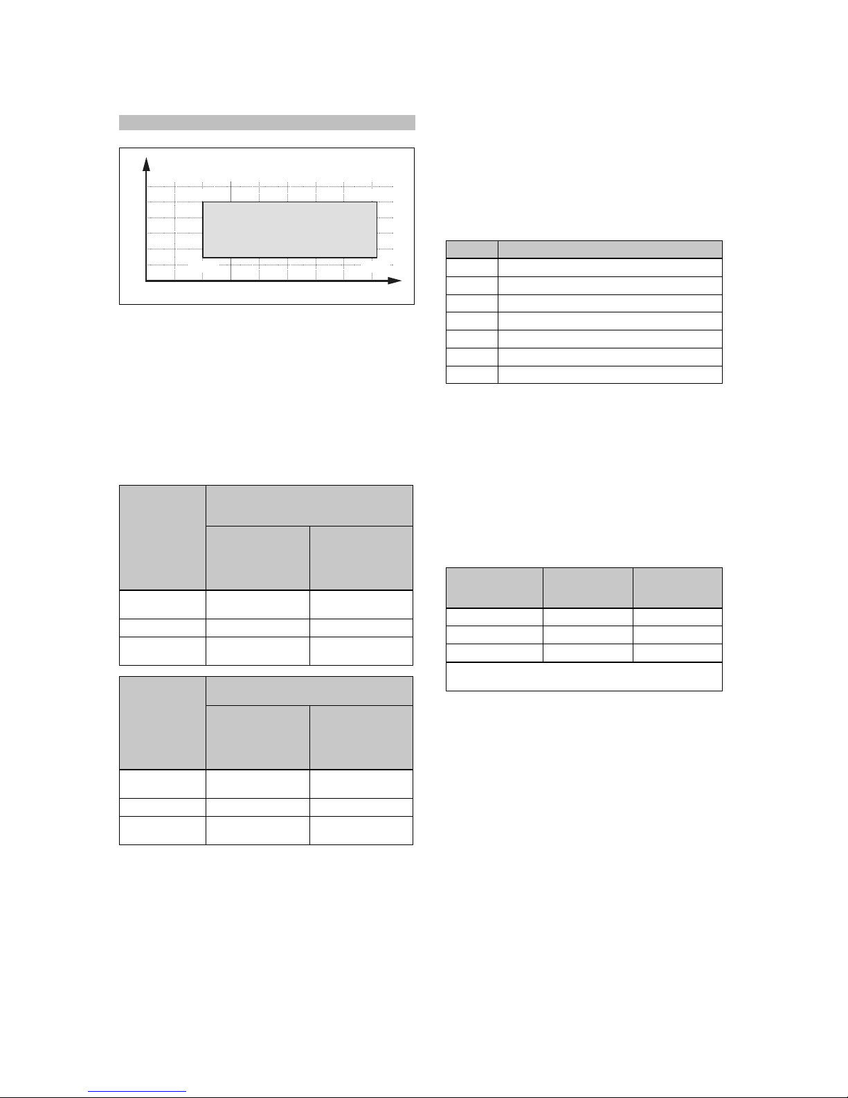
3.11 Application limits
The product works between a minimum and maximum outdoor temperature. These outdoor temperatures define the
operating limits for the heating mode, domestic hot water
mode and cooling mode. See Technical data (→ Page 61).
Operating outside of the operating limits leads to the product
switching off.
3.11.1 Heating mode
[-20;20]
[-20;43]
[20;55]
[-10;55]
[20;20]
A
B
30
35
40
45
50
55
60
25
20
15
10
5
0
-20 -15 -10 -5 0 5 10 15 20
A Outdoor temperature B Heating water temperat-
ure
3.11.2 DHW mode
[-20;43]
[35;62]
[-10;55]
[-20;5]
[2;62]
[20;5]
[43;55]
[43;10]
A
B
60
70
50
40
30
20
10
0
-20 -10 0 10 20 30 40 50
A Outdoor temperature B Domestic hot water
temperature
Page 25
Set-up 4
0020257319_02 Hydraulic station Installation and maintenance instructions 23
3.11.3 Cooling mode
Applicability: Product with cooling mode
[15;7]
[15;25]
[46;7]
[46;25]
A
B
30
25
20
15
10
5
0 1015202530354045
A Outdoor temperature B Heating water temperat-
ure
3.12 Buffer cylinder
Heating installations, which mainly consist of fan coils or radiators, usually contain a low volume of water. We recommend installing a buffer cylinder. In the case of two or more
heating circuits in the system, a buffer cylinder or a low loss
header should also be used as decoupling.
For the outdoor unit, it is important for the evaporator's deicing process that sufficient thermal energy can be provided.
Heat pump in
the split system
Minimum installation volume
For heating circuit with underfloor heating and fan coils
When the heating
system is active
in winter and the
back-up heater is
deactivated
When the heating
system is active
in winter and the
back-up heater is
active
3 kW and 5 kW
output
40 l 15 l
7 kW output 55 l 20 l
10 kW and
12 kW output
150 l 45 l
Heat pump in
the split system
Minimum installation volume
For heating circuit with radiators
When the heating
system is active
in winter and the
back-up heater is
deactivated
When the heating
system is active
in winter and the
back-up heater is
active
3 kW and 5 kW
output
100 l 20 l
7 kW output 130 l 30 l
10 kW and
12 kW output
250 l 50 l
4 Set-up
4.1 Unpacking the product
1. Remove the product from the packaging.
2. Remove the documentation.
3. Remove the protective film from all parts of the product.
4.2 Checking the scope of delivery
▶ Check that the scope of delivery is complete and intact.
Number Designation
1
Hydraulic station
1
Enclosed documentation
1
Bag with installation material
1 Selection lever for prioritising diverter valve
1 Filling device
1 5-pole 400 V connection cable
1 Adhesive strips for noise reduction
4.3 Selecting the installation site
▶ The installation site must be below 2000 metres above
sea level.
▶ Select a dry room that is frost-proof throughout and in
which the maximum installation height is not exceeded
and the environmental temperature is neither above nor
below the permitted range.
– Permissible environmental temperature: 7 … 25 ℃
– Permissible relative air humidity: 40 … 75 %
▶ Ensure that the installation room has the required min-
imum volume.
Heat pump R410A refri-
gerant filling
volume
Minimum installation room
volume
VWL 57/5 IS 1.5 kg 3.41 m³
VWL 77/5 IS 2.4 kg 5.45 m³
VWL 127/5 IS 3.6 kg 8.18 m³
Minimum installation room = refrigerant filling volume
(kg)/practical limit value (kg/m³) (for R410A = 0.44 kg/m³)
▶ Ensure that the required minimum clearances can be
maintained.
▶ Observe the permissible height difference between out-
door unit and indoor unit. See the technical data in the
appendix.
▶ When selecting the installation site, you must take into
consideration that when the heat pump is in operation, it
will transfer vibrations to the walls.
▶ Ensure that the wall is even and offers sufficient load-
bearing capacity to bear the weight of the product.
▶ Ensure that pipes can be easily routed in an appropriate
way (domestic hot water side, heating side and refrigerant side).
▶ Do not install the product above another unit that may
damage it (e.g. above a cooker that produces water vapour and grease) or in a room with a high level of exposure to dust or in a corrosive environment.
▶ Do not install the product below a unit from which liquids
may flow.
Page 26
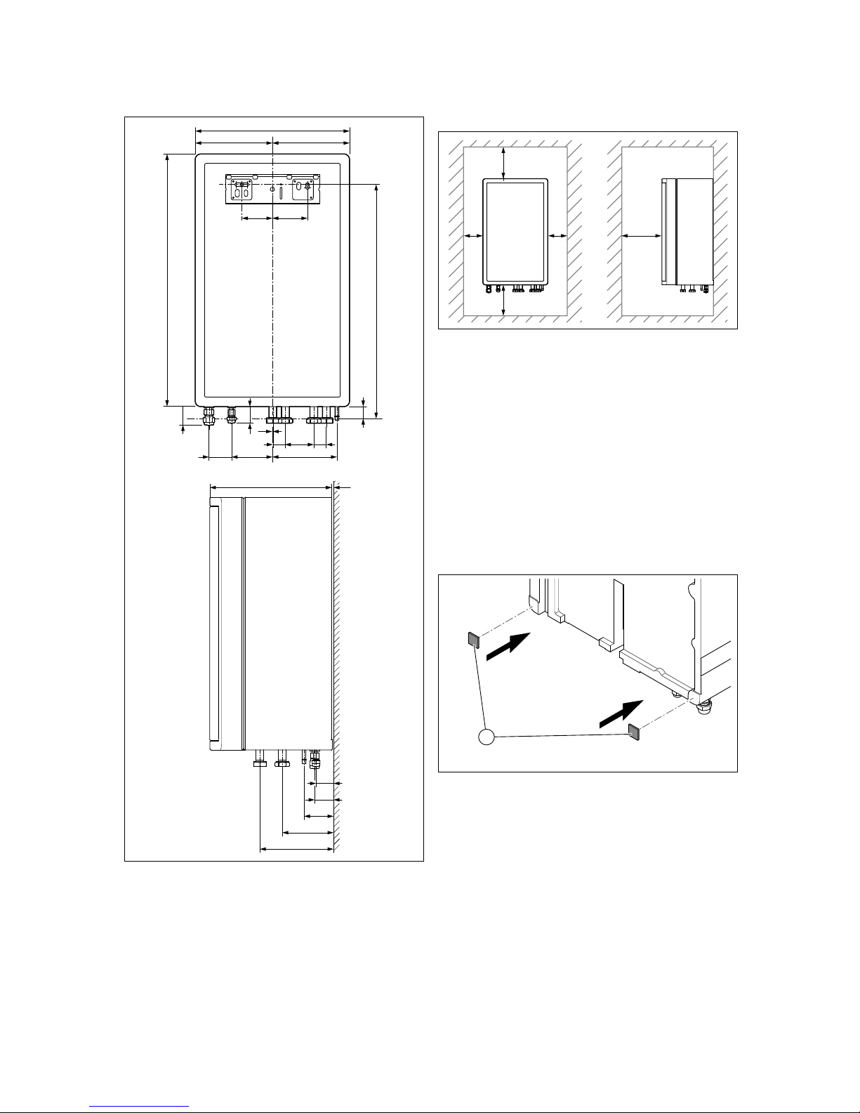
4 Set-up
24 Installation and maintenance instructions Hydraulic station 0020257319_02
4.4 Dimensions
440
220
220
184116 ,264,5
720
667
368136
35
39
1
27
87 101
350 2
47
51
81
143
207
4.5 Minimum clearances and installation
clearances
BB
AC
D
A Min. 200 mm
B Min. 200 mm
C 1000 mm
D > 600 mm
▶ Provide sufficient clearance on both sides of the product
in order to facilitate access for maintenance and repair
work.
▶ When using the accessories, observe the minimum clear-
ances/installation clearances.
▶ Ensure that no highly flammable parts come into contact
with the components as these may reach temperatures of
over 80°C.
▶
Ensure that there is a minimum clearance between the
highly flammable parts and the hot components.
– Minimum clearance: 200 mm
4.6 Wall-mounting the product
1
1. Cut the enclosed adhesive strips for noise reduction
into two equally sized pieces (3 cm x 3 cm).
2. Affix the adhesive strips to the product as shown in the
figure.
Page 27
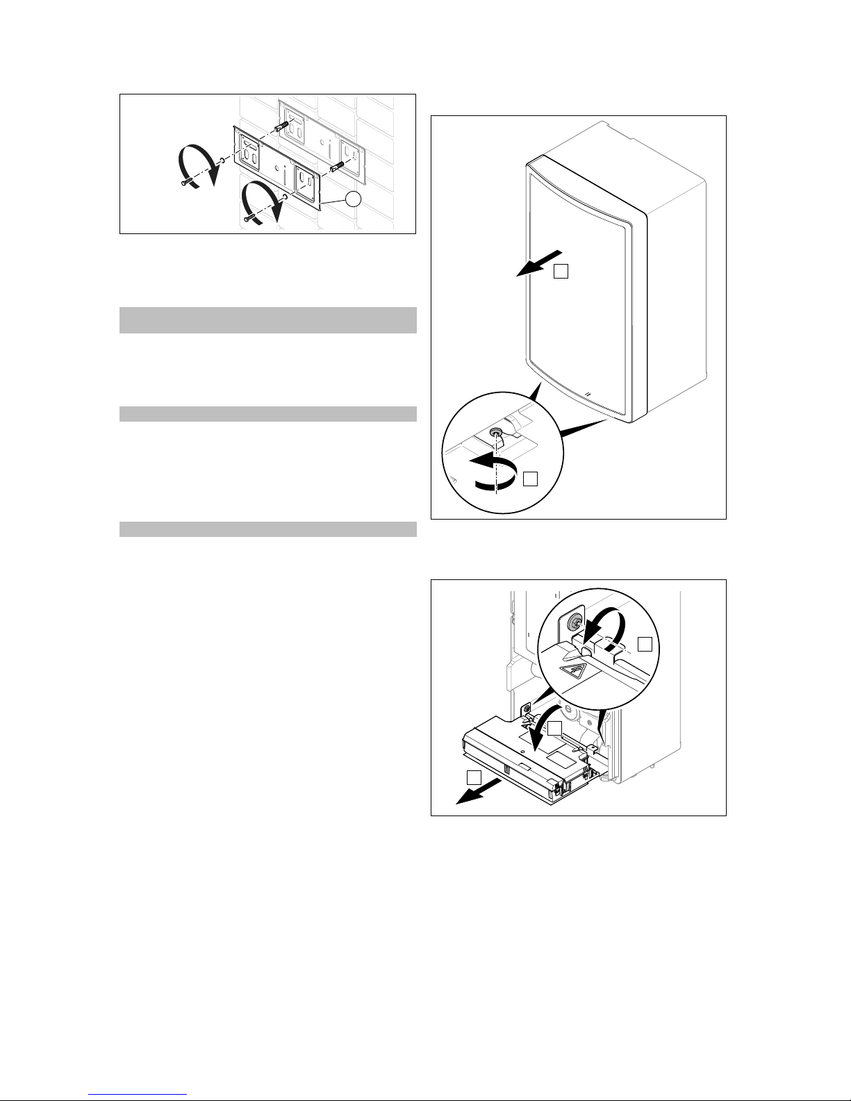
Set-up 4
0020257319_02 Hydraulic station Installation and maintenance instructions 25
1
3. Check whether the wall has sufficient load-bearing capacity to bear the operating weight of the product.
4. Check if the supplied fixing material may be used for
the wall.
Condition: The load-bearing capacity of the wall is sufficient, The fixing
material is permitted for the wall
▶ Secure the unit mounting bracket to the wall as
described in the figure.
▶ Suspend the product on the unit mounting bracket from
above using the hanging bracket.
Condition: The load-bearing capacity of the wall is not sufficient
▶ Ensure that wall-mounting apparatus on-site has a suf-
ficient load-bearing capacity. Use individual stands or
primary walling, for example.
▶ Do not wall-mount the product if you cannot provide
wall-mounting apparatus with a sufficient load-bearing
capacity.
Condition: The fixing material is not permitted for the wall
▶ Wall-mount the product as described in the illustration
using the permitted fixing material provided on-site.
4.7 Removing the front casing
A
B
▶ Reinstall the components in the reverse order.
4.8 Removing the bottom casing
B
C
A
1. Hinge the electronics box forwards.
2. Open the electronics box and remove the top cover.
3. Remove the plug from the PCB.
4. Remove both screws as shown in the figure.
5. Pull out the electronics box towards the front.
6. Pull out the bottom casing towards the front.
7. Reinstall the components in the reverse order.
Page 28
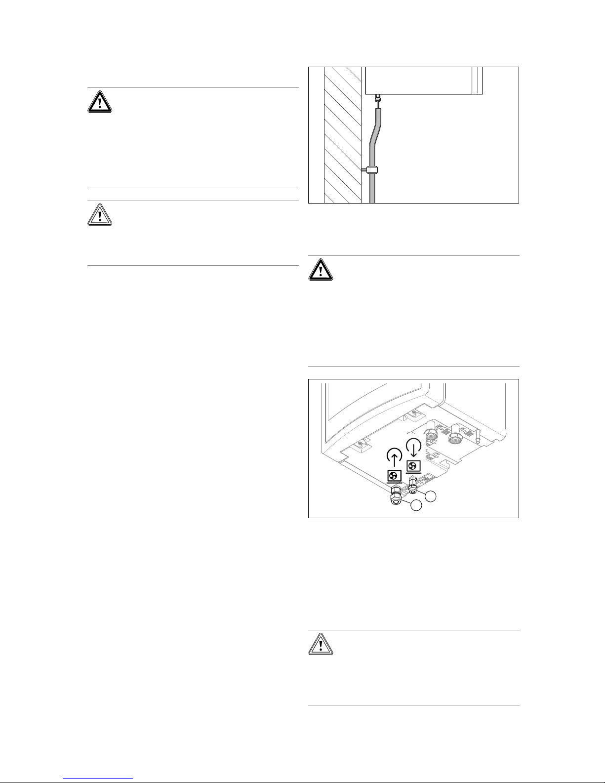
5 Hydraulics installation
26 Installation and maintenance instructions Hydraulic station 0020257319_02
5 Hydraulics installation
Danger!
Risk of scalding and/or risk of material
damage due to incorrect installation leading to escaping water.
Stresses in connection pipes can cause
leaks.
▶ Install the connection pipes such that they
are free from mechanical stress.
Caution.
Risk of material damage due to heat trans-
fer during soldering.
▶ Only solder connectors if the connectors
are not yet screwed to the service valves.
5.1 Carrying out the installation preparations
▶ Install the following components, preferably from the
manufacturer's accessories:
– An expansion relief valve, a stopcock and a mano-
meter on the heating return
– A domestic hot water safety group and a stopcock on
the cold water supply
– A stopcock on the heating flow
▶ Check whether the volume of the installed expansion
vessel is sufficient for the heating system. If the volume
of the installed expansion vessel is insufficient, install an
additional expansion vessel, connected as close to the
product as possible, in the heating return.
▶ Flush the heating installation through thoroughly before
connecting the product in order to remove any residue
which could be deposited in the product and lead to damage.
▶ Check whether, when you open the catches on the refri-
gerant pipes, you can hear a hissing sound (caused by
a factory-side excess pressure of nitrogen). If you do not
find any excess pressure, check all of the screwed connections and pipes for leaks.
▶ For heating installations with solenoid valves or thermo-
statically controlled valves, install a bypass with bypass
valve in order to guarantee a volume flow of at least 40%.
5.2 Routing refrigerant pipes
1. Observe the information on handling refrigerant pipes in
the installation instructions for the outdoor unit.
2. Route the refrigerant pipes from the wall duct to the
product.
3. Bend the pipes only once into their final position. Use a
bending spring or another suitable bending tool to avoid
kinks.
4. Secure the pipes to the wall using insulated wall brackets (cold insulation brackets).
5.3 Connecting the refrigerant pipes
Danger!
Risk of injury and risk of environmental
damage due to escaping refrigerant.
Touching any escaping refrigerant may
cause injury. Escaping refrigerant leads
to environmental damage if it reaches the
atmosphere.
▶ Only carry out work on the refrigerant cir-
cuit if you have been trained to do so.
1
2
1. Remove the flare nuts and the catches from the connections for the refrigerant pipes on the product.
◁ An audible hissing sound (escaping nitrogen) shows
that the refrigerant circuit in the product is leak-tight.
2. Apply a drop of flare oil to the outsides of the pipe ends
in order to prevent the flare edge from breaking away
when tightening screwed connections.
3. Connect the hot gas pipe (2). Use the product's flare
nuts.
Caution.
Risk of damage to the refrigerant pipes
caused by excessive tightening torque
▶ Note that the following torques only refer
to flanged connections. The torques for
SAE connections are lower.
Page 29
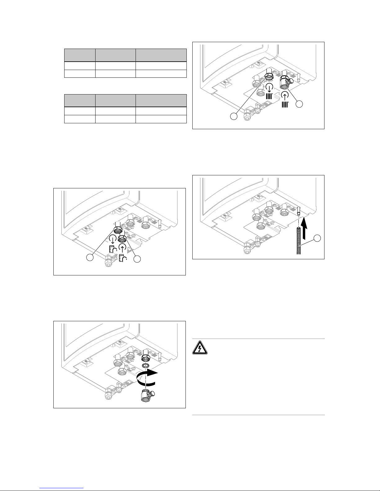
Electrical installation 6
0020257319_02 Hydraulic station Installation and maintenance instructions 27
4. Tighten the flare nut.
Heating
output
Pipe diameter Tightening torque
3 to 5 kW 1/2 " 50 … 60 Nm
7 to 12 kW 5/8 " 65 … 75 Nm
5. Connect the liquid pipe (1). Use the product's flare nuts.
6. Tighten the flare nut.
Heating
output
Pipe diameter Tightening torque
3 to 5 kW 1/4 " 15 … 20 Nm
7 to 12 kW 3/8 " 35 … 45 Nm
5.4 Checking the refrigerant pipes for tightness
1. Check the refrigerant pipes for tightness (see the installation instructions for the outdoor unit).
2. Ensure that the heat insulation of the refrigerant pipes is
still sufficient after installation.
5.5 Installing the heating flow and heating return
for the domestic hot water cylinder
1
2
▶ Install the heating return (1) and the heating flow (2) for
the domestic hot water cylinder in accordance with the
relevant standards.
Connection symbols (→ Page 22)
5.6 Installing the heating circuit connections
1. Install the filling device on the product's heating return
using the seal provided.
1
2
2. Install the return (1) and the flow (2) for the heating circuit in accordance with the relevant standards.
Connection symbols (→ Page 22)
5.7 Installing a drain on the expansion relief
valve
1
1. Install a drain hose (1) on the expansion relief valve.
2. Install the expansion relief valve hose in a frost-free
environment and ensure that its routing ends in an open
drain where it is then visible.
3. Ensure that escaping water does not endanger any
people or electronic components.
6 Electrical installation
6.1 Preparing the electrical installation
Danger!
Risk of death from electric shock as a res-
ult of an improper electrical connection!
An improper electrical connection may negatively affect the operational safety of the
product and result in material damage or personal injury.
▶ Only carry out the electrical installation if
you are a trained competent person and
are qualified for this work.
Page 30
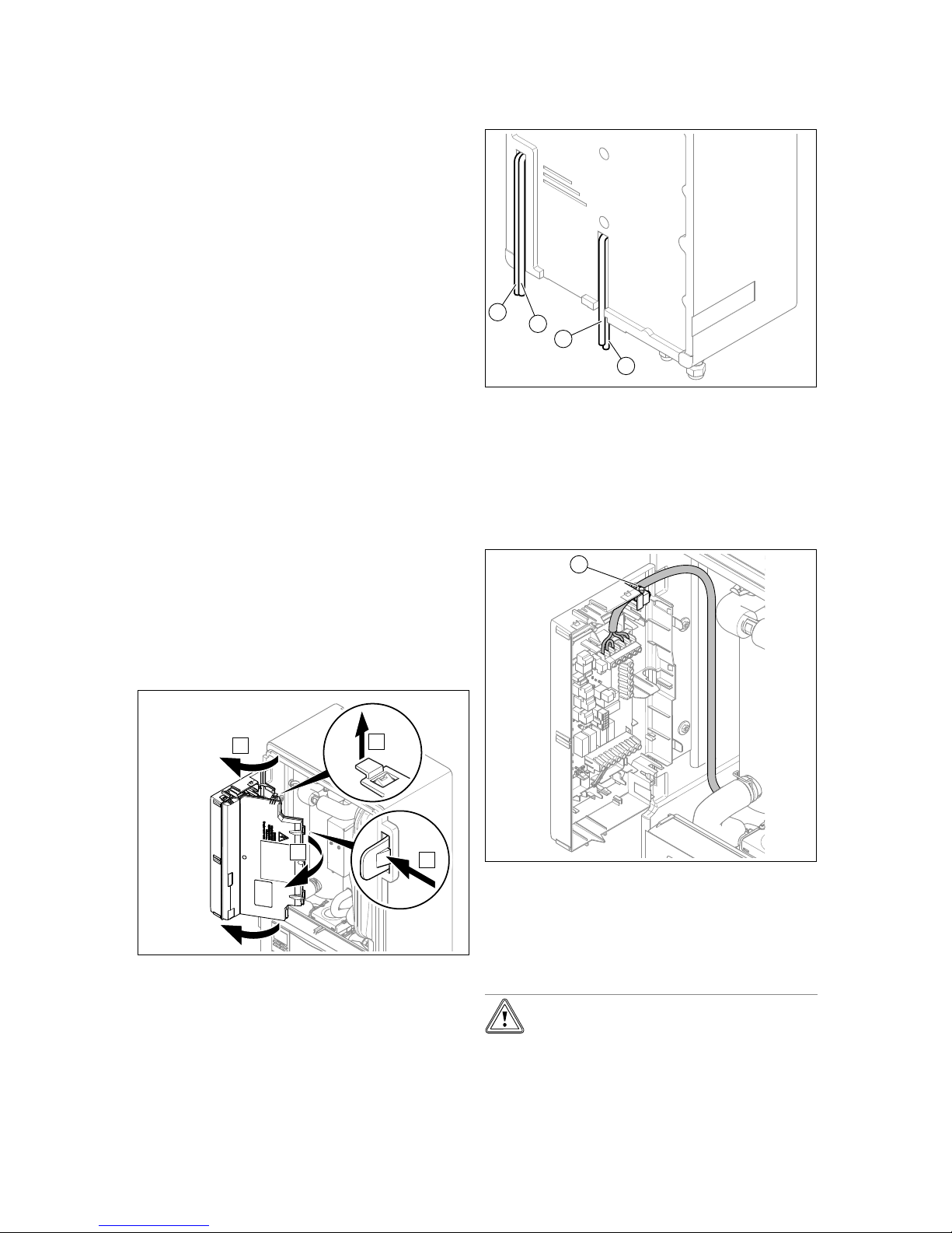
6 Electrical installation
28 Installation and maintenance instructions Hydraulic station 0020257319_02
1. Observe the technical connection conditions for connecting to the energy supply company's low-voltage
network.
2. Use the data plate to determine whether the product
requires a 1~/230V or a 3~/400V electrical connection.
3. The product is preconfigured for the unblocked 1~/230V
connection.
4. Determine whether the power supply for the product
should be set up with a single-tariff meter or a dual-tariff
meter.
5. Ensure that the nominal voltage of the single-phase
network is 230 V (+10%/-15%) and the nominal voltage
of the 3-phase network is 400 V (+10–15%).
6. Connect the product using a fixed connection and a
partition with a contact gap of at least 3 mm (e.g. fuses
or power switches).
7. Use the data plate to determine the product's rated
current. Derive the suitable cable cross-sections
for the electrical wires from this. The requirements
for the cables can be found in from (→ Page 28) to
(→ Page 29).
8. In each case, take into consideration the (on-site) installation conditions.
9. Ensure that the nominal voltage of the power grid corresponds to that of the product's main power supply
cabling.
10. Make sure that access to the power supply is always
available and is not covered or blocked.
11. If the local power supply network operator requires that
the heat pump is controlled using a blocking signal,
install a corresponding contact switch as prescribed
by the power supply network operator.
6.2 Opening the power supply PCB's electronics
box
1. Remove the front casing. (→ Page 25)
B
C
A
D
2. Hinge the electronics box forwards.
3. Detach the four clips, on the left and the right, from the
brackets.
6.3 Establishing the power supply
2
3
4
1
1. Remove the front casing. (→ Page 25)
2. Open the power supply PCB's electronics box.
(→ Page 28)
3. Guide the power supply cable (3) and other power supply cables (230 V) (4) through the central unit opening
and into the product.
4. Guide the eBUS cable (1) and other low-voltage connection cables (24 V) (2) through the left-hand unit
opening and into the product.
1
5. Guide the power supply cables through the strain relief
(1) to the terminals on the power supply PCB.
6. Connect the power supply cable to the corresponding
terminals.
7. Secure the power supply cable in the strain reliefs.
6.3.1 1~/230V single power supply
Caution.
Risk of material damage due to high con-
nected voltage.
With excessive mains voltages, electronic
components may be damaged.
Page 31
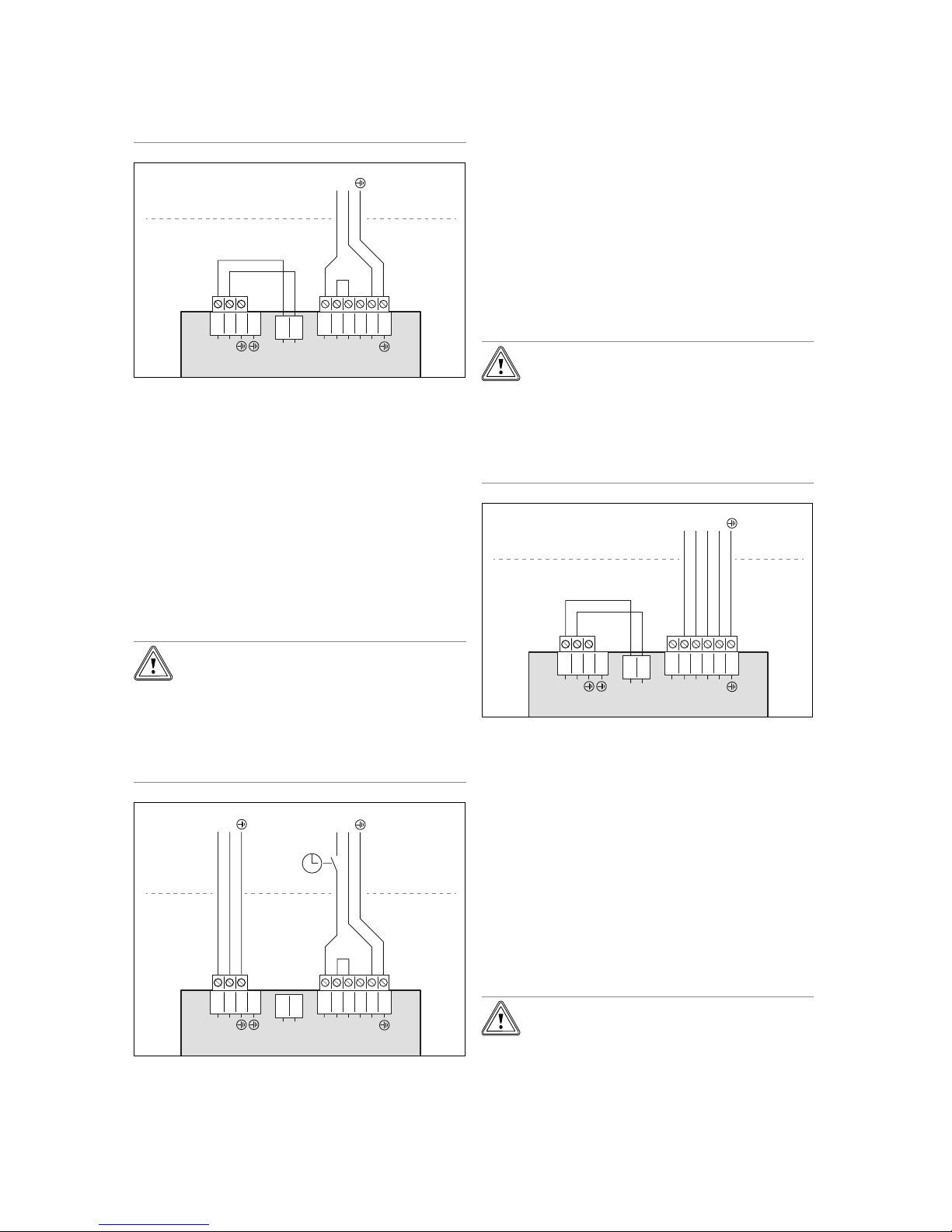
Electrical installation 6
0020257319_02 Hydraulic station Installation and maintenance instructions 29
▶ Ensure that the mains voltage is in the
permissible range.
12345
6
L1
L1
L2
L3
N
X300X310X311
2
1
L1
N
3
4
1
2
N
L
N
L
1. Install a separate type B residual-current circuit breaker
for the product.
2. Note the specifications on the sticker on the electronics
box.
3. Use a 3-pole power supply cable with a conductor
cross-section of 4 mm2and a temperature resistance of
90 °C.
4. Remove the cable jacket until there is only 30 mm left.
5. Connect the power supply cable to L1, N, PE, as
shown.
6. Use the strain relief clamp to secure the cable in place.
7. Observe the instructions on connecting a dual-tariff
supply; see (→ Page 30).
6.3.2 1~/230V dual power supply
Caution.
Risk of material damage due to high con-
nected voltage.
With excessive mains voltages, electronic
components may be damaged.
▶ Ensure that the mains voltage is in the
permissible range.
12345
6
L1
L1
L2
L3
N
X300X310X311
2
1
L1
N
341
2
N
L
N
L
N
L
1. Install a separate type B residual-current circuit breaker
for the product.
2. Note the specifications on the sticker on the electronics
box.
3. Use a 3-pole power supply cable (low tariff) with a conductor cross-section of 4 mm2and a temperature resist-
ance of 90 °C. Use a 3-pole power supply cable (high
tariff) with a conductor cross-section of 0.75 mm2and a
temperature resistance of 90 °C.
4. Remove the cable jacket until there is only 30 mm left.
5. Connect the power supply cable, as shown.
6. Use the strain relief clamp to secure the cable in place.
7. Observe the instructions on connecting a dual-tariff
supply; see (→ Page 30).
6.3.3 3~/400V single power supply
Caution.
Risk of material damage due to high con-
nected voltage.
With excessive mains voltages, electronic
components may be damaged.
▶ Ensure that the mains voltage is in the
permissible range.
12345
6
L1
L1
L2
L3
N
L1L2L3
N
X300X310X311
2
1
L1
N
3
4
1
2
N
L
L
1. Install a separate type B residual-current circuit breaker
for the product.
2. Note the specifications on the sticker on the electronics
box.
3. Use a 5-pole power supply cable with a conductor
cross-section of 2.5 mm2and a temperature resistance
of 90 °C.
4. Remove the cable jacket until there is only 70 mm left.
5. Remove the jumper from between connections L1 and
L2.
6. Connect the power supply cable to L1, L2, L3, N, PE,
as shown.
7. Observe the instructions on connecting a dual-tariff
supply; see (→ Page 30).
6.3.4 3~/400V dual power supply
Caution.
Risk of material damage due to high con-
nected voltage.
With excessive mains voltages, electronic
components may be damaged.
Page 32
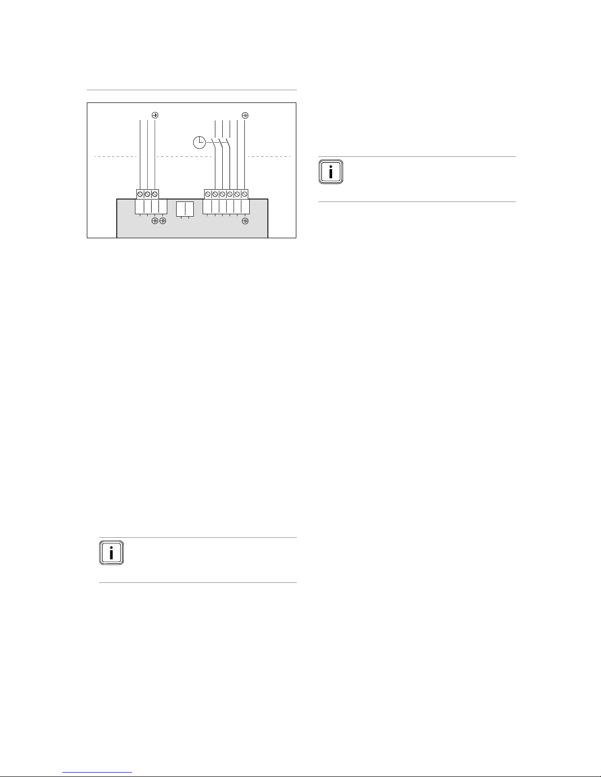
6 Electrical installation
30 Installation and maintenance instructions Hydraulic station 0020257319_02
▶ Ensure that the mains voltage is in the
permissible range.
12345
6
L1
L1
L2
L3
N
X300X310X311
2
1
L1
N
3
4
1
2
N
L
L
N
L
L1L2L3
N
1. Install a separate type B residual-current circuit breaker
for the product.
2. Note the specifications on the sticker on the electronics
box.
3. Use a 5-pole power supply cable (low tariff) with a conductor cross-section of 2.5 mm2and a temperature res-
istance of 90 °C. Use a 3-pole power supply cable (high
tariff) with a conductor cross-section of 0.75 mm2and a
temperature resistance of 90 °C.
4. Remove the cable jacket until there is only 70 mm left
for the 5-pole cable, and only 30 mm left for the 3-pole
cable.
5. Remove the jumper from between connections L1 and
L2.
6. Connect the power supply cable, as shown.
7. Observe the instructions on connecting a dual-tariff
supply; see (→ Page 30).
6.4 Installing components for the energy supply
company lockout function
The heat generation of the heat pump can be switched off intermittently. It is switched off by the energy supply company
and usually with a ripple control receiver.
Option 1: Actuating connection S21
▶ Connect a 2-pole control cable to the relay contact (po-
tential-free) for the ripple control receiver and to the connection S21, see appendix.
Note
In the event of control via connection S21, the
energy supply does not have to be disconnected on-site.
▶ In the system control, set whether the back-up heater,
the compressor or both should be blocked.
▶ Set the parametrisation for connection S21 in the system
control.
Option 2: Disconnect the power supply with contactor
▶ Upstream of the indoor unit, install a contactor into the
power supply for the low tariff.
▶ Install a 2-pole control cable. Connect the control output
for the ripple control receiver to the control input for the
contactor.
▶ Undo the lines to plug X311, which were installed at the
factory, and remove these along with plug X310.
▶ Connect an unblocked power supply to X311.
▶ Connect the power supply that is switched by the con-
tactor to X300, see appendix.
Note
When the energy supply (for the compressor
or back-up heater) is switched off via the tariff
contactor, S21 is not connected.
6.5 Limiting the power consumption
The electrical power for the back-up heater on the product
and the compressor for the outdoor unit can be limited. You
can set the maximum output in the product's display.
6.6 Menu functions without the optional system
control
If no system control is installed and this has been confirmed
in the installation assistant, the following additional functions
are displayed in the indoor unit's control panel:
– End user level
– Room temperature setpoint
– Screed drying activ.
– Target cylinder temp.
– Domestic hot water cylinder temp.
– Manual cooling activation
– Installer level
– Heat curve
– Summer sw.-off temp.
– Heating biv. point
– DHW bivalence point
– Heating alt. point
– Max. flow temperature
– Min. flow temperature
– Heating mode activ.
– DHW activation
– Cyl. charg. hysteresis
– Limp home mode Immersion heater: Heating/DHW
– Cooling target flow
– Screed drying day
If the system control has been retroactively removed or a
defect is present, you must restart the installation assistant
and confirm the function without a system control in order
to obtain the additional functions in the indoor unit's control
panel.
Page 33
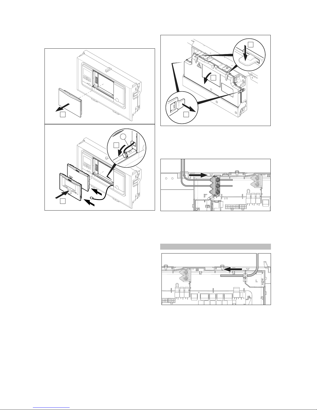
Electrical installation 6
0020257319_02 Hydraulic station Installation and maintenance instructions 31
6.7 Installing the system control in the
electronics box
A
C
B
1
1. Remove the cover from the electronics box.
2. Connect the DIF cable – laid out ready – to the system
control or to the radio receiver.
3. If you are using a radio receiver, use the mobile base
station.
4. If you are using the wired system control, use the sys-
tem control.
5. Consult the instructions for the system control for in-
formation on coupling the mobile base station and the
system control.
6.8 Opening the electronics box
1. Remove the front casing. (→ Page 25)
B
A
C
2. Hinge the electronics box
(1) forwards.
3. Detach the four clips (3), on the left and the right, from
the brackets.
6.9 Cable route
24V / eBUS
▶ Route the 24 V cable and the eBUS cable through the
left-hand strain reliefs on the electronics box.
6.10 Connecting a limit thermostat for the
underfloor heating
Condition: If you are connecting a limit thermostat for underfloor heating:
230V
▶ Route the 230 V cable through the right-hand strain re-
liefs on the electronics box.
▶ Pull out the S20 plug for the bypass line at terminal
X100 on the control PCB.
▶ Connect the limit thermostat to plug S20.
Page 34
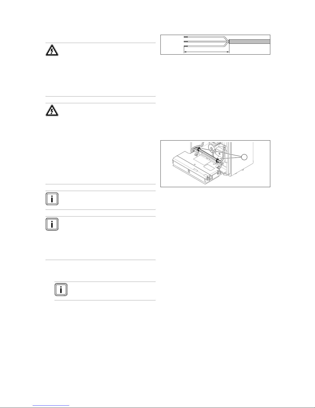
6 Electrical installation
32 Installation and maintenance instructions Hydraulic station 0020257319_02
6.11 Carrying out the wiring
Danger!
Risk of death from electric shock!
Continuous voltage is present at power supply terminals L1, L2, L3 and N:
▶ Switch off the power supply.
▶ Check that there is no voltage.
▶ Secure the power supply against being
switched back on.
Danger!
Risk of injury and material damage
caused by incorrect installation.
Mains voltage at incorrect terminals and plug
terminals may destroy the electronics.
▶ Ensure that the mains voltage is correctly
disconnected from the safety extra-low
voltage.
▶ Do not connect any mains voltage to ter-
minals BUS, S20, S21, X41.
▶ Only connect the power supply cable to
the terminals that are marked for the purpose.
Note
There is a safety extra-low voltage (SELV) at connections S20 and S21.
Note
If the energy supply company lockout function is
used, connect a potential-free normally open contact with a breaking capacity of 24 V/0.1 A to connection S21. You must configure how the connection works in the system control. (For example, if
the contact is closed, the electric back-up heater
is blocked.)
1. Route the sensor and bus lines into the product through
the rear of the product (→ Page 28).
Note
The cables must fit through the corresponding grommet.
2. At lengths of 10 m or more, mains voltage connection
cables must be laid separately from sensor or bus lines.
Minimum clearance for the extra low-voltage wire and
power supply cable at a line length of > 10 m: 25 cm. If
this is not possible, use shielded lines. Lay the shielding
on one side of the sheet for the product's electronics
box.
3. Shorten the connection cables according to requirements.
30 mm
≤
4. To prevent short circuits if a strand accidentally comes
loose, only strip the outer sheathing of flexible lines to a
maximum of 30 mm.
5. Ensure the inner conductor insulation is not damaged
when stripping the outer sheathing.
6. Only strip inner conductors just enough to establish
good, sound connections.
7. To avoid short circuits resulting from loose individual
wires, fit conductor end sleeves on the stripped ends of
the conductors.
8. Screw the respective plug to the connection cable.
9. Check whether all conductors are inserted mechanically
securely in the terminals of the plug. Remedy this if
necessary.
10. Plug the plug into the associated PCB slot.
1
11. Use the strain reliefs (1).
6.12 Connecting the circulation pump
1. Carry out the wiring. (→ Page 32)
2. Route the 230 V connection cable for the circulation
pump from the right and into the control PCB's electronics box.
3. Connect the 230 V connection cable to the plug from
slot X11 on the control PCB and plug it into the slot.
4. Connect the connection cable for the external button
using terminals 1 (0) and 6 (functional drawing) on the
X41 edge connector, which is supplied with the control.
5. Plug the edge connector into slot X41 on the control
PCB.
6.13 Actuating a circulation pump with an eBUS
controller
1. Ensure that the circulation pump is correctly parametrised in the system control.
2. Select a hot water programme (preparation).
3. Parametrise a circulation programme in the system
control.
◁ The pump runs during the time period specified in
the programme.
Page 35
Start-up 7
0020257319_02 Hydraulic station Installation and maintenance instructions 33
6.14 Connecting the domestic hot water cylinder
1. Connect the temperature sensor (VR10) for the domestic hot water cylinder to the corresponding connection for cable harness X22 on the control PCB.
2. If an external current anode is installed in the domestic
hot water cylinder, connect it to X313 or X314 on the
power supply PCB.
◁ The connection plug is included in the bag of small
parts.
6.15 Connecting the external prioritising diverter
valve (optional)
▶ Connect the external prioritising diverter valve to X14 on
the control PCB.
– The connection to a permanently live phase "L" with
230 V and to a switched phase "S" is available.
Phase "S" is actuated by an internal relay and
releases 230 V.
6.16 Using the additional relays
▶ If required, consult the installation diagram handbook
that is contained in the scope of delivery for the system
control and the handbook for the optional module.
6.17 Connecting cascades
▶ If you want to use cascades (max. seven units), you must
connect the eBUS line to contact X100 via the VR32b
bus coupler (accessory).
6.18 Sealing the power supply PCB
1. Tighten all of the screws on the strain relief clamps.
2. Close the cover for the electronics box on the power
supply PCB.
3. Hinge the electronics box back up.
6.19 Checking the electrical installation
▶ After the installation is complete, check the electrical in-
stallation to ensure that the connections that have been
established are secured properly and are sufficiently insulated.
7 Start-up
7.1 Activating screed drying without the outdoor
unit and system control
Caution.
Risk of damage to the product caused by
impermissible purging
Without purging the heating circuit, the system may become damaged.
▶
If the screed drying is activated without a
system control, purge the system manually. No automatic purging takes place.
Screed drying.
– You can use this function to "dry heat" freshly laid screed
in accordance with the construction regulations, accord-
ing to a defined time and temperature schedule, without
having a system control or the outdoor unit connected.
When screed drying is activated, all the selected operating
modes are interrupted. The function controls the flow temperature of the controlled heating circuit according to a preset programme, regardless of the outdoor temperature.
The display shows the target flow temperature. You can
manually set the current day.
Days after starting the function
Target flow temperature for
this day [°C]
1 25
2 30
3 35
4 40
5 45
6–12 45
13 40
14 35
15 30
16 25
17–23 10 (frost protection function,
pump in operation)
24 30
25 35
26 40
27 45
28 35
29 25
The day is always changed at 00:00, irrespective of when
the function starts.
After a mains Off/On, screed drying starts with the last active
day.
The function ends automatically when the last day of the
temperature profile has elapsed (day = 29) or if you set the
start day to 0 (day = 0).
7.1.1 Activating the screed drying
1. Press the reset button.
2. When restarting the display, press and hold the
but-
ton until the language selection opens.
3. Set the required language. (→ Page 36)
4. Press the
button in order to select the power supply
for the back-up boiler.
– 230 V
5. Press the
button in order to select the output of the
back-up boiler.
6. Press the
button in order to select the start day for
the screed drying.
◁ The screed drying is started and the display shows
the current flow temperature and the right-hand
status bar shows the system pressure.
▽ In the current programme, the current status mes-
sages for the system can be called up in the display.
▶ Press the
and buttons in order to display
the status messages.
Page 36
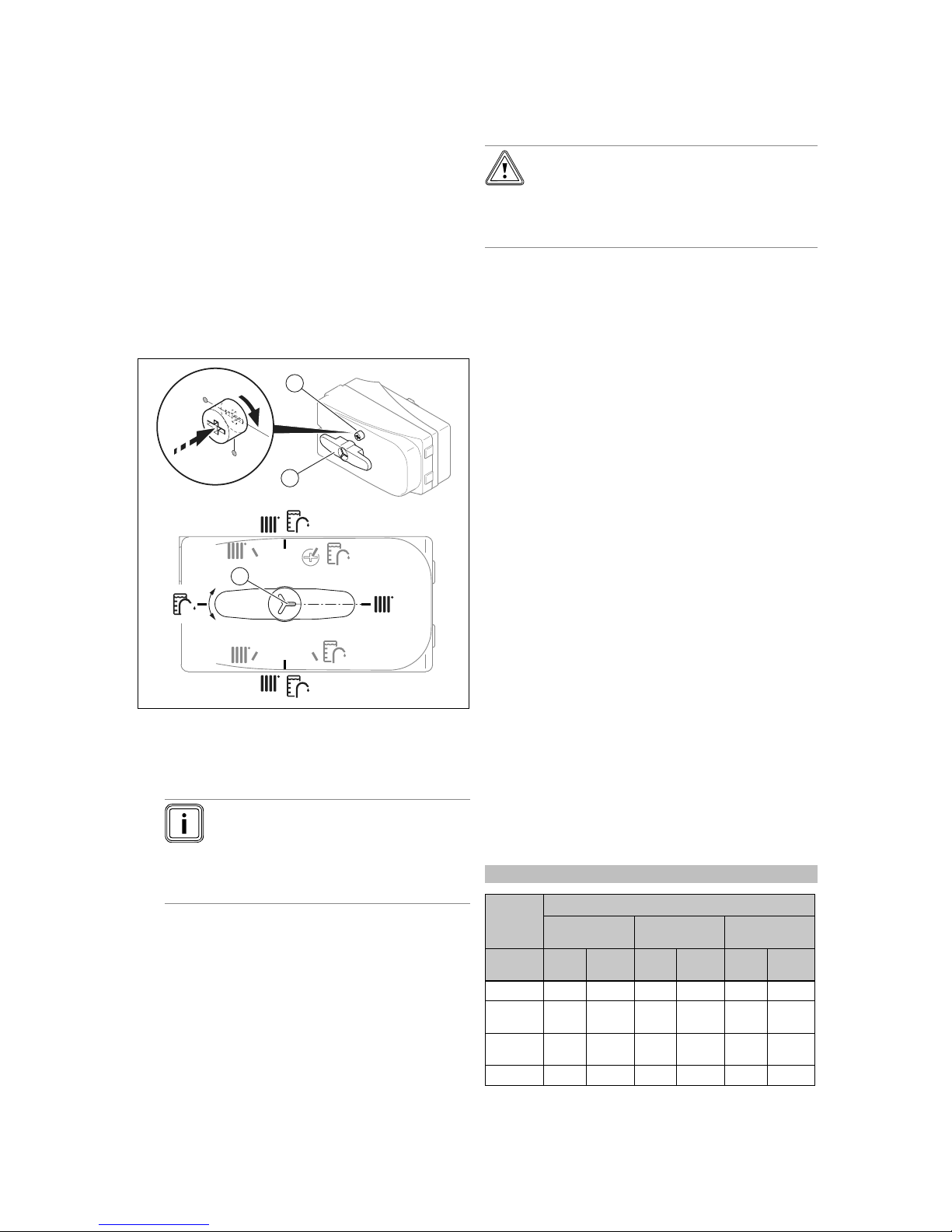
7 Start-up
34 Installation and maintenance instructions Hydraulic station 0020257319_02
▽ The settings for the function can be changed in the
current programme.
▶ Return to the programme steps in order to
change the settings or the current day.
◁ If the screed drying has not been run successfully
by day 29, the display shows the message Screed
drying ending.
▽ If a fault occurs during screed drying, the display
shows the message Fault.
▶ Select a new start day for the screed drying or
interrupt the process.
7.2 Setting the prioritising diverter valve
1. Install the selection lever from the bag of small parts on
the prioritising diverter valve.
2
1
3
MAN
AUTO
90°
2. If you want to manually set the prioritising diverter
valve, press the knob (1) and turn it 90° clockwise.
◁ You can now turn the selection lever (2) to the re-
quired position.
Note
The notch (3) along the selection lever displays the selected mode.
For example: If the notch along the selection
lever is pointing clockwise: The heating circuit is selected.
3. If you want to actuate the heating circuit, turn the selection lever to "Heating circuit".
4. If you want to actuate the domestic hot water cylinder,
turn the selection lever to "Domestic hot water cylinder".
5. If you want to actuate the heating circuit and the domestic hot water cylinder, turn the selection lever to
"Heating circuit/domestic hot water cylinder".
7.3 Checking and treating the heating
water/filling and supplementary water
Caution.
Risk of material damage due to poor-qual-
ity heating water
▶ Ensure that the heating water is of suffi-
cient quality.
▶ Before filling or topping up the installation, check the
quality of the heating water.
Checking the quality of the heating water
▶ Remove a little water from the heating circuit.
▶ Check the appearance of the heating water.
▶ If you ascertain that it contains sedimentary materials,
you must desludge the installation.
▶ Use a magnetic rod to check whether it contains mag-
netite (iron oxide).
▶ If you ascertain that it contains magnetite, clean the in-
stallation and apply suitable corrosion-protection measures, or fit a magnetic filter.
▶ Check the pH value of the removed water at 25 °C.
▶ If the value is below 8.2 or above 10.0, clean the installa-
tion and treat the heating water.
▶ Ensure that oxygen cannot get into the heating water.
Checking the filling and supplementary water
▶ Before filling the installation, measure the hardness of the
filling and supplementary water.
Treating the filling and supplementary water
▶ Observe all applicable national regulations and technical
standards when treating the filling and supplementary
water.
Provided the national regulations and technical standards
do not stipulate more stringent requirements, the following
applies:
You must treat the heating water in the following cases:
– If the entire filling and supplementary water quantity dur-
ing the operating life of the system exceeds three times
the nominal volume of the heating installation, or
– If the guideline values listed in the following table are not
met, or
– If the pH value of the heating water is less than 8.2 or
more than 10.0.
Applicability: Great Britain
Total
heating
output
Water hardness at specific system volume
1)
≤ 20 l/kW
> 20 l/kW
≤ 50 l/kW
> 50 l/kW
kW
ppm
CaCO₃
mol/m³ppm
CaCO₃
mol/m³ppm
CaCO₃
mol/
m³
< 50 < 300 < 3 200 2 2 0.02
> 50
to ≤ 200
200 2 150 1.5 2 0.02
> 200
to ≤ 600
150 1.5 2 0.02 2 0.02
> 600 2 0.02 2 0.02 2 0.02
Page 37
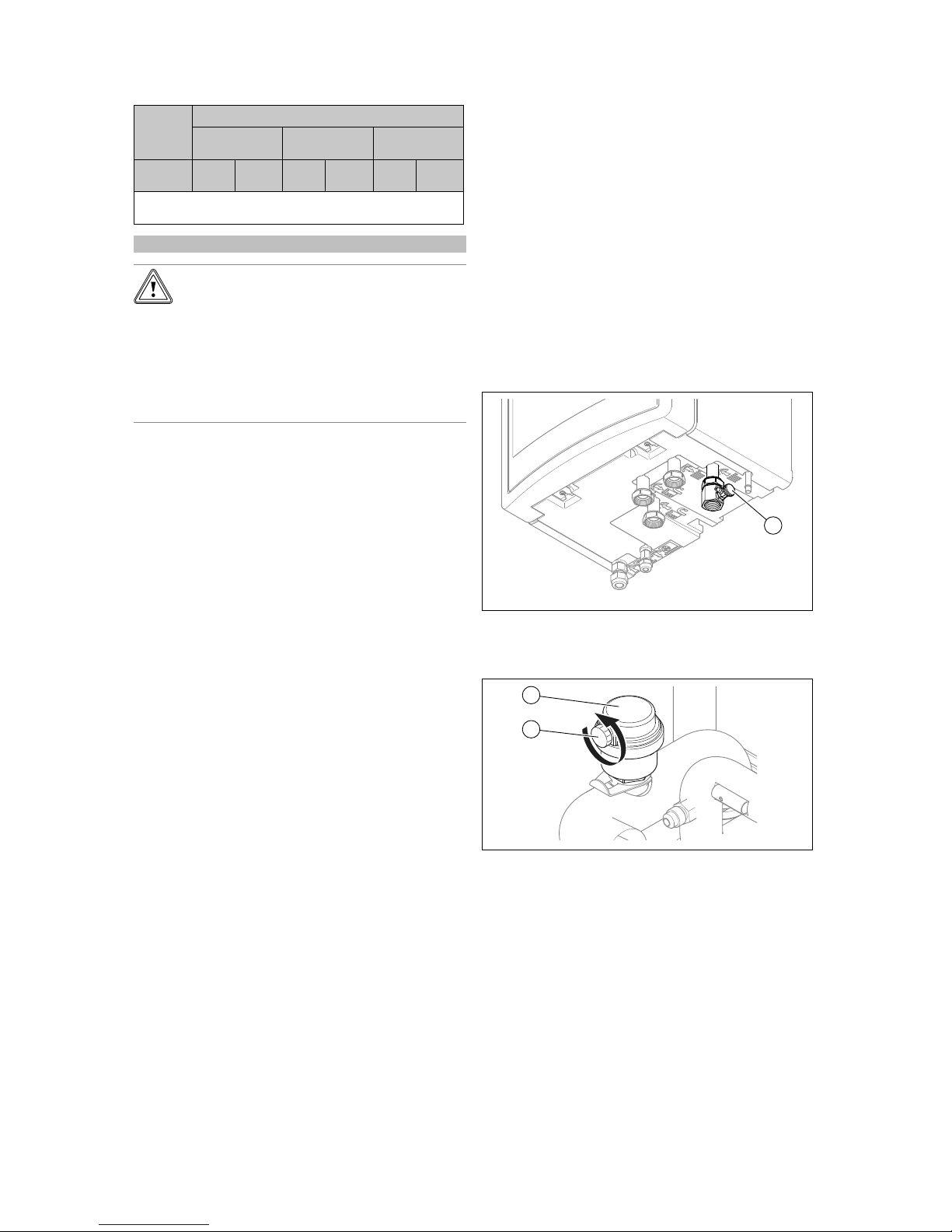
Start-up 7
0020257319_02 Hydraulic station Installation and maintenance instructions 35
Total
heating
output
Water hardness at specific system volume
1)
≤ 20 l/kW
> 20 l/kW
≤ 50 l/kW
> 50 l/kW
kW
ppm
CaCO₃
mol/m³ppm
CaCO₃
mol/m³ppm
CaCO₃
mol/
m³
1) Nominal capacity in litres/heating output; in the case of multiboiler systems, the smallest single heating output is to be used.
Applicability: Great Britain
Caution.
Risk of material damage if the heating
water is treated with unsuitable additives.
Unsuitable additives may cause changes in
the components, noises in heating mode and
possibly subsequent damage.
▶ Do not use any unsuitable antifreeze and
corrosion inhibitors, biocides or sealants.
No incompatibility with our products has been detected to
date with proper use of the following additives.
▶ When using additives, follow the manufacturer's instruc-
tions without exception.
We accept no liability for the compatibility of any additive or
its effectiveness in the rest of the heating system.
Additives for cleaning measures (subsequent
flushing required)
– Adey MC3+
– Adey MC5
– Fernox F3
– Sentinel X 300
– Sentinel X 400
Additives intended to remain permanently in the
installation
– Adey MC1+
– Fernox F1
– Fernox F2
– Sentinel X 100
– Sentinel X 200
Additives for frost protection intended to remain
permanently in the installation
– Adey MC ZERO
– Fernox Antifreeze Alphi 11
– Sentinel X 500
▶ If you have used the above-mentioned additives, inform
the end user about the measures that are required.
▶ Inform the end user about the measures required for frost
protection.
7.4 Filling and purging the heating installation
1. Flush the heating installation thoroughly prior to filling.
2. Open all of the thermostatic valves on the heating installation and, if required, all other isolation valves.
3. If no domestic hot water cylinder is connected, seal the
product's cylinder flow and cylinder return connection
with on-site plugs.
4. Check all of the connections and the entire heating installation for leaks.
5. Switch the prioritising diverter valve to manual operation
(→ Page 34) and turn the selection lever to "Heating
circuit/domestic hot water cylinder".
◁ Both valves are open and the filling procedure is
improved since the air in the system can escape.
◁ The heating circuit and the spiral immersion heater
for the domestic hot water cylinder are filled at the
same time.
1
6. Connect a filling hose to the filling device (1).
7. To do this, unscrew the screw cap from the filling device
and secure the free end of the filling hose to here.
2
1
8. Open the purging screw (2) on the automatic air vent
(1) in order to purge the product.
9. Open the filling device.
10. Open the heating water supply slowly.
11. Purge the highest radiator or underfloor heating circuit
and wait until the circuit is completely purged.
◁ The water must escape from the purging valve
without bubbles.
12. Fill with water until the manometer (on-site) shows that
the heating installation has reached a pressure of approx. 1.5 bar.
Page 38
7 Start-up
36 Installation and maintenance instructions Hydraulic station 0020257319_02
Note
If you fill the heating circuit at an external
location, you must install an additional manometer to check the pressure in the installation.
13. Close the filling device.
14. Then check the heating installation pressure again (if
required, repeat the filling procedure).
15. Remove the filling hose from the filling device and
screw the screw cap back on.
16. Set automatic mode for the prioritising diverter valve
again (→ Page 34).
◁ When the product starts up, the diverter valve auto-
matically moves to the "Heating circuit" outlet position.
7.5 Purging
1. Open the automatic air vent.
2. Start the purge programme for the building circuit P06
using: Menu Installer level 17 Test menu Check pro-
grammes Purge building circuit P06.
3. Allow the P06 function to run for 15 minutes.
◁ The programme runs for 15 minutes. For 7.5
minutes of that time, the prioritising diverter valve
is at the "heating circuit" position. The prioritising
diverter valve then switches to the "domestic hot
water cylinder" position for 7.5 minutes.
4. Once both purge programmes have finished, check
whether the pressure in the heating circuit is 1.5 bar.
◁ Top up with water if the pressure is below 1.5 bar.
7.6 Starting up the product
Caution.
Risk of material damage in the event of
frost.
If the installation is switched on when there is
ice in the lines, the installation may be mechanically damaged.
▶ You must observe the frost protection
instructions.
▶ Do not switch the installation on when
there is a risk of frost.
Note
The product does not have an on/off switch. The
product is switched on as soon as it is connected
to the power grid.
1. Use the partition that is installed on-site (e.g. fuses or
power switches) to switch on the product.
◁ The display shows the basic display.
◁ The basic display appears on the system control
display.
◁ The system's products start up.
◁ The heating and domestic hot water demand are
activated by default.
2. When you start up the heat pump system for the first
time after electrical installation, the installation assistants for the system components will start automatically.
Set the required values on the control panel of the indoor unit first, then on the optional system control and
the other system components.
7.7 Running the installation assistants
The installation assistant is launched when the product is
switched on for the first time. It provides direct access to
the most important check programmes and configuration
settings for starting up the product.
Menu → Installer level → 17 → Configuration.
Confirm the launch of the installation assistant. All heating
and domestic hot water demands are blocked whilst the installation assistant is active.
To access the next item, confirm by pressing Next in each
case.
If you do not confirm the launch of the installation assistant,
it is closed 10 seconds after you switch on the unit and the
basic display then appears.
7.7.1 Setting the language
▶
Press OK twice to confirm the set language and to avoid
unintentionally changing it.
▽ If you have accidentally set a language that you do
not understand:
▶ You can change the language as follows:
▶ Menu → Basic settings → Language.
▶ Select the required language.
▶ Confirm the selection by pressing OK.
7.7.2 Telephone number for the competent person
You can store your telephone number in the product menu.
The end user can display it in the information menu. The
telephone number can be up to 16 digits long and must not
contain any spaces. If the telephone number is shorter, end
the entry after the last digit by pressing
.
All of the digits to the right will be deleted.
7.7.3 Ending the installation assistant
▶ Once you have run through the installation assistant suc-
cessfully, confirm by pressing
.
◁ The installation assistant will close and will not launch
again when the product is next switched on.
7.8 Energy balance control
The energy balance is the integral from the difference
between the flow temperature actual value and target value,
which is added up every minute. If the set heat deficit (WE =
-60°min in heating mode) is reached, the heat pump starts.
If the supplied heat volume corresponds to the heat deficit
(integral = 0°min), the heat pump is switched off.
The energy balancing is used for heating and cooling mode.
Page 39
Start-up 7
0020257319_02 Hydraulic station Installation and maintenance instructions 37
7.9 Compressor hysteresis
The heat pump is switched on and off via the compressor
hysteresis for heating mode and also for energy balancing.
When the compressor hysteresis is above the target flow
temperature, the heat pump is switched off. When the hysteresis is below the target flow temperature, the heat pump
starts up again.
7.10 Enabling the electric back-up heater
On the system control, you can select whether the electric
back-up heater is to be used for heating mode, domestic
hot water mode or both modes. Set the maximum output for
the electric back-up heater at the indoor unit's control panel
here.
▶ Activate the internal electric back-up heater with one of
the following output levels.
▶ Ensure that the maximum output for the electric back-up
heater does not exceed the output of the fuse protection
for the household electricity system (for rated currents,
see Technical Data).
Note
Otherwise, the home's internal circuit breaker
may trigger if, when there is insufficient heat
source output, the electric back-up heater that
is not derated is switched on.
▶
You can find the output levels for the electric back-up
heater in the tables in the appendix.
5.4 kW back-up heater (→ Page 57)
8.54 kW back-up heater at 230 V (→ Page 57)
8.54 kW back-up heater at 400 V (→ Page 58)
7.11 Setting the anti-legionella function
▶ Set the anti-legionella function using the system control.
To ensure sufficient legionella protection, the electric backup heater must be activated.
7.12 Purging
You can use the installation assistant to run through the purging programmes.
▶ To do this, read the purging section. (→ Page 36)
7.13 Calling up the installer level
1. Press
and at the same time.
2. Navigate to Menu → Installer level and confirm by
pressing
(OK).
3. Set the value 17 (code) and confirm by pressing
.
7.14 Restarting the installation assistants
You can restart the installation assistant at any time by calling it up in the menu.
Menu → Installer level → Start inst. assistant.
7.15 Calling up statistics
Menu → Installer level → Test menu → Statistics
You can use this function to call up the statistics for the heat
pump.
7.16 Using check programmes
You can call up the check programmes via Menu → Installer
level → Test menu → Check programmes.
You can activate various special functions in the product by
using various check programmes.
If the product is in error condition, you cannot start any check
programmes. You can detect an error condition by the fault
symbol shown in the left bottom corner of the display. You
must first reset.
To end the check programmes, you can press Cancel at any
time.
7.17 Carrying out the actuator test
Menu → Installer level → Test menu → Sensor/actuator
test
You can check that the components of the heating installation are functioning correctly using the sensor/actuator test.
You can actuate more than one actuator at a time.
If you do not select anything to change, you can have the
current control values for the actuators and the sensor values displayed.
You can find a list of the sensor characteristic values in the
appendix.
Characteristic values for the temperature sensor, refrigeration circuit (→ Page 58)
Characteristic values for the internal temperature sensors,
hydraulic circuit (→ Page 59)
Characteristic values for the VRC DCF outdoor temperature
sensor (→ Page 61)
7.18 Starting up the optional system control
The following work for starting up the system was carried
out:
– The system control and the outdoor temperature sensor
have been installed and wired.
– Start-up of all system components (except for the system
control) is complete.
Follow the installation assistant and the operating and installation instructions for the system control.
Page 40
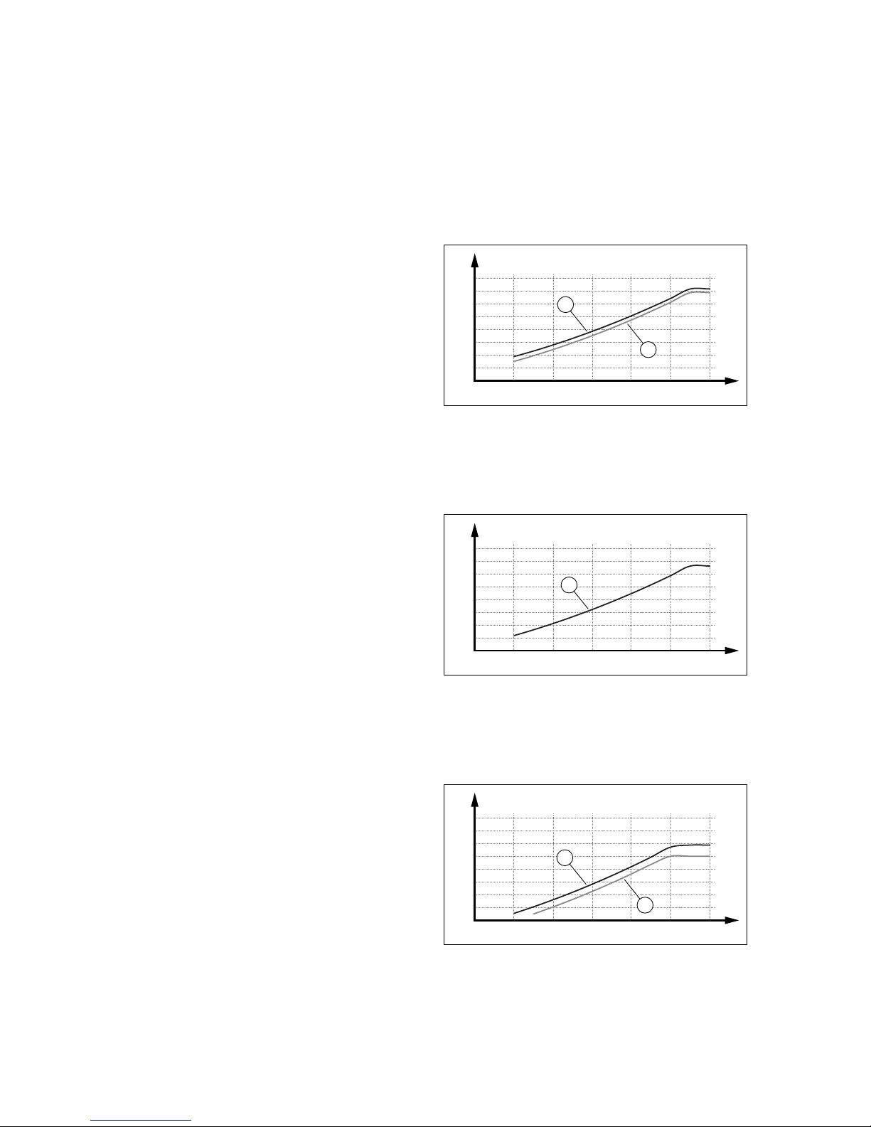
8 Operation
38 Installation and maintenance instructions Hydraulic station 0020257319_02
7.19 Display of the filling pressure in the heat
pump circuit
The product has a pressure sensor in the heating circuit and
a digital pressure display.
▶ Select Menu Live Monitor to display the filling pressure
in the heat pump circuit.
◁ To ensure that the heat pump circuit works correctly,
the filling pressure must be between 1 bar and 1.5
bar. If the heating installation extends over several
storeys, higher filling pressures may be required to
avoid air entering the heating installation.
7.20 Preventing low water pressure in the heating
circuit
▶ Remove the front casing and read the water pressure on
the product's manometer.
▶ Check whether the pressure is between 1 and 1.5 bar.
◁ If the pressure in the heating circuit is too low, add
more water using the pre-installation jig's filling
device.
7.21 Checking function and leak-tightness
Before you hand the product over to the end user:
▶ Check that the heating installation (heat generator and
system) and the domestic hot water pipes are leak-tight.
▶ Check whether the drain pipework for the purging con-
nections has been installed correctly.
8 Operation
8.1 Operating concept of the product
The operating concept and the display and setting options of
the end user level are described in the operating instructions.
9 Adapting the unit to the heating
installation
9.1 Configuring the heating installation
The installation assistant is launched when the product is
switched on for the first time. When the installation assistant
is complete, you can further adjust the parameters of the installation assistant, for example, in the Configuration menu.
To adjust the water flow rate generated by the heat pump
to match the specific installation, you can set the maximum
available pressure for the heat pump in the heating and domestic hot water mode.
You can call up these two parameters via Menu → Installer
level → Configuration.
The adjustment range is between 200 mbar and 900 mbar.
The heat pump operates at its optimum level when the nominal flow can be achieved by setting the available pressure
(Delta T = 5 K).
9.2 Remaining feed head of the product
The remaining feed head cannot be set directly. You can
limit the remaining pump head in order to adjust the on-site
pressure loss in the heating circuit.
The integrated pump attempts to reach the nominal volume
flow.
9.2.1 VWL 57/5 remaining feed head at nominal
volume flow
0
200
400
600
800
40 50 60 70 80 90 100
B
A
1
2
1 VWL 57/5,
3.5 kW/540 l/h
2 VWL 57/5, 5 kW/790 l/h
A Remaining feed head in
hPa (mbar)
B Pump output in %
9.2.2 VWL 77/5 remaining feed head at nominal
volume flow
0
200
400
600
800
40 50 60 70 80 90 100
B
A
1
1 VWL 77/5,
7 kW/1020 l/h
A Remaining feed head in
hPa (mbar)
B Pump output in %
9.2.3 VWL 127/5 remaining feed head at nominal
volume flow
0
200
400
600
800
40 50 60 70 80 90 100
B
A
1
2
1 VWL 127/5,
10 kW/1670 l/h
2 VWL 127/5,
12 kW/1850 l/h
A Remaining feed head in
hPa (mbar)
B Pump output in %
Page 41
Troubleshooting 10
0020257319_02 Hydraulic station Installation and maintenance instructions 39
9.3 Setting the flow temperature in heating mode
(with no control connected)
1. Press
( ).
◁ The display shows the flow temperature in heating
mode.
2. Change the flow temperature in heating mode by press-
ing
or .
– Max. heating mode target flow temperature: 75 ℃
3. Confirm this change by pressing
(OK).
9.4 Instructing the end user
Danger!
Risk of death from legionella.
Legionella multiply at temperatures below
60 °C.
▶ Ensure that the end user is familiar with
all of the Anti-legionella measures in order
to comply with the applicable regulations
regarding legionella prevention.
▶ Explain to the end user how the safety devices work and
where they are located.
▶ Inform the end user how to handle the product.
▶ Draw particular attention to the safety warnings, which
the end user must follow.
▶ Inform the end user that they must have the product
maintained in accordance with the specified intervals.
▶ Explain to the end user how to check the system's water
volume/filling pressure.
▶ Pass all of the instructions and documentation for the
product to the end user for safe-keeping.
10 Troubleshooting
10.1 Contacting your service partner
If you contact your service partner, please mention if possible:
– The fault code that is displayed (F.xx)
– The status code (S.xx) that is displayed by the product in
the Live Monitor
10.2 Displaying the Live Monitor (current product
status)
Menu → Live Monitor
Status codes in the display provide information on the product's current operating mode. These can be called up via
the Live Monitor menu.
Status codes (→ Page 50)
10.3 Checking fault codes
The display shows a fault code F.xxx.
Fault codes have priority over all other displays.
Fault codes (→ Page 53)
If multiple faults occur at the same time, the display shows
the corresponding fault codes for two seconds each in sequence.
▶ Eliminate the fault.
▶ To restart the product, press the reset button ( Operating
instructions).
▶ If you are unable to eliminate the fault and the fault re-
curs despite several reset attempts, contact Customer
Service.
10.4 Querying the fault memory
Menu → Installer level Fault list
The product has a fault memory. You can use this to query
the last ten faults that occurred in chronological order.
Display views:
– Number of faults that occurred
– The fault currently selected with fault number F.xxx
▶ Use the
or button to display the last ten faults that
occurred.
10.5 Resetting the fault memory
1. Press Delete.
2. Confirm that you wish to clear the fault memory by
pressing OK.
10.6 Using check programmes
You can also use the check programmes for troubleshooting.
(→ Page 37)
10.7 Resetting parameters to factory settings
▶ Select Menu → Installer level → 17 → Resets to reset
all of the parameters at the same time and to restore the
product to its factory settings.
10.8 Safety cut-out
The product has a safety cut-out.
If the safety cut-out has tripped, the cause must be eliminated and the safety cut-out replaced.
▶ See the "Fault codes" table in the appendix.
Fault codes (→ Page 53)
▶ Check the back-up heater for damage due to overheat-
ing.
▶ Check that the power supply for the power supply PCB is
working properly.
▶ Check the cabling for the power supply PCB.
▶ Check the cabling for the back-up heater.
▶ Check that all temperature sensors are working properly.
▶ Check that all other sensors are working properly.
▶ Check the pressure in the heating circuit.
▶ Check that the heating circuit pump is working properly.
▶ Check whether there is air in the heating circuit.
Page 42
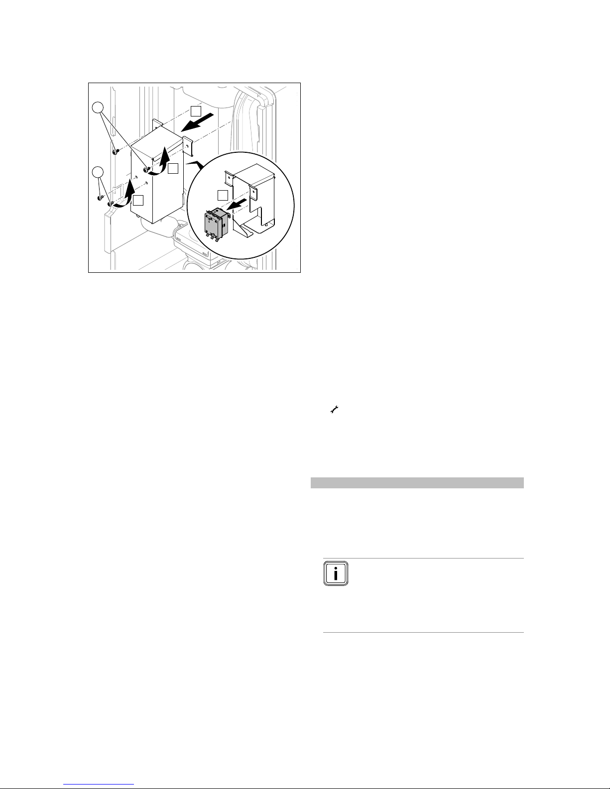
11 Inspection and maintenance
40 Installation and maintenance instructions Hydraulic station 0020257319_02
10.8.1 Replace the safety cut-out
A
B
C
D
1
2
1. Disconnect the product from the power grid and protect
it against being switched back on.
2. Remove the front casing.
3. Remove both screws (1) and remove the safety cut-out
with the retainer from the product.
4. Remove all cables from the safety cut-out. Observe the
closing mechanism for the cable duct.
5. Remove the safety cut-out from the retainer by undoing
the two screws (2).
6. Undo the nuts on the upper side of the back-up heater
and remove the temperature sensor.
7. Connect cables of the same colour to opposite sides of
each other on the safety cut-out.
8. Install the new safety cut-out in reverse order.
10.9 Preparing the repair work
1. Switch off the product.
2. Disconnect the product from the power supply.
3. Secure the product against being switched back on
again.
4. Remove the front casing.
5. Close the service valves in the heating flow and in the
heating return.
6. Close the service valve in the cold water pipe.
7. Drain the product if you want to replace water-bearing
components of the product.
8. Ensure that water does not drip on live components
(e.g. the electronics box).
9. Use only new seals.
11 Inspection and maintenance
11.1 Inspection and maintenance information
11.1.1 Inspection
The inspection is intended to determine the actual condition
of a product and compare it with the target condition. This is
done by measuring, checking and observing.
11.1.2 Maintenance
Maintenance is required in order to eliminate any deviations
between the actual condition and the target condition. This is
normally done by cleaning, setting and, if necessary, replacing individual components that are subject to wear.
11.2 Procuring spare parts
The original components of the product were also certified
by the manufacturer as part of the declaration of conformity.
If you use other, non-certified or unauthorised parts during
maintenance or repair work, this may void the conformity of
the product and it will therefore no longer comply with the
applicable standards.
We strongly recommend that you use original spare parts
from the manufacturer as this guarantees fault-free and safe
operation of the product. To receive information about the
available original spare parts, contact the contact address
provided on the back page of these instructions.
▶ If you require spare parts for maintenance or repair
work, use only the spare parts that are permitted for the
product.
11.3 Checking maintenance messages
If the
symbol is shown in the display, the product requires
maintenance work or the product is in comfort protection
mode.
▶ To obtain further information, call up the Live Monitor.
▶ Carry out the maintenance work that is listed in the table.
Maintenance messages (→ Page 52)
Condition: Lhm.XX is displayed
The product is in Comfort protection mode. The product has
detected a permanent fault and continues to run with restricted comfort.
▶ To determine which component is defective, read the
fault memory (→ Page 39).
Note
If a fault message is present, the product remains in comfort protection mode after it is
reset. After the product is reset, the fault message is displayed first before the message
Limp home mode (comfort protection) appears again.
▶ Check the component that is displayed and replace it.
Page 43
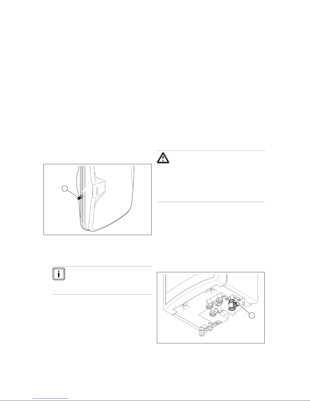
Draining 12
0020257319_02 Hydraulic station Installation and maintenance instructions 41
11.4 Observing inspection and maintenance
intervals
▶ Use the "Inspection and maintenance work" table in the
appendix.
▶ Adhere to the minimum inspection and maintenance in-
tervals. Carry out all of the work that is mentioned.
▶ Carry out maintenance work on the product at an earlier
point if the results of the inspection that was carried out
during previous maintenance make this necessary.
11.5 Preparing for inspection and maintenance
Observe the basic safety rules before carrying out inspection
and maintenance work or installing spare parts.
▶ Switch off the product.
▶ Disconnect the product from the power supply.
▶ Secure the product against being switched back on
again.
▶ When working on the product, protect all electric com-
ponents from spraying water.
▶ Remove the front casing.
11.6 Checking the admission pressure of the
expansion vessel
1
1. Close the service valves and drain the heating circuit.
(→ Page 41)
2. Measure the pre-charge pressure of the expansion ves-
sel (1) at the valve (2).
Result:
Note
The required pre-charge pressure of the
heating installation may vary depending
on the static pressure (0.1 bar per metre in
height).
Pre-charge pressure is below 0.75 bar (±0.1 bar/m)
▶ Fill the expansion vessel with nitrogen. If nitrogen is
not available, use air.
3. Fill the heating circuit. (→ Page 35)
11.7 Checking and correcting the filling pressure
of the heating installation
If the filling pressure falls below the minimum pressure, a
maintenance message is shown on the display.
– Min. heating circuit pressure: ≥ 0.05 MPa (≥ 0.50 bar)
▶ Top up the heating water in order to start up the heat
pump again; Filling and purging the heating installation
(→ Page 35).
▶ If you notice frequent pressure losses, determine and
eliminate the cause.
11.8 Checking the high-pressure switch-off
▶ Start check programme P.29 High pressure.
◁ The compressor starts and the flow rate monitoring
for the pump is deactivated.
▶ Block the heating circuit.
◁ The product is switched off by the high-pressure
switch-off.
11.9 Completing inspection and maintenance
Warning.
Risk of burns due to hot and cold com-
ponents.
There is a risk of burns from any uninsulated pipelines and from the electric backup heater.
▶ Before starting up the unit, install any cas-
ing sections that have been removed.
1. Start up the heat pump system.
2. Check that the heat pump system is working without
any problems.
12 Draining
12.1 Draining the product's heating circuit
1. Close the service valves in the heating flow and in the
heating return.
2. Remove the front casing. (→ Page 25)
1
3. Connect a hose to the filling device (1) and guide the
free end of the hose to a suitable drainage point.
Page 44
13 Decommissioning
42 Installation and maintenance instructions Hydraulic station 0020257319_02
4. Use manual actuation to move the prioritising diverter
valve to the "Heating circuit/domestic hot water cylinder"
position.
5. Open the stopcock on the filling device.
6. Open the automatic air vent.
7. Use the expansion relief valve to check whether the
heating circuit has been completely drained.
◁ Residual hot water may escape from expansion
relief valve's drain.
12.2 Draining the heating installation
1. Connect a hose to the draining point of the installation.
2. Route the free end of the hose to a suitable drainage
point.
3. Ensure that the installation's service valves are open.
4. Open the drain cock.
5. Open the purging valves on the radiators. Start from
the highest radiator and then work from the top to the
bottom.
6. Once the heating water has completely drained from
the installation, close the purging valves on all the radiators and the drain cock again.
13 Decommissioning
13.1 Temporarily decommissioning the product
1. Switch off the disconnector (circuit breaker) to which the
product is connected in the building.
2. Disconnect the product from the power supply.
13.2 Permanently decommissioning the product
1. Switch off the isolator (circuit breaker) to which the
product is connected in the building.
2. Disconnect the product from the power supply.
Caution.
Risk of material damage when extracting
refrigerant.
When extracting refrigerant, there is a risk of
material damage caused by freezing.
▶ Ensure that heating water flows through
the indoor unit's condenser (heat exchanger) or it is completely drained when
extracting refrigerant on the secondary
side.
3. Extract the refrigerant.
4. Dispose of or recycle the product and its components.
14 Recycling and disposal
14.1 Recycling and disposal
Disposing of the packaging
▶ Dispose of the packaging correctly.
▶ Observe all relevant regulations.
14.2 Disposing of the product and accessories
▶ Do not dispose of the product or the accessories with
household waste.
▶ Dispose of the product and all accessories correctly.
▶ Observe all relevant regulations.
14.3 Disposing of the refrigerant
Warning.
Risk of damage to the environment.
The product contains the refrigerant R410A.
This refrigerant must not be allowed to escape into the atmosphere. R410A is a fluorinated greenhouse gas covered by the Kyoto
Protocol, with a GWP of 2088 (GWP = Global
Warming Potential).
▶ Before the product is disposed of, have
the refrigerant which it contains completely drained into a suitable vessel so
that it can then be recycled or disposed of
in accordance with regulations.
Caution.
Risk of damage caused by defrosting.
Draining off the refrigerant generates intense
cooling of the indoor unit's plate heat exchanger, which may lead to the de-icing of
the plate heat exchanger on the heating water side.
▶ Drain the indoor unit on the heating water
side in order to prevent damage.
▶ Ensure that, during the refrigerant draining
of the plate heat exchanger on the heating
water side, there is sufficient flow-through.
▶ Ensure that the refrigerant is disposed of by a qualified
competent person.
Page 45
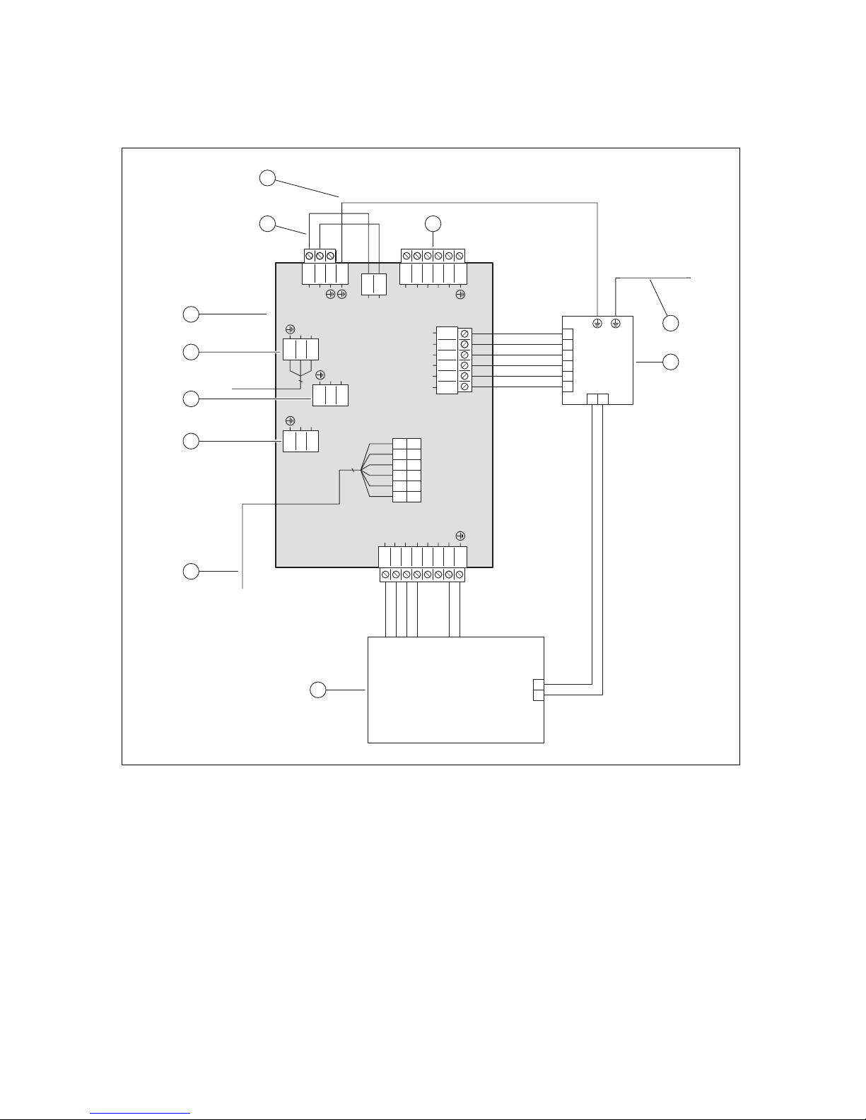
Appendix
0020257319_02 Hydraulic station Installation and maintenance instructions 43
Appendix
A Wiring diagram
12345
6
L1
L1
L2
L3
N
321
L
N
321
L
N
X302
X300X310X311
X312
X314
X313
321
L
N
3
2
1
L1
N
3
4
1
2
N
L
1
2
3
4
5
6
L2
L3
L1
L1S
L2S
L3S
L2
L3
L1
L1S
L2S
L3S
8765432
1
L3_6
L3_5
L2_4
L2_3
L1_2
L1_1
N
X301
X328
12116
5
4
2
3
1
10
9
8
7
12
6
4
9
1
8
2
3
7
10
11
5
1 Power supply PCB
2 For single power supply: 230 V bridge between
X311 and X310; for dual power supply: Replace
the bridge at X311 with the 230 V connection
3 Earthing
4 [X300] Power supply connection
5 Earth wire to X1 on the control PCB
6 [X302] Safety cut-out
7 [X301] Back-up heater
8 [X328] Data connection to the control PCB
9 [X313] Power supply for the control PCB or the op-
tional VR 70/VR 71 or the optional external current
anode
10 [X314] Power supply for the control PCB or the op-
tional VR 70/VR 71 or the optional external current
anode
11 [X312] Power supply for the control PCB or the op-
tional VR 70/VR 71 or the optional external current
anode
Page 46
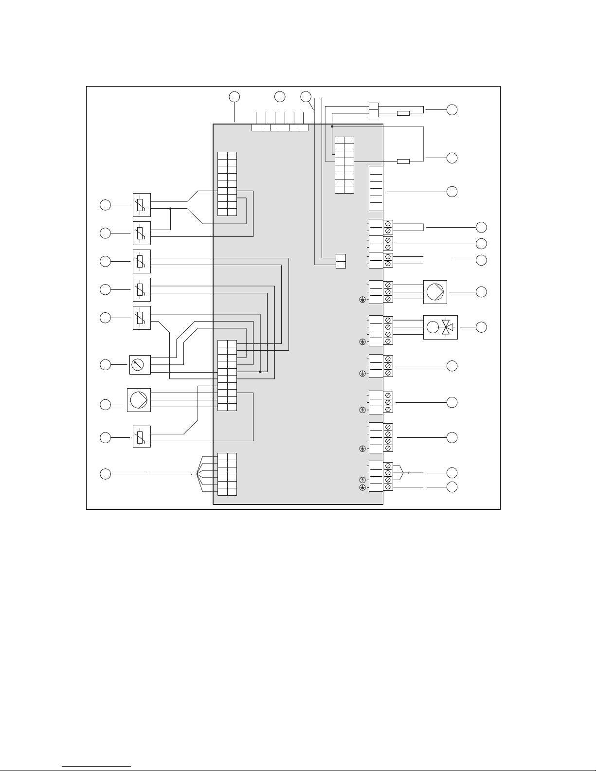
Appendix
44 Installation and maintenance instructions Hydraulic station 0020257319_02
B Control PCB
X11
S20
S21
BUS
5
6
3
4
1
2
L
N
X21
X22
1
7
8
2
918
17
16
15
14
13
12
11
10
3
4
5
6
X28
127
8
9
11
10
12
3
4
5
6
1
7
8
2
919
20
18
17
16
15
14
13
12
11
10
3
4
5
6
X16
3
1
2
L
N
X13
L
N
X15
3
4
1
2
S
L
N
X14
S
L
N
X1
L
N
X24
6
4
3
2
1
5
7
8
9
12
11
10
13
14
15
16
3
1
2
3
1
2
3
4
1
2
3
4
1
2
˽
˽
2
1
eBUS
+
-
M
˽
3
6 5 4 3 2 1
˽
˽
p
˽
˽
12
1
2
3
4
5
6
X29
1
2
X100 /
X106
3
X41
DCF
0
0
FB
AF
RF
11
10
9
8
7
1
12
13
15
14
21
19
18
17
4
5
6
2
20
22
23
24
25
16
1 Control PCB
2 [X51] Display edge connector
3 [X29] eBUS bus connection for the installed system
control
4 [X24] Coding resistor 3
5 [X24] Coding resistor 2
6 [X41] Edge connector (outdoor temperature sensor,
DCF, system temperature sensor, multi-function
input)
7 [X106/S20] Limit thermostat
8 [X106/S21] ESCO contact
9 [X106/BUS] eBUS bus connection (outdoor unit,
VRC 700, VR 70 / VR 71 )
10 [X16] Internal heating pump
11 [X15] Internal prioritising diverter valve for heating
circuit/cylinder charging
12 [X11] Multi-function output 2: Domestic hot water
circulation pump
13 [X13] Multi-function output 1
14 [X14] Multi-function output: External back-up
heater/external prioritising diverter valve
15 [X1] 230 V supply for control PCB
16 Earth wire for the power supply PCB
17 [X28] Data connection to the power supply PCB
18 [X22] Immersion heater flow temperature sensor
19 [X22] Heating pump signal
20 [X22] Pressure sensor
21 [X22] Building circuit flow temperature sensor
22 [X22] Building circuit return temperature sensor
23 [X22] Domestic hot water cylinder temperature
sensor
24 [X21] Condenser outlet temperature sensor (EEV
outlet)
25 [X21] Condenser inlet temperature sensor
Page 47
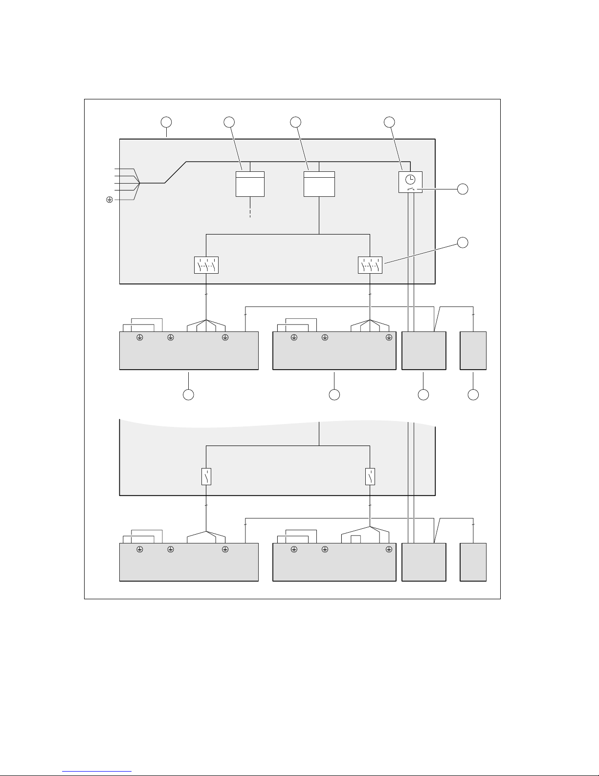
Appendix
0020257319_02 Hydraulic station Installation and maintenance instructions 45
C Basic connection diagram for the energy supply company lockout, shutdown via
connection S21
3~/400V
1~/230V
BUSS21 BUS
X106
L1L1 L2 L3 NLN
X300X311
LN
X310
kWh
L1 L2 L3 NLN
X200
BUS
X206X210
LN
X211
kWh
2
2
N
L1
L2
L3
5 5
BUSS21 BUS
X106
L1L1 L2 L3 NLN
X300X311
LN
X310
L1 L2 L3 NL N
X200
BUS
X206X210
LN
X211
2
2
3 3
1 2 3 4
5
6
78910
1 Meter/fuse box
2 Household electricity meter
3 Heat pump electricity meter
4 Ripple control receiver
5 Potential-free normally open contact, for actuating
S21, for the energy supply company lockout function
6 Disconnector (circuit breaker, fuse)
7 System control
8 Indoor unit, control PCB
9 Indoor unit, power supply PCB
10 Outdoor unit, PCB INSTALLER BOARD
Page 48
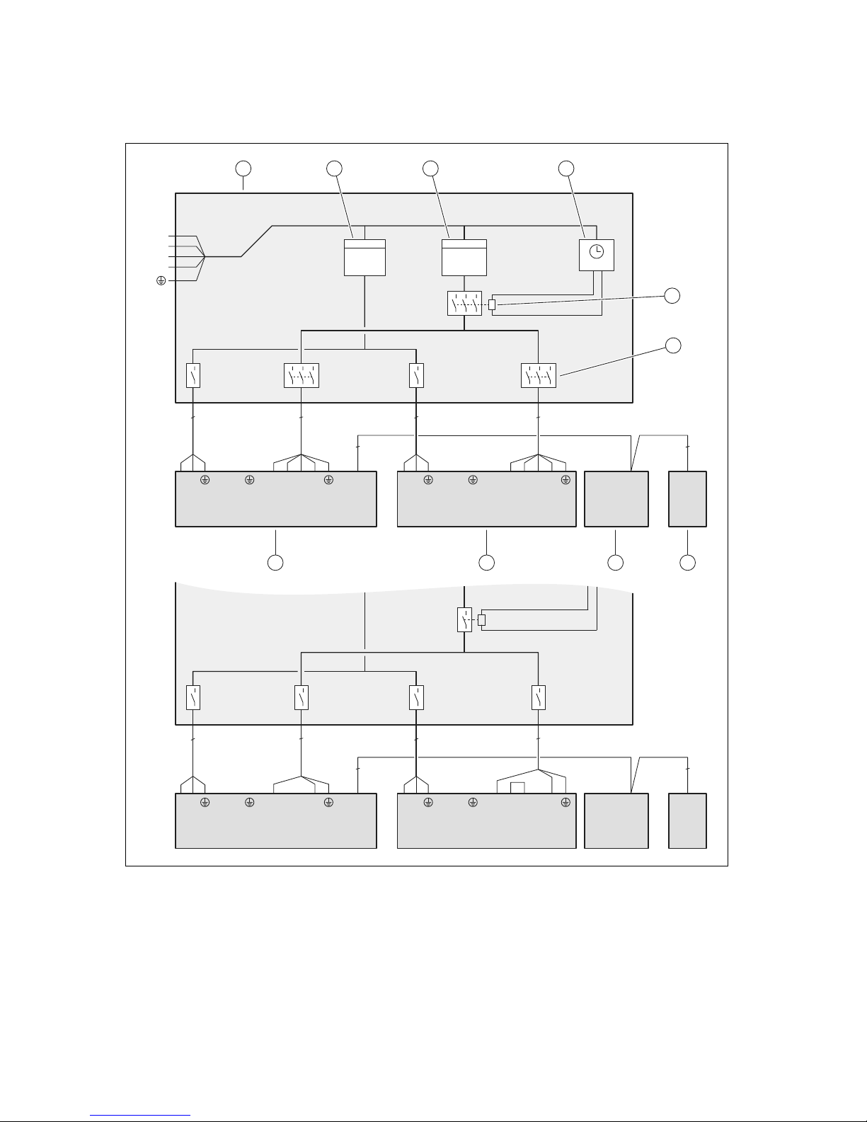
Appendix
46 Installation and maintenance instructions Hydraulic station 0020257319_02
D Basic connection diagram for the energy supply company lockout, shutdown via
partition
3~/400V 1~/230V
3
3
L1 L2 L3 NL N
X200
BUS
X206X210
LN
X211
BUSS21 BUS
X106
L1L1 L2 L3 NLN
X300X311
LN
X310
kWh
N
L1
L2
L3
kWh
L1 L2 L3 NLN
X200
BUS
X206X210
LN
X211
BUSS21 BUS
X106
L1L1 L2 L3 NLN
X300X311
LN
X310
5 5
2
2
22
3
3
3 3
1 2 3 4
5
6
78910
1 Meter/fuse box
2 Household electricity meter
3 Heat pump electricity meter
4 Ripple control receiver
5 Partition, for the energy supply company lockout
function
6 Disconnector (circuit breaker, fuse)
7 System control
8 Indoor unit, control PCB
9 Indoor unit, power supply PCB
10 Outdoor unit, PCB INSTALLER BOARD
Page 49
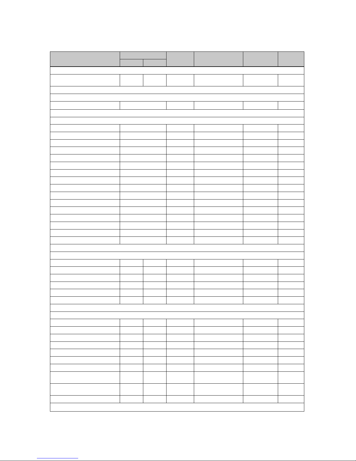
Appendix
0020257319_02 Hydraulic station Installation and maintenance instructions 47
E Installer level overview
Setting level Values Unit Increment, select, ex-
planation
Factory setting Setting
Min. Max.
Installer level →
Enter code 00 99 1 (competent person
code 17)
00
Installer level → Fault list →
F.XX – F.XX
1)
Current value
Installer level → Test menu → Statistics →
Compressor hours Current value h
Compressor starts Current value
Build. pump hours Current value h
Build. pump starts Current value
4-port valve hours Current value h
4-port valve sw. ops Current value
Fan 1: Hours Current value h
Fan 1: Starts Current value
Fan 2: Hours Current value h
Fan 2 starts Current value
EEV steps Current value
DHW PDV switch. ops Current value
Im. heater power cons. Current value kWh
Im. heater op. hours Current value h
Im. heater switch. ops Current value
No. switch. ops Current value
Installer level → Test menu → Check programmes →
P.04 Heating mode Select
P.06 Purge building circuit Select
P.11 Cooling mode Select
P.12 De-icing Select
P.27 Immersion heater Select
P.29 High pressure Select
Installer level → Test menu → Sensor/actuator test →
T.0.17 Fan 1 0 100 % 5 0
T.0.18 Fan 2 0 100 % 5 0
T.0.19 Condensate tray heater Off On On, Off
T.0.20 4-port valve Off On On, Off
T.0.21 Position: EEV 0 100 % 5 0
T.0.23 Heating coil compressor Off On On, Off
T.0.48 Air inlet temperature -40 90 ℃ 0.1
T.0.55 Compressor outlet temperature
-40 135 ℃ 0.1
T.0.56 Compressor inlet temperature
-40 90 ℃ 0.1
T.0.57 EEV outlet temperature -40 90 ℃
1)
See the overview of fault codes: Fault lists are only available, and can only be deleted, if faults have occurred.
Page 50
Appendix
48 Installation and maintenance instructions Hydraulic station 0020257319_02
Setting level Values Unit Increment, select, ex-
planation
Factory setting Setting
Min. Max.
T.0.63 High pressure 0 42.5 bar (abs) 0.1
T.0.67 High-pressure switch Off On On, Off
T.0.85 Evaporation temperature -40 90 ℃ 0.1
T.0.86 Condensation temperature -40 70 ℃ 0.1
T.0.87 Overheating target value -40 90 K 0.1
T.0.88 Overheating actual value -40 90 K 0.1
to 20 K are normal operating parameters
T.0.89 Subcooling target value -40 90 K 0.1
T.0.90 Subcooling actual value -40 90 K 0.1
T.0.93 Compressor speed 0 120 Rotation/s 1
T.0.123 Temperature switch:
Compressor outlet
Off On On, Off
T.1.01 Building circuit pump
power
0 100 % 5, off Off
T.1.02 DHW prioritising diverter
valve
Heating Domestic
hot water
Heating, Domestic hot
water
Heating
T.1.40 Flow temperature -40 90 ℃ 0.1
T.1.41 Return temperature -40 90 ℃ 0.1
T.1.42 Building circuit: Pressure 0 3 bar 0.1
T.1.43 Building circuit: Flow rate 0 4000 l/h 1
T.1.44 Cylinder temperature -40 90 ℃ 0.1
T.1.46 Lockout contact S20 Closed Open Closed, Open Closed
T.1.59 Capacitor outlet temperature
-40 90 ℃ 0.1
T.1.69 Outdoor temperature -40 90 ℃ 0.1
T.1.70 System temperature -40 90 ℃ 0.1
T.1.71 DCF status Current value No DCF signal
Validate DCF signal
Valid DCF signal
T.1.72 Lockout contact S21 Closed Open Closed, Open Open
T.1.119 MO1 output Off On Off, On Off
T.1.124 Safety cut-out immersion
heater
Closed Open Closed, Open Closed
T.1.125 MPI input Current value
T.1.126 MO2 output Off On Off, On Off
T.1.127 MO3 output Off On Off, On Off
Installer level → Configuration →
Language Current language Languages available for
selection
02 English
Contact details → Telephone
number
Phone number 0–9
MO relay Fault signal
Ext. immersion heater
DHW 3WV
None
Compr.start heat. from −999 9 °min 1 −60
Compr.start cool. from 0 999 °min 1 60
Compressor hyster. 3 15 K Applies for heating
mode only:
1
7
1)
See the overview of fault codes: Fault lists are only available, and can only be deleted, if faults have occurred.
Page 51
Appendix
0020257319_02 Hydraulic station Installation and maintenance instructions 49
Setting level Values Unit Increment, select, ex-
planation
Factory setting Setting
Min. Max.
Max. rem. feed head 200 1100 mbar 10 1100
DHW mode 0 = ECO 1 = Nor-
mal
0, 1 0
Max. anti-cycl. time 0 9 h 1 5
Reset anti-cycl. time → Anti-cycl.
time after pow. supp. switch-on
0 120 min 1 0
Im. heater outp. range External 9 kW 5 kW and 7 kW: 230 V
and 400 V:
1–6: 1 kW – 6 kW
12 kW, 230 V:
1–6: 1 kW – 6 kW
12 kW, 400 V:
1–9: 1 kW – 9 kW
6 or 9
Compr. current limit VWL 58/5 IS + VWL
78/5 IS: 13 - 16 A
VWL 128/5 IS: 20 - 25
A
Compr. noise reduct. 40 60 % 1 40
Soft modulation Off On Off, On On
Only for products with cooling:
Cooling technology
None Active
cooling
None, active cooling None
Software version Current value of the
control PCB (HMU
indoor unit xxxx, HMU
outdoor unit xxxx) and
the display (AI xxxx)
xxxx.xx.xx
Installer level → Resets →
Statistics → Reset statistics? Yes, No No
Statistics → Reset fault? Yes, No No
Factory settings → Restore factory settings
Yes, No No
Installer level → Start inst. assistant →
Language Languages available for
selection
02 English
Syst. control avail.? Yes no Yes, No
Im. heater power supp. 230 V 400 V
Im. heater outp. range External 9 kW 5 kW and 7 kW: 230 V
and 400 V:
1–6: 1 kW – 6 kW
12 kW, 230 V:
1–6: 1 kW – 6 kW
12 kW, 400 V:
1–9: 1 kW – 9 kW
6 or 9
Cooling technology No cool-
ing
Active
cooling
Compr. current limit 13 25 A 1
5 – 7 kW: 13 – 16 A
12 kW: 20 – 25 A
MO relay None, fault signal, ext.
immersion heater, DHW
3WV
None
Check program: Purge building
circuit
Yes no Yes, No no
1)
See the overview of fault codes: Fault lists are only available, and can only be deleted, if faults have occurred.
Page 52
Appendix
50 Installation and maintenance instructions Hydraulic station 0020257319_02
Setting level Values Unit Increment, select, ex-
planation
Factory setting Setting
Min. Max.
Contact details Telephone number
Phone number 0–9 Empty
End the installation assistant? Yes, back
1)
See the overview of fault codes: Fault lists are only available, and can only be deleted, if faults have occurred.
F Status codes
Statuscode Meaning
S.34 Heating mode: Frost protection
If the measured outdoor temperature falls below XX °C, the temperature of the heating circuit's flow
and return is monitored. If the temperature difference exceeds the set value, the pump and compressor are started without a heat demand.
S.100 Standby There is no heat demand or cooling demand. Standby 0: Outdoor unit. Standby 1: Indoor unit
S.101 Heating: Compressor
shutdown
The heat demand is met, the demand is ended by the system control and the heat deficit is offset.
The compressor is switched off.
S.102 Heating: Compressor
blocked
The compressor is blocked for heating mode because the heat pump is outside of its operating limits.
S.103 Heating: Prerun The start conditions for the compressor in heating mode are checked. Start the other actuators for
heating mode.
S.104 Heating: Compressor
active
The compressor works in order to meet the heat demand.
S.107 Heating: Overrun The heat demand is met, the compressor is switched off. The pump and fan overrun.
S.111 Cooling: Compressor
shutdown
The cooling demand is met, the demand is ended by the system control. The compressor is switched
off.
S.112 Cooling: Compressor
blocked
The compressor is blocked for cooling mode because the heat pump is outside of its operating limits.
S.113 Cooling: Compressor
mode prerun
The start conditions for the compressor in cooling mode are checked. Start the other actuators for
cooling mode.
S.114 Cooling: Compressor
active
The compressor works in order to meet the cooling demand.
S.117 Cooling: Compressor
mode overrun
The cooling demand is met, the compressor is switched off. The pump and fan overrun.
S.125 Heating: Immersion
heater active
The immersion heater is used in heating mode.
S.132 Domestic hot water:
Compressor blocked
The compressor is blocked for domestic hot water mode because the heat pump is outside of the
operating limits.
S.133 Domestic hot water:
Prerun
The start conditions for the compressor in domestic hot water mode are checked. Start the other actuators for domestic hot water mode.
S.134 Domestic hot water:
Compressor active
The compressor works in order to meet the domestic hot water demand.
S.135 Domestic hot water:
Immersion heater active
The immersion heater is used in domestic hot water mode.
S.137 Domestic hot water:
Overrun
The domestic hot water demand is met, the compressor is switched off. The pump and fan overrun.
S.141 Heating: Immersion
heater shutdown
The heat demand is met, the immersion heater is switched off.
S.142 Heating: Immersion
heater blocked
The immersion heater is blocked for heating mode.
S.151 Domestic hot water:
Immersion heater shutdown
The domestic hot water demand is met, the immersion heater is switched off.
S.152 Domestic hot water:
Immersion heater blocked
The immersion heater is blocked for domestic hot water mode.
S.173 Anti-cycling time for
the energy supply company
The mains voltage supply is interrupted by the energy supply company. The maximum anti-cycling
time is set in the configuration.
S.202 Check programme: Purging of building circuit active
The building circuit pump is actuated in cyclical intervals, alternately in heating mode and domestic
hot water mode.
S.203 Actuator test active The sensor and actuator test is currently operating.
S.212 Connection fault: Control not recognised
System control was previously detected but the connection is broken. Check the eBUS connection to
the system control. It can only be operated with the heat pump's additional functions.
Page 53
Appendix
0020257319_02 Hydraulic station Installation and maintenance instructions 51
Statuscode Meaning
S.240 Compr. oil temp. too
low, environment too cold
The compressor heating is switched on. The unit does not start up.
S.252 Fan unit 1: Fan blocked If the fan speed is 0 rpm, the heat pump is switched off for 15 minutes and then restarted. If the fan
does not start up after four unsuccessful restarts, the heat pump is switched off and the fault message F.718 is displayed.
S.255 Fan unit 1: Air inlet
temp. too high
The compressor does not start because the outdoor temperature at the fan is above the operating
limits. Heating mode: > 43 °C. Domestic hot water mode: > 43 °C. Cooling mode: > 46 °C.
S.256 Fan unit 1: Air inlet
temp. too low
The compressor does not start because the outdoor temperature at the fan is below the operating
limits. Heating mode: < -20 °C. Domestic hot water mode: < -20 °C. Cooling mode: < 15 °C.
S.260 Fan unit 2: Fan blocked If the fan speed is 0 rpm, the heat pump is switched off for 15 minutes and then restarted. If the fan
does not start up after four unsuccessful restarts, the heat pump is switched off and the fault message F.785 is displayed.
S.272 Building circuit: Remaining feed head limit active
The remaining feed head that is set under the configuration is reached.
S.273 Building circuit: Flow
temperature too low
The flow temperature that is measured in the building circuit is below the operating limits.
S.275 Building circuit: Flow
rate too low
Building circuit pump defective. All consumers in the heating system are closed. Flow rate is too low
for recording with the volume flow sensor (< 120 l/h). The values fall below the specific minimum
volume flows. Check that the dirt filter is permeable. Check the stopcocks and thermostatic valves.
Ensure that the flow rate is at least 35% of the nominal flow rate. Check that the building circuit pump
functions correctly.
S.276 Building circuit: Lockout contact S20 open
Contact S20 is open at the heat pump's main PCB. Incorrect limit thermostat setting. Flow temperature sensor (heat pump, gas-fired boiler, system sensor) measures values that deviate downwards.
Adjust the maximum flow temperature for the direct heating circuit via the system control (observe
the upper switch-off threshold for the boilers). Adjust the set value for the limit thermostat. Check the
sensor values
S.277 Building circuit: Pump
fault
If the building circuit pump is inactive, the heat pump is switched off for 10 minutes and is then restarted. If the building circuit pump does not start up after three unsuccessful restarts, the heat pump is
switched off and the fault message F.788 is displayed.
S.280 Freq. converter fault:
Compressor
The compressor motor or wiring is defective.
S.281 Freq. converter fault:
Mains voltage
There is overvoltage or undervoltage.
S.282 Freq. converter fault:
Overheating
If the cooling of the frequency inverter is not sufficient, the heat pump is switched off for one hour and
then restarted again. If the cooling is not sufficient after three unsuccessful restarts, the heat pump is
switched off and the fault message F.819 is displayed.
S.283 De-icing time too long If the de-icing takes longer than 15 minutes, the heat pump is restarted. If the time for the de-icing is
still not sufficient after three unsuccessful restarts, the heat pump is switched off and the fault message F.741 is displayed. ► Check whether sufficient thermal energy is available from the building circuit.
S.284 De-icing flow temperature too low
If the flow temperature is below 5 °C, the heat pump is restarted. If the flow temperature is still not
sufficient after three unsuccessful restarts, the heat pump is switched off and the fault message F.741
is displayed. ► Check whether sufficient thermal energy is available from the building circuit.
S.285 Compressor outlet temperature too low
Compressor outlet temperature is too low
S.286 Hot gas temperature
switch open
If the hot gas temperature is above 119 °C +5 K, the heat pump is switched off for one hour and then
restarted again. If the hot gas temperature has not fallen after three unsuccessful restarts, the heat
pump is switched off and the fault message F.823 is displayed.
S.287 Fan 1: Wind Before starting, the fan rotates at a speed of 50 rpm or higher. This may be caused by a strong out-
side wind.
S.288 Fan 2: Wind Before starting, the fan rotates at a speed of 50 rpm or higher. This may be caused by a strong out-
side wind.
S.289 Current limit active The outdoor unit's power consumption is reduced, the compressor speed is reduced. The com-
pressor's operating current exceeds the limit value that is set under the configuration. (for 3 kW,
5 kW, 7 kW units: <16 A; for 10 kW, 12 kW units: <25 A)
S.290 Switch-on delay active The compressor's switch-on delay is active.
S.302 High-pressure switch
open
If the pressure in the refrigerant circuit exceeds the operating limit, the heat pump is switched off for
15 minutes and is then restarted again. If the pressure remains too high after four unsuccessful restarts, the fault message F.731 is displayed.
S.303 Compressor outlet temperature too high
The operating characteristics have been exited. The heat pump is restarted.
S.304 Evaporation temperature too low
The operating characteristics have been exited. The heat pump is restarted.
Page 54
Appendix
52 Installation and maintenance instructions Hydraulic station 0020257319_02
Statuscode Meaning
S.305 Condensation temperature too low
The operating characteristics have been exited. The heat pump is restarted.
S.306 Evaporation temperature too high
The operating characteristics have been exited. The heat pump is restarted.
S.308 Condensation temperature too high
The operating characteristics have been exited. The heat pump is restarted.
S.312 Building circuit: Return
temperature too low
Return temperature in the building circuit too low for compressor to start. Heating: Return temperature
< 5 °C. Cooling: Return temperature < 10 °C. Heating: Check that the 4-port diverter valve works correctly.
S.314 Building circuit: Return
temperature too high
Return temperature in the building circuit too high for the compressor to start. Heating: Return temperature > 56 °C. Cooling: Return temperature > 35 °C. Cooling: Check that the 4-port diverter valve
works correctly. Check the sensors.
S.351 Immersion heater: Flow
temp. too high
The flow temperature at the immersion heater is too high. Flow temperature > 75 °C. The heat pump
is switched off.
S.516 De-icing mode active The heat pump de-ices the outdoor unit's heat exchanger. The heating mode is interrupted. The max-
imum de-icing time is 16 minutes.
S.575 Frequency converter:
Internal fault
An internal electronics fault is present on the outdoor unit's inverter PCB. If this occurs three times,
fault message F.752 appears.
S.581 Connection fault: Frequency converter not recognised
Missing communication between the frequency converter and the outdoor unit's PCB. After this occurs three times, fault message F.753 appears.
S.590 Fault: 4-port valve position not correct
The 4-port diverter valve does not move fully to the heating or cooling position.
G Maintenance messages
Code Meaning Cause
Remedy
M.23 Status external current anode – External current anode not recog-
nised
– If required, check for a cable break
M.32 Building circuit: Pressure low – Pressure loss in the building circuit
due to leakages or air pockets
– Building circuit pressure sensor is
defective
– Check the building circuit for leaks,
top up with heating water and purge
– Check the plug contact on the PCB
and on the cable harness; check
that the pressure sensor is working
correctly and, if required, replace the
pressure sensor
M.200 Building circuit 2: Low pressure – Pressure loss in the building circuit
due to leakages or air pockets
– Building circuit pressure sensor is
defective
– Check the building circuit for leaks,
top up with heating water and purge
– Check the plug contact on the PCB
and on the cable harness; check
that the pressure sensor is working
correctly and, if required, replace the
pressure sensor
M.201 Sensor fault: Cylinder temperature – Cylinder temperature sensor defect-
ive
– Check the plug contact on the PCB
and on the cable harness; check that
the sensor is working correctly and,
if required, replace the sensor
M.202 Sensor fault: System temperature – System temperature sensor defective – Check the plug contact on the PCB
and on the cable harness; check that
the sensor is working correctly and,
if required, replace the sensor
M.203 Connection fault: Disp. not recog-
nised
– Display defective
– Display not connected
– Check the quality of the plug contact
on the PCB and on the cable harness
– Replace the display, if required
Page 55
Appendix
0020257319_02 Hydraulic station Installation and maintenance instructions 53
H Comfort protection mode
Code Meaning Description Remedy
200 Sensor fault: Temp. air inlet Still possible to operate with existing,
functional outdoor temperature sensor
Replace the air inlet sensor
I Fault codes
In the event of faults which are caused by components in the refrigerant circuit, inform customer service.
Code Meaning Cause
Remedy
F.022 Water pressure too low – Pressure loss in the building circuit
due to leakages or air pockets
– Building circuit pressure sensor
defective
– Check the building circuit for leaks
– Top up with water, purge
– Check the quality of the plug contact
on the PCB and on the cable harness
– Check that the pressure sensor is
working correctly
– Replace the pressure sensor
F.042 Fault: Coding resistor – Coding resistor damaged or not set – Check that the coding resistor is
positioned correctly and, if required,
replace it.
F.073 Sensor fault: Build. circ. pressure – The sensor is not connected or the
sensor input has short-circuited
– Check and, if required, replace the
sensor
– Replace the cable harness
F.514 Sensor fault: Compr. inlet temp.
– The sensor is not connected or the
sensor input has short-circuited
– Check and, if required, replace the
sensor
– Replace the cable harness
F.517 Sensor fault: Compr. outlet temp. – The sensor is not connected or the
sensor input has short-circuited
– Check and, if required, replace the
sensor
– Replace the cable harness
F.519 Sensor fault: Building circuit re-
turn temp.
– The sensor is not connected or the
sensor input has short-circuited
– Check and, if required, replace the
sensor
– Replace the cable harness
F.520 Sensor fault: Building circuit flow
temp.
– The sensor is not connected or the
sensor input has short-circuited
– Check and, if required, replace the
sensor
– Replace the cable harness
F.526 Sensor fault: EEV outlet temp. – The sensor is not connected or the
sensor input has short-circuited
– Check and, if required, replace the
sensor
– Replace the cable harness
F.546 Sensor fault: High pressure – Sensor not connected or sensor
input has short-circuited
– Check the sensor (e.g. using an in-
stallation aid), and replace if necessary
– Replace the cable harness
F.582 Fault: EEV – EEV is not connected correctly or
there is a cable break to the coil
– Check the plug connections and, if
required, replace the coil from the
EEV
F.585 Sensor fault: Capac. outlet temp. – The sensor is not connected or the
sensor input has short-circuited
– Check and, if required, replace the
sensor
– Replace the cable harness
F.718 Fan unit 1: Fan blocked – There is no confirmation signal stat-
ing that the fan is rotating
– Check the air route and, if required,
remove any blockages
F.729 Compressor outlet temperature
too low
– The compressor outlet temperature
is lower than 0 °C for more than 10
minutes or the compressor outlet
temperature is lower than -10 °C
even though the heat pump is in the
operating characteristics.
– Checking the high-pressure sensor
– Checking that the EEV is working
correctly
– Checking for condensate leaking
from the temperature sensor (undercooling)
– Check whether the 4-port diverter
valve is in the intermediate position
– Checking the refrigerant volume for
overfilling
Page 56

Appendix
54 Installation and maintenance instructions Hydraulic station 0020257319_02
Code Meaning Cause
Remedy
F.731 High-pressure switch open – Refrigerant pressure too high. The
integrated high-pressure switch
in the outdoor unit has tripped at
41.5 bar (g) or 42.5 bar (abs)
– Insufficient energy output via the
condenser
– Purging the building circuit
– Too low a volume flow as a result
of closing single room controls in an
underfloor heating system
– Check that the dirt filter that is in
place is permeable
– Refrigerant flow rate too low (e.g.
electronic expansion valve defective,
4-port diverter valve is mechanically
blocked, filter is blocked). Inform
customer service.
– Cooling mode: Check the fan unit for
dirt
– Check the high-pressure switch and
high-pressure sensor
F.732 Compressor outlet temperature
too high
The compressor outlet temperature is
above 130 °C:
– Application limits exceeded
– EEV does not work or does not open
correctly
– Refrigerant volume too low (frequent
defrosting due to extremely low
evaporation temperatures)
– Check the compressor inlet sensor
and outlet sensor
– Check the compressor outlet temper-
ature sensor (TT135)
– Check the EEV (does the EEV
move to the limit stop? Use the
sensor/actuator test)
– Check the refrigerant volume (see
Technical data)
– Carry out a leak-tightness test
– Check whether the service valves on
the outdoor unit are open.
F.733 Evaporation temperature too low – Insufficient air volume flow through
the outdoor unit's heat exchanger
(heating mode) leads to an insufficient energy input in the environment
circuit (heating mode) or building circuit (cooling mode)
– Refrigerant volume too low
– If the building circuit contains ther-
mostatic valves, check that they are
suitable for cooling mode (check
volume flow in cooling mode)
– Check the fan unit for dirt
– Check the EEV (does the EEV
move to the limit stop? Use the
sensor/actuator test)
– Check the compressor inlet sensor
– Check the refrigerant volume
F.734 Condensation temperature too low – The temperature in the heating
circuit is too low, outside of the
operating characteristics
– Refrigerant volume too low
– Check the EEV (does the EEV
move to the limit stop? Use the
sensor/actuator test)
– Check the compressor inlet sensor
– Check the refrigerant filling volume
(see technical data)
– Check whether the 4-port diverter
valve is in an intermediate position
and is not correctly switched
– Checking the high-pressure sensor
– Check the pressure sensor in the
heating circuit
F.735 Evaporation temperature too high – Temperature in the environment
circuit (heating mode) or building
circuit (cooling mode) too high for
compressor operation
– Feed-in of external heat into the
environment circuit due to increased
fan speed
– Check the system temperatures
– Check the refrigerant filling volume
for overfilling
– Check the EEV (does the EEV
move to the limit stop? Use
sensor/actuator test)
– Check the sensor for the evaporation
temperature (depending on the
position of the 4-port diverter valve)
– Check the volume flow in cooling
mode
– Check the air volume flow in heating
mode
Page 57

Appendix
0020257319_02 Hydraulic station Installation and maintenance instructions 55
Code Meaning Cause
Remedy
F.737 Condensation temperature too
high
– Temperature in the environment
circuit (cooling mode) or building
circuit (heating mode) too high for
compressor operation
– Feed-in of external heat into the
building circuit
– Refrigerant circuit overfilled
– Insufficient flow rate in the building
circuit
– Reduce or stop the external heat
that is entering
– Check the back-up heater (heats
up even though it is off in the
sensor/actuator test?)
– Check the EEV (does the EEV
move to the limit stop? Use the
sensor/actuator test)
– Check the compressor outlet sensor,
compressor outlet temperature
sensor (TT135) and high pressure
sensor
– Check the refrigerant filling volume
for overfilling
– Check whether the service valves on
the outdoor unit are open.
– Check the air volume flow in cooling
mode for sufficient flow rate
– Checking the heating pump
– Check the building circuit flow rate
F.741 Building circuit: Return temp. too
low
– During the de-icing, the return tem-
perature falls below 13 °C
– Ensure the minimum installation
volume is maintained; if required,
install a series return cylinder
– The fault message is displayed until
the return temperature increases to
above 20 °C.
– Activate the electric back-up heater
in the product's control panel and
in the system control in order to
increase the return temperature. The
compressor is blocked while the fault
message is present.
F.752 Fault: Frequency converter – Internal electronics fault on the in-
verter PCB
– Mains voltage outside of 70 V–282 V
– Check the integrity of the power sup-
ply cables and compressor connection cables
The plugs must audibly click into
place.
– Check the cable
– Check the mains voltage
The mains voltage must be between
195 V and 253 V.
– Check the phases
– Replace the frequency converter, if
required
F.753 Connection fault: Freq. conv.
n.recogn.
– Missing communication between the
frequency converter and the outdoor
unit's control PCB
– Check the integrity of the cable
harness and plug connection and,
if required, replace them
– Check the frequency converter by
actuating the compressor safety
relay
– Read the assigned parameters for
the frequency converter and check
whether values are displayed
F.755 Fault: 4-port valve position not
correct
– Incorrect position of the 4-port di-
verter valve. If, in heating mode, the
flow temperature is lower than the
return temperature in the building circuit.
– The temperature sensor in the elec-
tronic expansion valve environment
circuit displays an incorrect temperature.
– Check the 4-port diverter valve (is an
audible switching available? Use the
sensor/actuator test)
– Check that the coil is positioned
correctly on the 4-port valve
– Check the cable harness and plug
connections
– Check the temperature sensor in the
electronic expansion valve environment circuit
F.774 Sensor fault: Air inlet temp. – The sensor is not connected or the
sensor input has short-circuited
– Check and, if required, replace the
sensor
– Replace the cable harness
Page 58
Appendix
56 Installation and maintenance instructions Hydraulic station 0020257319_02
Code Meaning Cause
Remedy
F.785 Fan unit 2: Fan blocked – There is no confirmation signal stat-
ing that the fan is rotating
– Check the air route and, if required,
remove any blockages
F.788 Building circuit: Pump fault – The electronics system of the high-
efficiency pump has detected a
fault (e.g. dry running, blockage,
overvoltage, undervoltage) and has
switched off and locked the pump.
– Switch the heat pump off for at least
30 seconds (no current)
– Check the quality of the plug contact
on the PCB
– Check that the pump functions cor-
rectly
– Purging the building circuit
– Check that the dirt filter that is in
place is permeable
F.817 Freq. converter fault: Compressor – Defect in the compressor (e.g. short
circuit)
– Defect in the frequency converter
– Connection cable to the compressor
is defective or loose
– Measure the winding resistance in
the compressor
– Measure the frequency converter
output between the three phases, (it
must be > 1 kΩ)
– Check the cable harness and plug
connections
F.818 Freq. converter fault: Mains
voltage
– Incorrect mains voltage for operating
the frequency converter
– Shutdown via the energy supply
company
– Measure and, if required, correct the
mains voltage
The mains voltage must be between
195 V and 253 V.
F.819 Freq. converter fault: Overheating – Internal overheating of the frequency
converter
– Allow the frequency converter to cool
and restart the product
– Check the frequency converter's air
route
– Check that the fan is working cor-
rectly
– The maximum environmental tem-
perature of the outdoor unit (46 °C)
has been exceeded.
F.820 Connection fault: Building circuit
pump
– Pump does not report any signal
back to the heat pump
– Check the cable to the pump for
defects and, if required, replace it
– Replace the pump
F.821 Sensor fault: Immers. heater flow
temp.
– The sensor is not connected or the
sensor input has short-circuited
– Both of the flow temperature sensors
in the heat pump are defective
– Check and, if required, replace the
sensor
– Replace the cable harness
F.823 Hot gas temperature switch open – The hot gas thermostat shuts down
the heat pump if the temperature
in the refrigerant circuit is too high.
Following a waiting period, the heat
pump attempts to start once more.
After three failed start attempts
in succession, a fault message is
displayed.
– Max. refrigerant circuit temperature:
130 °C
– Waiting period: 5 mins (after it first
occurs)
– Waiting period: 30 mins (after it
occurs a second time and any other
time after that)
– The fault counter is reset if both of
the following conditions are met:
– Heat requirement without switch-
ing off prematurely
– 60 mins uninterrupted operation
– Check the EEV
– Replace the dirt filter in the refrigera-
tion circuit, if required
F.825 Sensor fault: Capac. inlet temp. – Refrigerant circuit temperature
sensor (vapour-forming) not connected or the sensor input has shortcircuited
– Check and, if required, replace the
sensor and cable
Page 59
Appendix
0020257319_02 Hydraulic station Installation and maintenance instructions 57
Code Meaning Cause
Remedy
F.1100 Immersion heater: Safety cut-out
open
The safety cut-out on the electric backup heater is open due to:
– Insufficient volume flow or air in the
building circuit
– The immersion heater is operated
when the building circuit is not filled
– Immersion heater operation at flow
temperatures above 95 °C trips the
safety fuse of the safety cut-out and
requires that the fuse be replaced
– Feed-in of external heat into the
building circuit
– Check the circulation in the building
circuit pump
– If required, open the stopcocks
– Replace the safety cut-out
– Reduce or stop the external heat
that is entering
– Check that the dirt filter that is in
place is permeable
F.1117 Compressor: Phase failure – Defective fuse
– Incorrect electrical connections
– Mains voltage too low
– Compressor/low tariff power supply
not connected
– Blocked by energy supply company
for over three hours
– Check the fuse
– Checking the electrical connections
– Check the voltage at the heat pump
electrical connection
– Reduce energy supply company
anti-cycling time to under three hours
F.1120 Immersion heater: Phase failure – Electric back-up heater defective
– Poorly tightened electrical connec-
tions
– Mains voltage too low
– Check the electric back-up heater
and its power supply
– Check the electrical connections
– Measure the voltage at the electrical
connection for the electric back-up
heater
F.9998 Connection fault: Heat pump – eBUS cable not connected or con-
nected incorrectly
– Outdoor unit without supply voltage
– Check the connection pipes between
the power supply PCB and control
PCB on the indoor and outdoor unit
J 5.4 kW back-up heater
Applies for products with a heat output of 5 kW and 7 kW
Internal control of the output
levels
Power consumption Set value
0 0.0 kW
1 0.9 kW 1 kW
2 1.1 kW
3 1.7 kW
4 2.0 kW 2 kW
5 2.8 kW 3 kW
6 3.7 kW 4 kW
7 4.5 kW 5 kW
8 5.4 kW 6 kW
K 8.54 kW back-up heater at 230 V
Applies for products with a heat output of 12 kW
Internal control of the output
levels at 230 V
Power consumption Set value
0 0.0 kW
1 0.7 kW 1 kW
2 1.2 kW
3 1.8 kW 2 kW
4 2.2 kW 3 kW
5 3.2 kW
6 3.8 kW 4 kW
Page 60
Appendix
58 Installation and maintenance instructions Hydraulic station 0020257319_02
Internal control of the output
levels at 230 V
Power consumption Set value
7 4.7 kW 5 kW
8 5.4 kW 6 kW
L 8.54 kW back-up heater at 400 V
Applies for products with a heat output of 12 kW
Internal control of the output
levels at 400 V
Power consumption Set value
0 0.0 kW
1 0.7 kW 1 kW
2 1.2 kW
3 1.8 kW 2 kW
4 2.3 kW
5 3.0 kW 3 kW
6 3.9 kW 4 kW
7 4.7 kW 5 kW
8 5.6 kW 6 kW
9 6.2 kW
10 7.0 kW 7 kW
11 7.9 kW 8 kW
12 8.5 kW 9 kW
M Inspection and maintenance work
# Maintenance work Interval
1 Checking the admission pressure of the expansion vessel Annually
41
2 Check that the prioritising diverter valve can move easily (visually/audibly) Annually
3 Checking the refrigerant circuit, removing rust and oil Annually
4 Checking the electronics boxes, removing dust from the ventilation slits Annually
5 Checking the vibration dampers on the refrigerant pipes Annually
N Characteristic values for the temperature sensor, refrigeration circuit
Sensors: TT125, TT135, TT610
Temperature (°C) Resistance (ohms)
-40 327344
-35 237193
-30 173657
-25 128410
-20 95862
-15 72222
-10 54892
-5 42073
0 32510
5 25316
10 19862
15 15694
20 12486
25 10000
Page 61
Appendix
0020257319_02 Hydraulic station Installation and maintenance instructions 59
Temperature (°C) Resistance (ohms)
30 8060
35 6535
40 5330
45 4372
50 3605
55 2989
60 2490
65 2084
70 1753
75 1481
80 1256
85 1070
90 916
95 786
100 678
105 586
110 509
115 443
120 387
125 339
130 298
135 263
140 232
145 206
150 183
155 163
O Characteristic values for the internal temperature sensors, hydraulic circuit
Sensors: TT620 TT650
Temperature (°C) Resistance (ohms)
0 33400
5 25902
10 20247
15 15950
20 12657
25 10115
30 8138
35 6589
40 5367
45 4398
50 3624
55 3002
60 2500
65 2092
70 1759
75 1486
80 1260
85 1074
Page 62
Appendix
60 Installation and maintenance instructions Hydraulic station 0020257319_02
Temperature (°C) Resistance (ohms)
90 918
95 788
100 680
105 588
110 510
P Characteristic values for the VR10 internal temperature sensors, cylinder temper-
ature
Temperature (°C) Resistance (ohms)
-40 88130
-35 64710
-30 47770
-25 35440
-20 26460
-15 19900
-10 15090
-5 11520
0 8870
5 6890
10 5390
15 4240
20 3375
25 2700
30 2172
35 1758
40 1432
45 1173
50 966
55 800
60 667
65 558
70 470
75 397
80 338
85 288
90 248
95 213
100 185
105 160
110 139
115 122
120 107
125 94
130 83
135 73
140 65
145 58
150 51
Page 63
Appendix
0020257319_02 Hydraulic station Installation and maintenance instructions 61
Q Characteristic values for the VRC DCF outdoor temperature sensor
Temperature (°C) Resistance (ohms)
-25 2167
-20 2067
-15 1976
-10 1862
-5 1745
0 1619
5 1494
10 1387
15 1246
20 1128
25 1020
30 920
35 831
40 740
R Technical data
Note
The following performance data is only applicable to new products with clean heat exchangers.
Technical data – General
VWL 57/5 IS VWL 77/5 IS VWL 127/5 IS
Product dimensions, width
440 mm 440 mm 440 mm
Product dimensions, height
720 mm 720 mm 720 mm
Product dimensions, depth
350 mm 350 mm 350 mm
Weight, without packaging
23 kg 24 kg 26.5 kg
Rated voltage
230 V (+10%/-15%),
50 Hz, 1~/N/PE
230 V (+10%/-15%),
50 Hz, 1~/N/PE
230 V (+10%/-15%),
50 Hz, 1~/N/PE
Rated voltage
400 V (+10%/-15%),
50 Hz, 3~/N/PE
400 V (+10%/-15%),
50 Hz, 3~/N/PE
400 V (+10%/-15%),
50 Hz, 3~/N/PE
Rated power, maximum
5.4 kW 5.4 kW 8.8 kW
Rated current, maximum
23.50 A (230 V), 14.50 A
(400 V)
23.50 A (230 V) 14.50 A
(400 V)
23.50 A (230 V), 14.00 A
(400 V)
IP rating
IP 10B IP 10B IP 10B
Overvoltage category
II II II
Fuse type, characteristic C, slowblow, three-pole switching (disconnection of the three mains
connection lines in one switching operation)
Design in accordance
with the selected connection diagrams
Design in accordance
with the selected connection diagrams
Design in accordance
with the selected connection diagrams
Heating circuit connections
G 1" G 1" G 1"
Domestic hot water cylinder connections
G 1" G 1" G 1"
Page 64
Appendix
62 Installation and maintenance instructions Hydraulic station 0020257319_02
Technical data – Heating circuit
VWL 57/5 IS VWL 77/5 IS VWL 127/5 IS
Material in the heating circuit
Copper, copper-zinc
alloy, stainless steel,
ethylene propylene diene
monomer rubber, brass,
steel, composite
materials
Copper, copper-zinc
alloy, stainless steel,
ethylene propylene diene
monomer rubber, brass,
steel, composite
materials
Copper, copper-zinc
alloy, stainless steel,
ethylene propylene diene
monomer rubber, brass,
steel, composite
materials
Permissible water composition
Without frost or corrosion
protection. Soften the
heating water at water
hardnesses from 3.0
mmol/l (16.8° dH)
according to Directive
VDI 2035 sheet 1.
Without frost or corrosion
protection. Soften the
heating water at water
hardnesses from 3.0
mmol/l (16.8° dH)
according to Directive
VDI 2035 sheet 1.
Without frost or corrosion
protection. Soften the
heating water at water
hardnesses from 3.0
mmol/l (16.8° dH)
according to Directive
VDI 2035 sheet 1.
Minimum operating pressure
0.05 MPa
(0.50 bar)
0.05 MPa
(0.50 bar)
0.05 MPa
(0.50 bar)
Maximum operating pressure
0.3 MPa
(3.0 bar)
0.3 MPa
(3.0 bar)
0.3 MPa
(3.0 bar)
Min. heating mode flow temperature
20 ℃ 20 ℃ 20 ℃
Max. heating mode flow temperature with compressor
55 ℃ 55 ℃ 55 ℃
Max. heating mode flow temperature with back-up heater
75 ℃ 75 ℃ 75 ℃
Min. cooling mode flow temperature
7 ℃ 7 ℃ 7 ℃
Max. flow temperature in cooling
mode
25 ℃ 25 ℃ 25 ℃
Min. nominal volume flow with
3 kW outdoor unit
0.3 m³/h
Min. nominal volume flow with
5 kW outdoor unit
0.4 m³/h
Minimum nominal volume flow
rate
0.55 m³/h
Nominal volume flow ΔT 5 K with
3 kW outdoor unit
0.54 m³/h
Nominal volume flow ΔT 5 K with
5 kW outdoor unit
0.79 m³/h
Nominal volume flow ΔT 5 K
1.02 m³/h
Nominal volume flow ΔT 5 K with
10 kW outdoor unit
1.70 m³/h
Nominal volume flow ΔT 5 K with
12 kW outdoor unit
1.80 m³/h
Nominal volume flow ΔT 8 K with
3 kW outdoor unit
0.3 m³/h
Nominal volume flow ΔT 8 K with
5 kW outdoor unit
0.4 m³/h
Nominal volume flow ΔT 8 K
0.55 m³/h
Nominal volume flow ΔT 8 K with
10 kW outdoor unit
1.13 m³/h
Nominal volume flow ΔT 8 K with
12 kW outdoor unit
1.18 m³/h
Remaining feed head ΔT 5 K with
3 kW outdoor unit
71 kPa
(710 mbar)
Remaining feed head ΔT 5 K with
5 kW outdoor unit
68 kPa
(680 mbar)
Remaining feed head ΔT 5 K
66 kPa
(660 mbar)
Remaining feed head ΔT 5 K with
10 kW outdoor unit
54 kPa
(540 mbar)
Page 65
Appendix
0020257319_02 Hydraulic station Installation and maintenance instructions 63
VWL 57/5 IS VWL 77/5 IS VWL 127/5 IS
Remaining feed head ΔT 5 K with
12 kW outdoor unit
51.5 kPa
(515.0 mbar)
Remaining feed head ΔT 8 K with
3 kW outdoor unit
71 kPa
(710 mbar)
Remaining feed head ΔT 8 K with
5 kW outdoor unit
68 kPa
(680 mbar)
Remaining feed head ΔT 8 K
73 kPa
(730 mbar)
Remaining feed head ΔT 8 K with
10 kW outdoor unit
82 kPa
(820 mbar)
Remaining feed head ΔT 8 K with
12 kW outdoor unit
81 kPa
(810 mbar)
Min. volume flow during continuous operation at the operating limits with a 3 kW outdoor unit
0.3 m³/h
Min. volume flow during continuous operation at the operating limits with a 5 kW outdoor unit
0.4 m³/h
Min. volume flow during continuous operation at the operating limits
0.55 m³/h
Min. volume flow during continuous operation at the operating limits with a 10 kW outdoor unit
1.13 m³/h
Min. volume flow during continuous operation at the operating limits with a 12 kW outdoor unit
1.18 m³/h
Max. volume flow during continuous operation at the operating limits with a 3 kW outdoor unit
0.54 m³/h
Max. volume flow during continuous operation at the operating limits with a 5 kW outdoor unit
0.79 m³/h
Max. volume flow during continuous operation at the operating limits
1.08 m³/h
Max. volume flow during continuous operation at the operating limits with a 10 kW outdoor unit
1.7 m³/h
Max. volume flow during continuous operation at the operating limits with a 12 kW outdoor unit
1.8 m³/h
Pump type
High-efficiency pump High-efficiency pump High-efficiency pump
Energy efficiency index (EEI) of
the pump
≤0.2 ≤0.2 ≤ 0.23
Technical data – Electrics
VWL 57/5 IS VWL 77/5 IS VWL 127/5 IS
Min. electrical power consumption
of the heating pump
2 W 2 W 3 W
Max. electrical power consumption of the heating pump
60 W 60 W 100 W
Electrical power consumption of
the heating pump at A7/35 Δ T 5 K
with an external pressure loss of
250 mbar in the heating circuit
20 W 20 W 40 W
Technical data – Refrigerant circuit
VWL 57/5 IS VWL 77/5 IS VWL 127/5 IS
Material, refrigerant pipe
Copper Copper Copper
Length, refrigerant pipe, maximum
25 m 25 m 25 m
Page 66
Appendix
64 Installation and maintenance instructions Hydraulic station 0020257319_02
VWL 57/5 IS VWL 77/5 IS VWL 127/5 IS
Length, refrigerant pipe, minimum
3 m 3 m 3 m
Connection technology, refrigerant pipe
Flare connection Flare connection Flare connection
Outer diameter, hot gas pipe
1/2 " (12.7 mm) 5/8 " (15.875 mm) 5/8 " (15.875 mm)
Outer diameter, liquid pipe
1/4 " (6.35 mm) 3/8 " (9.575 mm) 3/8 " (9.575 mm)
Minimum wall thickness, hot gas
pipe
0.8 mm 0.95 mm 0.95 mm
Minimum wall thickness, liquid
pipe
0.8 mm 0.8 mm 0.8 mm
Refrigerant, type
R410A R410A R410A
Refrigerant, Global Warming Potential (GWP)
2088 2088 2088
Refrigerant, fill quantity
1.50 kg 2.39 kg 3.60 kg
Permissible operating pressure,
maximum
41.5 bar 41.5 bar 41.5 bar
Compressor, type
Rotary piston Rotary piston Rotary piston
Compressor, oil type
Specific polyvinyl ether
(PVE)
Specific polyvinyl ether
(PVE)
Specific polyvinyl ether
(PVE)
Compressor, control
Electronic Electronic Electronic
Permissible height difference
between outdoor unit and indoor
unit
≤ 10 m ≤ 10 m ≤ 10 m
Page 67
Appendix
0020257319_02 Hydraulic station Installation and maintenance instructions 65
S Commissioning Checklist
Applicability: Great Britain
Page 68
Appendix
66 Installation and maintenance instructions Hydraulic station 0020257319_02
This Commissioning Checklist is to be completed in full by the competent person who commissioned the heat pump and associated
equipment as a means of demonstrating compliance with the appropriate Building Regulations and then handed to the customer to keep for
future reference.
Failure to install and commission this equipment to the manufacturer’s instructions may invalidate the warranty but does not affect statutory rights.
AIR TO WATER HEAT PUMP COMMISSIONING CHECKLIST
Customer name: Telephone number:
Address:
Heat Pump Make and Model
Heat Pump Serial Number
Commissioned by (PRINT NAME): &HUWL¿HG2SHUDWLYH5HJ1R>@
Company name: Telephone number:
Company address:
Commissioning date:
%XLOGLQJ5HJXODWLRQV1RWL¿FDWLRQ1XPEHULIDSSOLFDEOH>@
CONTROLS - SYSTEM AND HEAT PUMP (tick the appropriate boxes)
Time and temperature control to heating
Room thermostat and programmer/timer Programmable Roomstat
Load/weather compensation 2SWLPXPVWDUWFRQWURO
Time and temperature control to hot water Cylinder thermostat and programmer/timer Combined with Heat pump main controls
+HDWLQJ]RQHYDOYHVLQFOXGLQJXQGHUÀRRUORRSV Fitted Not required
Hot water zone valves Fitted Not required
Thermostatic radiator valves Fitted Not required
+HDW3XPS6DIHW\,QWHUORFN>@ Built In Provided
2XWGRRU6HQVRU Fitted Not required
Automatic bypass to system Fitted Not required
Buffer Vessel Fitted Yes No If YES Volume: Litres
ALL SYSTEMS
7KHKHDWLQJV\VWHPKDVEHHQ¿OOHGDQGSUHVVXUHWHVWHG Yes
([SDQVLRQYHVVHOIRUKHDWLQJLVVL]HG¿WWHGFKDUJHGLQDFFRUGDQFHZLWKPDQXIDFWXUHU¶VLQVWUXFWLRQV Yes
7KHKHDWSXPSLV¿WWHGRQDVROLGVWDEOHVXUIDFHFDSDEOHRIWDNLQJLWVZHLJKW Yes
7KHV\VWHPKDVEHHQÀXVKHGDQGFOHDQHGLQDFFRUGDQFHZLWK%6DQGKHDWSXPSPDQXIDFWXUHU¶VLQVWUXFWLRQV Yes
What system cleaner was used?
What inhibitor was used? Quantity litres
Is the system adequately frost protected? Yes
OUTDOOR UNIT
Are all external pipeworks insulated? Yes
Is the fan free from obstacles and operational? Yes
Has suitable consideration been made for waste water discharge? Yes
CENTRAL HEATING MODE
Heating Flow Temperature °C Heating Return Temperature °C
DOMESTIC HOT WATER MODE Measure and Record:
Is the heat pump connected to a hot water cylinder? Unvented Vented Thermal Store Not Connected
Hot water has been checked at all outlets Yes +DYH7KHUPRVWDWLF%OHQGLQJ9DOYHVEHHQ¿WWHG" Yes Not required
ADDITIONAL SYSTEM INFORMATON
Additional heat sources connected: Gas Boiler 2LO%RLOHU Electric Heater Solar Thermal 2WKHU
ALL INSTALLATIONS
The heating, hot water and ventilation systems complies with the appropriate Building Regulations Yes
All electrical work complies with the appropriate Regulations Ye s
The heat pump and associated products have been installed and commissioned in accordance with the manufacturer’s instructions Yes
The operation of the heat pump and system controls have been demonstrated to the customer Yes
The manufacturer’s literature, including Benchmark Checklist and Service Record, has been explained and left with the customer Yes
Commissioning Engineer’s Signature
Customer’s Signature
7RFRQ¿UPVDWLVIDFWRU\GHPRQVWUDWLRQDQGUHFHLSWRIPDQXIDFWXUHU¶VOLWHUDWXUH
1RWHV>@,QVWDOOHUVVKRXOGEHPHPEHUVRIDQDSSURSULDWH&RPSHWHQW3HUVRQV6FKHPH>@$OOLQVWDOODWLRQVLQ(QJODQGDQG
:DOHVPXVWEHQRWL¿HGWR/RFDO$UHD%XLOGLQJ&RQWURO/$%&HLWKHUGLUHFWO\RUWKURXJKD&RPSHWHQW3HUVRQV6FKHPH$
%XLOGLQJ5HJXODWLRQV&RPSOLDQFH&HUWL¿FDWHZLOOWKHQEHLVVXHGWRWKHFXVWRPHU>@0D\EHUHTXLUHGIRUV\VWHPVFRYHUHG
E\*5HJXODWLRQV
© Heating and Hotwater Industry Council (HHIC)
www.centralheating.co.uk
Page 69
Appendix
0020257319_02 Hydraulic station Installation and maintenance instructions 67
It is recommended that your heating system is serviced regularly and that the appropriate Service Interval Record is completed.
Service Provider
Before completing the appropriate Service Record below, please ensure you have carried out the service as described in the manufacturer’s instructions.
$OZD\VXVHWKHPDQXIDFWXUHU¶VVSHFL¿HGVSDUHSDUWZKHQUHSODFLQJFRQWUROV
SERVICE RECORD
SERVICE 01
Date:
Engineer name:
Company name:
Telephone No:
2SHUDWLYH,'1R
Comments:
Signature
SERVICE 03
Date:
Engineer name:
Company name:
Telephone No:
2SHUDWLYH,'1R
Comments:
Signature
SERVICE 05
Date:
Engineer name:
Company name:
Telephone No:
2SHUDWLYH,'1R
Comments:
Signature
SERVICE 07
Date:
Engineer name:
Company name:
Telephone No:
2SHUDWLYH,'1R
Comments:
Signature
SERVICE 09
Date:
Engineer name:
Company name:
Telephone No:
2SHUDWLYH,'1R
Comments:
Signature
SERVICE 02
Date:
Engineer name:
Company name:
Telephone No:
2SHUDWLYH,'1R
Comments:
Signature
SERVICE 04
Date:
Engineer name:
Company name:
Telephone No:
2SHUDWLYH,'1R
Comments:
Signature
SERVICE 06
Date:
Engineer name:
Company name:
Telephone No:
2SHUDWLYH,'1R
Comments:
Signature
SERVICE 08
Date:
Engineer name:
Company name:
Telephone No:
2SHUDWLYH,'1R
Comments:
Signature
SERVICE 10
Date:
Engineer name:
Company name:
Telephone No:
2SHUDWLYH,'1R
Comments:
Signature
Page 70

Index
68 Installation and maintenance instructions Hydraulic station 0020257319_02
Index
A
Actuator test ........................................................................37
B
Back-up heater .................................................................... 30
Basic diagram...................................................................... 16
C
Calling up, code layer.......................................................... 37
Calling up, installer level...................................................... 37
Calling up, statistics.............................................................37
CE marking.......................................................................... 22
Check programmes
Use ................................................................................37
Checking, electrical installation ........................................... 33
Checking, filling pressure, heating installation .................... 41
Checking, high-pressure switch-off .....................................41
Checking, maintenance message .......................................40
Checking, service message ................................................ 40
Circulation pump, connecting .............................................. 32
Code layer, calling up.......................................................... 37
Comfort protection mode ..................................................... 40
Competent person...............................................................16
Competent person telephone number................................. 36
Connecting, circulation pump .............................................. 32
Cylinder connection.............................................................27
D
Data plate ............................................................................ 21
Disposal, accessories.......................................................... 42
Disposal, packaging ............................................................42
Disposal, product................................................................. 42
Disposing of the packaging ................................................. 42
Documents .......................................................................... 19
E
Electric back-up heater........................................................ 37
Electrical installation, checking............................................ 33
Electricity .............................................................................16
Expansion relief valve ......................................................... 27
F
Fault codes ..........................................................................39
Fault list, deleting ................................................................39
Fault memory ...................................................................... 39
Fault memory, deleting ........................................................ 39
Fault symbol ........................................................................ 37
Filling and purging ...............................................................35
Filling pressure
Reading .........................................................................38
Filling pressure, checking, heating installation .................... 41
Flow temperature, setting, heating mode ............................ 39
Freeze protection ................................................................ 19
Frost .................................................................................... 17
Frost protection function ...................................................... 19
H
Heating circuit connections ................................................. 27
High-pressure switch-off...................................................... 41
Hot water temperature......................................................... 17
I
Inspection ............................................................................40
Inspection work ................................................................... 41
Installation assistant .......................................................... 36
Restart ........................................................................... 37
Installation assistant, ending ............................................... 36
Installation clearances.........................................................24
Installer level, calling up ...................................................... 37
Intended use........................................................................ 16
L
Language ............................................................................36
Live Monitor .........................................................................39
Low-water pressure protection ............................................ 19
M
Maintenance........................................................................ 40
Maintenance message, checking ........................................ 40
Maintenance work ...............................................................41
Minimum clearances ........................................................... 24
O
Operating concept ............................................................... 38
Operating mode................................................................... 39
P
Parameters
Reset .............................................................................39
Power supply .......................................................................28
Pre-charge pressure of expansion vessel
Checking........................................................................ 41
Preparing
Repair ............................................................................ 40
Product
Switching on .................................................................. 36
Pump blocking protection .................................................... 19
Q
Qualification.........................................................................16
R
Refrigerant...........................................................................18
Regulations .........................................................................18
Remaining feed head of the product ................................... 38
Repair
Preparing ....................................................................... 40
Resetting
All parameters................................................................ 39
Risk of scalding ................................................................... 17
S
Safety cut-out ......................................................................20
Safety device .......................................................................16
Screed-drying function
Activating the screed-drying function............................. 33
Sensor test ..........................................................................37
Service message, checking................................................. 40
Service number, saving ....................................................... 36
Service partner .................................................................... 39
Setting, flow temperature, heating mode............................. 39
Spare parts ..........................................................................40
Starting
Installation assistant ......................................................37
Statistics, calling up ............................................................. 37
Status codes........................................................................ 39
T
Test menu ........................................................................... 37
Test operation ..................................................................... 41
Tool .....................................................................................18
Transport .............................................................................16
Treating the heating water...................................................34
U
Use
Check programmes .......................................................37
Page 71

Index
0020257319_02 Hydraulic station Installation and maintenance instructions 69
V
Voltage ................................................................................ 16
W
Weight ................................................................................. 24
Wiring .................................................................................. 32
Page 72

0020257319_02 12.11.2018
Supplier
Vaillant Ltd.
Nottingham Road
Belper 1 1 Derbyshire 1 1 DE56 1JT
Telephone 0330 100 3461
www.vaillant.co.uk
© These instructions, or parts thereof, are protected by copyright and may be reproduced or distributed only with
the manufacturer's written consent.
0020257319_02
 Loading...