

Vaillant VKK 226/4-L, VKK 226/4-H, VKK 476/4-H, VKK 286/4-L, VKK 366/4-H Operating Instructions Manual
...Page 1

Operating instructions
ecoVIT exclusiv
VKK 226/4 – VKK 656/4
AT, DE
Publisher/manufacturer
Vaillant GmbH
Berghauser Str. 40 D-42859 Remscheid
Tel. +49 21 91 18‑0 Fax +49 21 91 18‑2810
info@vaillant.de www.vaillant.de
Page 2

Contents
2 Operating instructions ecoVIT exclusiv 0020258609_00
Contents
1 Safety .................................................................... 3
1.1 Action-related warnings ......................................... 3
1.2 Intended use.......................................................... 3
1.3 General safety information .................................... 3
2 Notes on the documentation .............................. 5
2.1 Observing other applicable documents ................. 5
2.2 Storing documents................................................. 5
2.3 Validity of the instructions ...................................... 5
3 Product description............................................. 5
3.1 Design of the product............................................. 5
3.2 Opening the front flap ............................................ 5
3.3 Control elements.................................................... 5
3.4 Frost protection function ........................................ 7
3.5 Type designation and serial number ..................... 7
3.6 CE label ................................................................. 7
4 Operation.............................................................. 7
4.1 Adjustment and display levels ............................... 7
4.2 Starting up the product .......................................... 7
4.3 Setting the language.............................................. 8
4.4 Setting the heating flow temperature .................... 8
4.5 Setting the cylinder temperature............................ 9
4.6 Switching off the functions..................................... 9
4.7 Status code meanings ......................................... 10
5 Care and maintenance ...................................... 10
5.1 Caring for the product .......................................... 10
5.2 Maintenance ........................................................ 10
5.3 Guaranteeing the correct filling pressure of the
heating installation............................................... 10
5.4 Checking the condensate discharge pipe and
tundish ................................................................. 11
5.5 Carrying out the flue gas analysis ....................... 11
6 Troubleshooting ................................................ 12
6.1 Eliminating faults.................................................. 12
6.2 Checking the product status ................................ 12
7 Decommissioning.............................................. 12
7.1 Temporarily decommissioning the product.......... 12
7.2 Permanently decommissioning the product......... 13
8 Recycling and disposal..................................... 13
9 Guarantee and customer service..................... 13
9.1 Guarantee............................................................ 13
9.2 Customer service................................................. 13
Appendix ............................................................................14
A Status codes ...................................................... 14
B Troubleshooting ................................................ 14
Page 3
Safety 1
0020258609_00 ecoVIT exclusiv Operating instructions 3
1 Safety
1.1 Action-related warnings
Classification of action-related warnings
The action-related warnings are classified in
accordance with the severity of the possible
danger using the following warning signs and
signal words:
Warning symbols and signal words
Danger!
Imminent danger to life or risk of
severe personal injury
Danger!
Risk of death from electric shock
Warning.
Risk of minor personal injury
Caution.
Risk of material or environmental
damage
1.2 Intended use
There is a risk of injury or death to the user or
others, or of damage to the product and other
property in the event of improper use or use
for which it is not intended.
The products are gas-fired floor-standing
condensing boilers and are intended for use
in this function as heat generators for closed
domestic hot water central heating installations and for central domestic hot water generation.
Intended use includes the following:
– observance of the operating instructions
included for the product and any other
installation components
– compliance with all inspection and main-
tenance conditions listed in the instructions.
This product can be used by children aged
from 8 years and above and persons with
reduced physical, sensory or mental capabilities or lack of experience and knowledge if
they have been given supervision or instruction concerning use of the product in a safe
way and understand the hazards involved.
Children must not play with the product.
Cleaning and user maintenance work must
not be carried out by children unless they are
supervised.
Any other use that is not specified in these
instructions, or use beyond that specified in
this document shall be considered improper
use. Any direct commercial or industrial use
is also deemed to be improper.
Caution.
Improper use of any kind is prohibited.
1.3 General safety information
1.3.1 Installation by skilled tradesmen
only
The installation, inspection, maintenance
and repair of the product, as well as the gas
ratio settings, must only be carried out by a
competent person.
1.3.2 Danger caused by improper
operation
Improper operation may present a danger to
you and others, and cause material damage.
▶ Carefully read the enclosed instructions
and all other applicable documents, particularly the "Safety" section and the warnings.
▶ Only carry out the activities for which in-
structions are provided in these operating
instructions.
1.3.3 Risk of death from escaping gas
What to do if you smell gas in the building:
▶ Avoid rooms that smell of gas.
▶ If possible, open doors and windows fully
and ensure adequate ventilation.
▶ Do not use naked flames (e.g. lighters,
matches).
▶ Do not smoke.
▶ Do not use any electrical switches, mains
plugs, doorbells, telephones or other communication systems in the building.
▶ Close the emergency control valve or the
main isolator.
▶ If possible, close the gas isolator cock on
the product.
▶ Warn other occupants in the building by
yelling or banging on doors or walls.
▶ Leave the building immediately and ensure
that others do not enter the building.
Page 4

1 Safety
4 Operating instructions ecoVIT exclusiv 0020258609_00
▶ Alert the police and fire brigade as soon as
you are outside the building.
▶ Use a telephone outside the building to
inform the emergency service department
of the gas supply company.
1.3.4 Risk of death due to a blocked or
leaking flue gas pipe
What to do if you smell flue gas in the property:
▶ Open all accessible doors and windows
fully to provide ventilation.
▶ Switch off the product.
▶ Inform a competent person.
1.3.5 Risk of death due to explosive and
flammable materials
▶ Do not use the product in storage rooms
that contain explosive or flammable substances (such as petrol, paper or paint).
1.3.6 Risk of death due to changes to the
product or the product environment
▶ Never remove, bridge or block the safety
devices.
▶ Do not tamper with any of the safety
devices.
▶ Do not damage or remove any seals on
components.
▶ Do not make any changes:
– The product itself
– to the gas, air, water and electricity sup-
plies
– to the entire flue gas installation
– to the entire condensate drain system
– to the expansion relief valve
– to the drain pipework
– to constructional conditions that may
affect the operational reliability of the
product
1.3.7 Risk of poisoning caused by
insufficient supply of combustion
air
Conditions: Open-flued operation
▶ Ensure that there is a sufficient supply of
combustion air.
1.3.8 Risk of corrosion damage due to
unsuitable combustion and room air
Sprays, solvents, chlorinated cleaning
agents, paint, adhesives, ammonia compounds, dust or similar substances may lead
to corrosion on the product and in the air/flue
pipe.
▶ Ensure that the supply of combustion air is
always free of fluorine, chlorine, sulphur,
dust, etc.
▶ Ensure that no chemical substances are
stored at the installation site.
1.3.9 Risk of material damage caused by
frost
▶ Ensure that the heating installation always
remains in operation during freezing conditions and that all rooms are sufficiently
heated.
▶ If you cannot ensure the operation, have a
competent person drain the heating installation.
1.3.10 Risk of injury and material damage
due to maintenance and repairs
carried out incorrectly or not
carried out at all
▶ Never attempt to carry out maintenance
work or repairs on your product yourself.
▶ Faults and damage should be immediately
rectified by a competent person.
▶ Adhere to the maintenance intervals spe-
cified.
1.3.11 Risk of structural damage caused
by escaping water
Escaping water can cause damage to the
building.
▶ If there is a possibility of leaks in the pipe-
work, close the service valves immediately.
▶ Have any leaks eliminated by your heating
specialist company.
Page 5

Notes on the documentation 2
0020258609_00 ecoVIT exclusiv Operating instructions 5
2 Notes on the documentation
2.1 Observing other applicable documents
▶ You must observe all operating instructions enclosed with
the system components.
2.2 Storing documents
▶ Keep this manual and all other applicable documents
safe for future use.
2.3 Validity of the instructions
These instructions apply only to:
Product article number
VKK 226/4-H
0010007508
VKK 226/4-L
0010007688
VKK 286/4-H
0010007512
VKK 286/4-L
0010007692
VKK 366/4-H
0010007516
VKK 366/4-L
0010007696
VKK 476/4-H
0010007520
VKK 476/4-L
0010007700
VKK 656/4-H
0010007524
VKK 656/4-L
0010007704
3 Product description
3.1 Design of the product
3
2
1
1 Panel
2 Control elements
3 Front flap
3.2 Opening the front flap
▶ Take hold of the recessed handle in the front flap and lift
the panel up slightly.
◁ The front flap automatically swivels downwards and
the control panel becomes accessible.
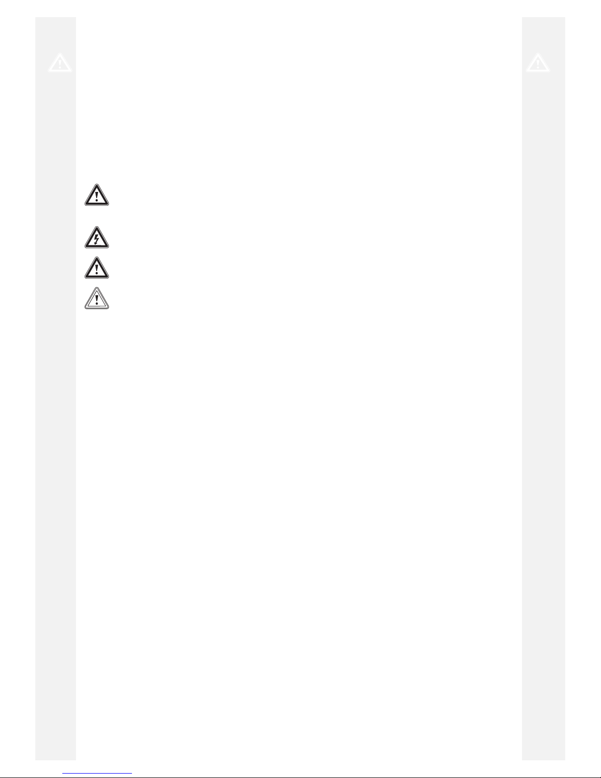
3.3 Control elements
1
9
8
7
6
5
2
3
4
1 Display 2 i button
Page 6

3 Product description
6 Operating instructions ecoVIT exclusiv 0020258609_00
3 Control (accessory)
4 Main switch
5 + button
6 − button
7 Reset button
8 Heating flow temperat-
ure rotary knob
9 Cylinder temperature
rotary knob
The display shows the current heating flow temperature, the
filling pressure of the heating installation, the operating mode
or certain additional information.
The i button is used to call up status information.
The control, which is available as an accessory, automatically controls the flow temperature depending on the outdoor
temperature.
The main switch is used to switch the product on and off.
The + button is used to display the cylinder temperature (if
the product is equipped with a cylinder temperature sensor).
The − button is used to display the filling pressure of the
heating installation.
The Reset button is used to reset the product in the case of
certain faults.
The heating flow temperature rotary knob is used to set the
heating flow temperature if no control is connected. If a control is connected, the heating flow temperature rotary knob
should be turned clockwise as far as it will go.
The cylinder temperature rotary knob is used to set the cylinder temperature if a domestic hot water cylinder is connected.
If a control is connected, the rotary knob should be turned
clockwise as far as it will go. The control then determines the
cylinder temperature.
3.3.1 Digital Information and Analysis System
(DIA)
1
2
1 Display showing the
current heating flow
temperature, the filling
pressure in the heating
installation, or a status
or fault code
2 Plain text display
3.3.2 Displayed symbols
Symbol Meaning Explanation
Fault in the air/flue gas
route
Fault in the air/flue gas
route
Symbol Meaning Explanation
comDIALOG The heating flow and do-
mestic hot water temperature are specified via
the comDIALOG communications system. The
product works at temperatures other than those
set at the rotary knob.
This operating mode can
only be terminated by:
– comDIALOG
– Changing the tem-
perature at the rotary
knobs by more than
± 5 K
This operating mode
cannot be terminated by:
– Pressing the Reset
button.
– Switching the
product off and on
again
Heating mode – Symbol perman-
ently on: Product is
in heating mode operating mode
– Symbol flashing:
Burner anti-cycling
time is active
Hot water generation – Symbol permanently
visible: Charging
mode for the domestic hot water
cylinder is enabled
by the control and
floor-standing boiler
control system
– Symbol flashes:
Domestic hot water
cylinder is being
heated
Heating pump operating
Solenoid valve is actuated
Gas supply to the burner
is open
Current energy demand Display of the current
burner modulation rate
(bar graph display)
Fault during burner
operation
Burner is switched off
Burner operating correctly
Burner is switched on
Page 7

Operation 4
0020258609_00 ecoVIT exclusiv Operating instructions 7
3.4 Frost protection function
The product is equipped with a frost protection function.
If the heating flow temperature falls below 5 °C when the
main switch is on, the product starts up and heats the circulating water to approx. 30 °C.
Caution.
Risk of material damage due to frost.
The frost protection function cannot guarantee flow through the entire heating installation, which means that parts of the heating
installation may freeze and therefore become
damaged.
▶ During a period of frost, ensure that the
heating installation remains in operation
and that all rooms are sufficiently heated,
even when you are away.
▶ Consult a competent person about this.
3.5 Type designation and serial number
The type designation and the serial number are located on a
sticker below the control panel behind the front flap.
The data plate can only be seen by the competent person.
▶ Open the front flap. (→ Page 5)
▶ Read off the type designation and the serial number from
the sticker.
3.6 CE label
The CE label shows that the products comply with the basic
requirements of the applicable directives as stated on the
identification plate.
The declaration of conformity can be viewed at the manufacturer's site.
4 Operation
4.1 Adjustment and display levels
The product has two adjustment and display levels.
The end user level contains information and setting options
that you require as the end user.
The installer level is reserved for the competent person. It is
protected by a code. Only competent persons may change
any settings in the installer level.
4.2 Starting up the product
4.2.1 Opening the isolator devices
1. Ask the competent person who installed the product to
explain to you where these isolator devices are located
and how to handle them.
2. Open the gas stopcock fully.
3. Check that the heating installation flow and return
service valves are open, if such service valves are
installed.
4. If a domestic hot water cylinder is connected, open the
cold-water isolation valve. To check, you can turn on a
hot water tap and see whether water is escaping there.
4.2.2 Switching on the product
1
2
1 Main switch 2 Display
1. Use the main switch (1) to switch on the product.
◁ 1: "ON"
◁ When the main switch is in position 1, the product is
switched on and the standard display for the Digital
Information and Analysis System is shown in the
display. The function menu is immediately shown
in the display once the product has been switched
on. The function menu enables competent persons
to control how the individual actuators work. The
product returns to normal operating mode after a
waiting period of approximately five seconds or if the
− button is pressed.
2. Set up your product according to your needs.
Page 8

4 Operation
8 Operating instructions ecoVIT exclusiv 0020258609_00
4.2.3 Switching off the product
1
2
1 Main switch 2 Display
▶ Use the main switch (1) to switch off the product.
◁ 0: "OFF"
Note
In order for the protection modes, such as
frost protection, to remain activated, only activate and deactivate the product using the
control (you can find information about this in
the relevant operating instructions). If no control is present, block the heating and cylinder
charging mode by turning the dial to the anticlockwise end stop.
4.3 Setting the language
▶ Contact your competent person so that they can set the
correct language for the control panel.
4.4 Setting the heating flow temperature
Conditions: Control connected
2
1
1 Main switch 2 Heating flow temperat-
ure rotary knob
▶ Turn the rotary knob for the heating flow temperature (2)
as far as it will go clockwise.
◁ The heating flow temperature is automatically set by
the control.
Note
To ensure that the control can set temperatures up to the maximum heating flow
temperature, the rotary knob for the heating
flow temperature should always be set to the
clockwise end stop.
Conditions: No control connected
2
1
1 Heating flow temperat-
ure rotary knob
2 Displaying the current
heating flow temperature
▶ Set the target flow temperature on the rotary knob for
the heating flow temperature (1) in accordance with the
outdoor temperature.
Position Meaning
Outdoor temperature
Fully left Frost protection
Anti-clockwise (but
not at the end stop)
Transition Time
Approx.
10 … 20 ℃
Centre Moderate cold
Approx.
0 … 10 ℃
Clockwise Extreme cold
Below
0 ℃
◁ After turning the rotary knob for the heating flow tem-
perature, the display shows the set target flow temperature (2). After three seconds, this display goes
out and the default display reappears (current heating flow temperature).
Note
The maximum heating flow temperature is set
in the factory at 75 °C. This can be defined by
the competent person to be between 40 °C
and 85 °C.
Page 9

Operation 4
0020258609_00 ecoVIT exclusiv Operating instructions 9
4.5 Setting the cylinder temperature
Conditions: Control connected
1
2
1 Display 2 Cylinder temperature
rotary knob
▶ Set the rotary knob for the cylinder temperature (2) as
far as it will go clockwise so that the control can work
without any faults occurring.
▶ Do not set the required cylinder temperature on the
rotary knob for the cylinder temperature; set the cylinder
temperature on the control instead.
Conditions: No control connected
1
2
1 Display 2 Cylinder temperature
rotary knob
▶ Set the rotary knob for the cylinder temperature (2) to
the required cylinder temperature.
Position of the rotary knob for setting the cylinder tem-
perature (→ Page 9)
◁ The required temperature is shown in the display
(1). After three seconds, this display goes out and
the default display reappears (current heating flow
temperature).
Note
The maximum cylinder temperature is set in
the factory at 65 °C. This can be defined by
the competent person to be between 50 °C
and 70 °C.
Note
If a cylinder temperature lower than 60 °C is
required, we recommend that you regularly
use the anti-legionella function via the control.
Position Meaning Temperature
Fully left Minimum cylinder
temperature = frost
protection
15 ℃
Centre Medium cylinder
temperature
≈ 50 ℃
Fully right Maximum cylinder
temperature
65 ℃
4.6 Switching off the functions
4.6.1 Switching off heating mode
Note
You can completely switch off heating mode in
summer without switching off the hot water generation.
1
1 Rotary knob for setting
the heating flow temperature
▶ To switch off heating mode, turn the rotary knob for set-
ting the heating flow temperature (1) as far as it will go
anti-clockwise. If the product is controlled by a control,
use this control to switch off heating mode and leave the
rotary knob at the clockwise end stop.
Note
The product's internal frost protection is therefore guaranteed whether there is a control or
not.
4.6.2 Switching off cylinder charging mode
(using the VRC 630/VRS 620 control)
1. Leave the rotary knob for the cylinder temperature at
the clockwise end stop.
2. Switch the cylinder circuit to "OFF" on the control.
Note
If the VRC 450 or VRC 700 control is available, switch cylinder charging mode off in
accordance with the section "Switching off
cylinder charging mode (without a control)
(→ Page 10)".
Page 10

5 Care and maintenance
10 Operating instructions ecoVIT exclusiv 0020258609_00
4.6.3 Switching off cylinder charging mode
(without control)
▶ Turn the rotary knob for the cylinder temperature to the
anti-clockwise end stop.
◁ Cylinder charging mode is switched off.
◁ The frost protection function is activated for the do-
mestic hot water cylinder.
◁ The display shows the target cylinder temperature of
15 °C for three seconds.
– 15 ℃
Note
The effect of the frost protection function is
that, at cylinder temperatures below 10 °C, the
domestic hot water generation is switched on
until the water in the cylinder has reached 15
°C again.
4.7 Status code meanings
The status codes that are shown in the DIA system's display
provide information about the product's current operating
status.
If several operating statuses occur at the same time, the
applicable status codes are displayed alternately, one after
the other. The status code is explained a plain text display in
the display.
Status codes (→ Page 14)
5 Care and maintenance
5.1 Caring for the product
Caution.
Risk of material damage caused by un-
suitable cleaning agents.
▶ Do not use sprays, scouring agents, de-
tergents, solvents or cleaning agents that
contain chlorine.
▶ Clean the casing with a damp cloth and a little solvent-
free soap.
5.2 Maintenance
An annual inspection and biennial maintenance of the
product carried out by a competent person is a prerequisite
for ensuring that the product is permanently ready and safe
for operation, reliable, and has a long working life. The
inspection may require maintenance to be carried out earlier,
depending on the results.
5.3 Guaranteeing the correct filling pressure of
the heating installation
5.3.1 Checking the system pressure
1
1 − button
▶ Check the heating installation's filling pressure at regular
intervals. Briefly press the − button.
◁ The display will show the filling pressure for approx-
imately 5 seconds.
◁ The filling pressure must be between 0.1 MPa and
0.2 MPa (1.0 and 2.0 bar) when the heating installation is cold in order for the heating installation to operate properly. If the pressure is lower, you must add
heating water before starting up.
Note
You can permanently switch between the temperature or pressure display in the display by
pressing and holding the – button for approximately five seconds.
Note
To avoid operating the heating installation with
an insufficient water volume and to prevent
potential subsequent damage, the product
is fitted with a pressure sensor. The pressure sensor signals the low pressure level if
the level falls below 0.06 MPa (0.6 bar). This
is signalled by the system pressure value in
the display flashing. If the level falls below
0.03 MPa (0.3 bar), the system displays the
fault message and F.22 alternately, and the
burner is blocked. If the system pressure is
lower than 0.06 MPa (0.6 bar), fill the heating installation up again as quickly as possible. As soon as the system pressure exceeds 0.06 MPa (0.6 bar), the product starts
up without any further measures being required.
If the pressure sensor is defective, the
product enters comfort protection mode. The
maximum possible flow temperature and the
power are limited. The status S.40 and F.22
(water deficiency) are displayed alternately.
Note
If the heating installation extends over several
floors, a higher system pressure for the heating installation may be necessary. Ask your
competent person for details.
Page 11
Care and maintenance 5
0020258609_00 ecoVIT exclusiv Operating instructions 11
5.3.2 Filling the heating installation
Caution.
Risk of material damage due to heating
water that is extremely calciferous or corrosive or contaminated by chemicals.
Unsuitable tap water damages the seals
and diaphragms, blocks components in the
product and heating installation through
which the water flows and causes noise.
▶ Only fill the heating installation with suit-
able heating water.
▶ In case of doubt, ask a competent person
for details.
1. Ask a competent person where the filling cock is located.
2. Connect the filling cock to a hot water supply in the way
you were told by the competent person.
3. Open all radiator valves (thermostatic radiator valves) of
the heating installation.
4. Open the hot water supply.
5. Slowly open the filling cock.
6. Fill it with water until the required filling pressure is
reached.
7. Close the hot water supply.
8. Purge all radiators.
9. Then check the filling pressure on the display.
10. Top up with more water if necessary.
11. Close the filling cock.
5.4 Checking the condensate discharge pipe
and tundish
The condensate discharge pipe and tundish must always be
penetrable.
▶ Regularly check the condensate discharge pipe and tun-
dish for faults and, particularly, for blockages.
You must not be able to see or feel any obstructions in the
condensate discharge pipe and tundish.
▶ If you notice a fault, have it eliminated by a competent
person.
5.5 Carrying out the flue gas analysis
Note
Measurement and inspection work must only be
carried out by the chimney sweep or competent
person.
2
1
1 + button 2 − button
1. Switch on the chimney sweep function by pressing the
− and + buttons for the DIA system at the same time.
◁ Shown in the display: S.Fh = Heating chimney
sweep mode; S.Fb = Domestic hot water chimney
sweep mode
◁ The product now works at maximum load for 15
minutes. If you do not press any buttons for 15
minutes or if a flow temperature of 85 °C is reached,
the chimney sweep function is automatically
switched off.
2. Take the measurements at the earliest after three
minutes of the product operating.
Applicability: VKK 226/4, VKK 286/4, VKK 366/4
▶ Remove the upper casing (→ Installation instructions).
▶ Use the test points that are underneath for the meas-
urement (→ Installation instructions).
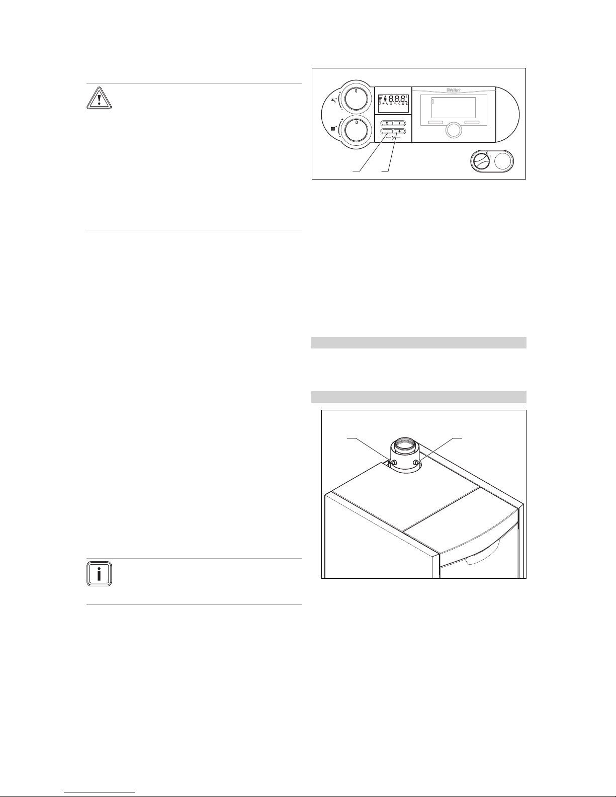
Applicability: VKK 476/4, VKK 656/4
12
1 Flue gas test point 2 Fresh air test point
▶ Use the test points on the adapter for the measure-
ment, as shown.
3. Unscrew the sealing cap from the flue gas test point (1).
4. Remove the sealing cap from the combustion air test
opening (2).
5. Take the measurements in the flue gas route at the flue
gas test point.
Page 12

6 Troubleshooting
12 Operating instructions ecoVIT exclusiv 0020258609_00
– Immersion depth: ≈ 80 mm
6. Take measurements in the air route on the combustion
air test opening (2).
– Immersion depth: ≈ 10 mm
7. Switch off the chimney sweep function by pressing the
− and + buttons for the DIA system at the same time.
8. Screw the sealing cap onto the flue gas test point (1).
9. Fit the sealing cap onto the combustion air test opening
(2).
Applicability: VKK 226/4, VKK 286/4, VKK 366/4
▶ Install the upper casing (→ Installation instructions).
6 Troubleshooting
6.1 Eliminating faults
▶ Use the table in the appendix to attempt to eliminate
faults.
Troubleshooting (→ Page 14)
▶
Press (max. three times) to restart the product.
▶ If you are unable to eliminate the fault and the fault re-
curs despite reset attempts, contact an approved heating
specialist company.
6.2 Checking the product status
Heizbetrieb - Bren
1
2
1 Display 2 i button
1. Call up the product status by pressing the i button.
2. Switch the display back to normal operating mode by
pressing thei button.
7 Decommissioning
7.1 Temporarily decommissioning the product
Caution.
Risk of material damage due to frost
The frost protection and monitoring devices
are only active while the unit is connected to
the power mains, the product is switched on
via the main switch and the gas stopcock is
open.
▶ You must use the control if you want to
activate and deactivate the product in
normal mode.
▶ If no control is present when a main switch
has been switched on, set the rotary
knobs for the target heating flow and
cylinder values to the anti-clockwise end
stop.
▶ Do not disconnect the product from the
power mains when it is in normal mode.
▶ Leave the main switch in position 1 in
normal mode.
1
3
2
1 Main switch
2 Heating flow temperat-
ure rotary knob
3 Cylinder temperature
rotary knob
1. Turn the rotary knob for the cylinder temperature (3)
anti-clockwise as far as it will go.
2. Turn the rotary knob for the heating flow temperature
(2) anti-clockwise as far as it will go.
3. If the fan continues to run, wait until it stops.
◁ "Fan overrun" is shown in the display.
4. Turn the main switch (1) to position 0.
5. Close the gas stopcock and the cold-water isolation
valve.
Note
The isolators are not included in the scope of
delivery for your product. They are installed
on-site by the competent person. Ask the
competent person to explain where the isolators are located and how they are operated.
7.1.1 Draining the heating installation
Another way to protect the heating installation and the
product from frost for very long switch-off periods is to drain
them completely.
▶ Consult a competent person about this.
Page 13

Recycling and disposal 8
0020258609_00 ecoVIT exclusiv Operating instructions 13
7.2 Permanently decommissioning the product
▶ Have a competent person permanently decommission
the product.
8 Recycling and disposal
▶ The competent person who installed your product is re-
sponsible for the disposal of the packaging.
If the product is identified with this symbol:
▶ In this case, do not dispose of the product with the
household waste.
▶ Instead, hand in the product to a collection centre for old
electrical or electronic appliances.
If the product contains batteries that are marked with
this symbol, these batteries may contain substances that are
hazardous to human health and the environment.
▶ In this case, dispose of the batteries at a collection point
for batteries.
9 Guarantee and customer service
9.1 Guarantee
You can request information on the manufacturer's guarantee from the contact address provided on the back page of
this document.
9.2 Customer service
The contact details for our customer service are provided on
the back page or on our website.
Page 14

Appendix
14 Operating instructions ecoVIT exclusiv 0020258609_00
Appendix
A Status codes
Note
Since the code table is used for various products, some codes may not be visible for the product in question.
Statuscode Meaning
S.00 Heating: No heat demand
Heating has no heat demand. The burner is off.
S.01 Heating mode: Fan start-upThe fan start-up for heating mode is activated.
S.02 Heating mode: Pump
pre-run
The pump prerun for heating mode is activated.
S.03 Heating mode: Ignition The ignition for heating mode is activated.
S.04 Heating mode: BurneronThe burner for heating mode is activated.
S.06 Heating mode: Fan overrun
The fan overrun for heating mode is activated.
S.07 Heating mode: Pump
overrun
The pump overrun for heating mode is activated.
S.08 Heating mode: Anti-cycling time
The anti-cycling time for heating mode is activated.
S.20 DHW demand The domestic hot water demand is activated.
S.22 DHW mode: Pump prerun
The pump prerun for domestic hot water mode is activated.
S.24 DHW mode: Burner on The burner for domestic hot water mode is activated.
S.27 DHW mode: Pump overrun
The pump overrun for domestic hot water mode is activated.
S.31 No heat demand: Summer mode
Summer mode is activated; there is no heat demand. The external control blocks heating mode.
S.34 Heating mode: Frost protection
The frost protection function for heating mode is activated.
B Troubleshooting
Symptom Possible cause Measure
No hot water, heating stays cold No gas 1. Check whether the gas stopcock in the building and the gas
stopcock on the product are open.
2. Open one or both of the gas stopcocks.
Installation isolator is closed 1. Check whether one of the isolators is closed.
2. Ask a competent person whether closed isolators can be
opened again.
No power supply 1. Check whether the power supply to the building and the main
switch on the product are switched on.
2. Switch on the power supply to the building and the main
switch on the product.
The display shows S.39 "Contact thermostat activated" (e.g.
by the condensate pump or the
surface-mounted thermostat in
the underfloor circuit)
1. Clean the condensate pump with clean water in accordance
with the operating instructions for the condensate pump or
contact your approved heating specialist company.
2. Contact an approved heating specialist company.
Filling pressure in the heating
installation too low. F.22"Water
pressure too low" appears in
the display
1. Fill the heating installation. (→ Page 11)
2. If the pressure drops too frequently, contact an approved
heating specialist company. The cause of the loss in heating
water must be established and eliminated.
Page 15

Appendix
0020258609_00 ecoVIT exclusiv Operating instructions 15
Symptom Possible cause Measure
No hot water, heating stays cold Fault during the ignition pro-
cess. F.28 "No ignition during
start-up" or F.29 "Flame goes
out during operation" appears
in the display. The symbol is
shown in the display.
1. Check whether the gas stopcock is open.
2. If the gas stopcock is closed, open the gas stopcock with the
agreement of an installation company.
3. Press and hold the reset button for one second to cancel
ignition switch-off after three unsuccessful attempts if the
burner has so far failed to ignite.
4. If the product does not start up after three reset attempts,
contact an approved heating specialist company.
Fault in the air/flue gas route
or condensate discharge. F.32
"Speed deviation too great" or
F.50 "Failure Siphon switch"
appears in the display. The
and symbols are shown in the
display.
1. Contact an approved heating specialist company.
Domestic hot water functioning
correctly; heating does not start
up
Control settings not correct 1. Compare the control settings with the specifications in the
control's operating instructions.
2. Correct the settings in accordance with the operating instructions for the control.
3. Contact an approved heating specialist company if you encounter problems when configuring the settings.
The rotary knob for the heating
flow temperature is not at the
clockwise end stop when the
control is connected
1. Check the setting of the rotary knob for the heating flow temperature when the control is connected.
2. Turn the rotary knob for the heating flow temperature as far
as it will go clockwise.
Heating flow temperature set
incorrectly with no control connected
1. Check the heating flow temperature setting.
2. Set the rotary knob for the heating flow temperature to the
required heating flow temperature with no control connected.
No hot water, heating functioning correctly
Control settings not correct 1. Compare the control settings with the specifications in the
control's operating instructions; the rotary knob for the cylinder temperature is at the clockwise end stop when the control is connected.
2. Correct the settings in accordance with the operating instructions for the control.
3. Contact an approved heating specialist company if you encounter problems when configuring the settings.
The rotary knob for the cylinder
temperature is not at the clockwise end stop when the control
is connected
1. Check the setting for the rotary knob for the cylinder temperature when the control is connected.
2. Set the rotary knob for the cylinder temperature as far as it
will go clockwise when the control is connected.
The cylinder temperature is
set incorrectly with no control
connected
1. Check the cylinder temperature setting.
2. Set the rotary knob for the cylinder temperature to the required cylinder temperature with no control connected.
Page 16

0020258609_00 24.05.2017
Supplier
Vaillant Deutschland GmbH & Co.KG
Berghauser Str. 40 D-42859 Remscheid
Telefon 021 91 18‑0 Telefax 021 91 18‑2810
Auftragsannahme Vaillant Kundendienst 021 91 5767901
info@vaillant.de www.vaillant.de
© These instructions, or parts thereof, are protected by copyright and may be reproduced or distributed only with
the manufacturer's written consent.
We reserve the right to make technical changes.
0020258609_00
 Loading...