

Vaillant electronicVED E ../7 INT II Series, VED E 18/7 INT II, VED E 21/7 INT II, VED E 24/7 INT II, VED E 27/7 INT II Installation Instructions Manual
Installation instructions
electronicVED
VED E ../7 INT II
EXP (ar)
Publisher/manufacturer
Vaillant GmbH
Berghauser Str. 40 D-42859 Remscheid
Tel. +49 21 91 18‑0 Fax +49 21 91 18‑2810
info@vaillant.de www.vaillant.de

Contents
2 Installation instructions electronicVED 0020264435_00
Contents
1 Safety .................................................................... 3
1.1 Action-related warnings ......................................... 3
1.2 Intended use.......................................................... 3
1.3 General safety information .................................... 3
1.4 Regulations (directives, laws, standards).............. 4
2 Notes on the documentation .............................. 5
2.1 Observing other applicable documents ................. 5
2.2 Storing documents................................................. 5
2.3 Validity of the instructions...................................... 5
3 Product description............................................. 5
3.1 Overview................................................................ 5
3.2 Function................................................................. 5
3.3 Information on the data plate................................. 5
3.4 CE label ................................................................. 5
4 Set-up.................................................................... 6
4.1 Checking the scope of delivery.............................. 6
4.2 Selecting an installation location ........................... 6
4.3 Installation clearances ........................................... 6
4.4 Installing the product on the wall ........................... 6
5 Installation............................................................ 8
5.1 Connecting the hot and cold water ........................ 8
5.2 Connecting the product to the electricity supply .... 9
6 Start-up ............................................................... 10
6.1 Removing air pockets from the product............... 10
6.2 Fitting the product casing..................................... 10
6.3 Checking the system's functionality..................... 11
6.4 Activating the scald protection function ............... 11
7 Handing over to the operator ........................... 11
8 Recycling and disposal..................................... 11
9 Troubleshooting ................................................ 11
9.1 Detecting and rectifying faults ............................. 11
9.2 Procuring spare parts .......................................... 12
10 Inspection and maintenance ............................ 12
11 Decommissioning.............................................. 12
11.1 Temporarily decommissioning the product.......... 12
11.2 Permanently decommissioning the product......... 12
12 Customer service............................................... 12
13 Technical data.................................................... 13
Safety 1
0020264435_00 electronicVED Installation instructions 3
1 Safety
1.1 Action-related warnings
Classification of action-related warnings
The action-related warnings are classified in
accordance with the severity of the possible
danger using the following warning signs and
signal words:
Warning symbols and signal words
Danger!
Imminent danger to life or risk of
severe personal injury
Danger!
Risk of death from electric shock
Warning.
Risk of minor personal injury
Caution.
Risk of material or environmental
damage
1.2 Intended use
There is a risk of injury or death to the user or
others, or of damage to the product and other
property in the event of improper use or use
for which it is not intended.
Vaillant electronicVED electric instantaneous water heaters must only be used to heat
up drinking water.
Vaillant electronicVED electric instantaneous water heaters are suitable for use only
in an enclosed, frost-free room in a domestic
environment.
Vaillant electronicVED electric instantaneous water heaters are not suitable for operation in secondary circulation lines.
Intended use includes the following:
– observance of accompanying operating,
installation and servicing instructions for
the product and any other system components
– installing and fitting the product in accord-
ance with the product and system approval
– compliance with all inspection and main-
tenance conditions listed in the instructions.
Intended use also covers installation in accordance with the IP code.
Any other use that is not specified in these
instructions, or use beyond that specified in
this document shall be considered improper
use. Any direct commercial or industrial use
is also deemed to be improper.
Caution.
Improper use of any kind is prohibited.
1.3 General safety information
1.3.1 Risk caused by inadequate
qualifications
The following work must only be carried out
by competent persons who are sufficiently
qualified to do so:
– Set-up
– Dismantling
– Installation
– Start-up
– Inspection and maintenance
– Repair
– Decommissioning
▶ Observe all instructions that are included
with the product.
▶ Proceed in accordance with current tech-
nology.
▶ Observe all applicable directives, stand-
ards, laws and other regulations.
1.3.2 Risk of material damage caused by
frost
▶ Do not install the product in rooms prone
to frost.
1.3.3 Risk of death from electric shock
There is a risk of death from electric shock if
you touch live components.
Before commencing work on the product:
▶ Disconnect the product from the power
supply by switching off all power supplies
at all poles (electrical partition with a contact gap of at least 3 mm, e.g. fuse or circuit breaker).
▶ Secure against being switched back on
again.
▶ Check that there is no voltage.

1 Safety
4 Installation instructions electronicVED 0020264435_00
1.3.4 Risk of death from electric shock
from live lines and connections
The drinking water that is used must demonstrate a specific resistance of ≥ 900 Ω at
15 °C. Otherwise, the product must not be
used.
▶ Before installing the unit, ask your water
company to inform you about the water
resistance and conductivity.
1.3.5 Risk of being scalded by hot water
The outlet temperatures at the draw-off points
can be up to approx. 60 °C.
▶ When using the product, ensure that you
do not scald yourself.
▶ If you want to be protected from scald-
ing, set the maximum temperature of the
product to 43 °C.
1.3.6 Risk of being scalded by hot water
If a solar thermal energy system is connected
upstream, hot water temperatures of over
43 °C could be generated even if the scald
protection function is set.
If a solar thermal energy system is connected
upstream of the product, the inlet temperature must be limited by including precautionary features in the design (e.g. a mixer valve).
▶ Install a mixer valve to limit the inlet tem-
perature to 25 °C.
1.3.7 Risk of being burned or scalded by
hot components
▶ Only carry out work on these components
once they have cooled down.
1.3.8 Risk of material damage caused by
using an unsuitable tool
▶ Use the correct tool to tighten or loosen
threaded connections.
1.4 Regulations (directives, laws,
standards)
▶ Observe the national regulations, stand-
ards, guidelines and laws.
Notes on the documentation 2
0020264435_00 electronicVED Installation instructions 5
2 Notes on the documentation
2.1 Observing other applicable documents
▶ You must observe all the operating and installation in-
structions included with the system components.
2.2 Storing documents
▶ Pass these instructions and all other applicable docu-
ments on to the system operator.
2.3 Validity of the instructions
These instructions apply only to:
Product article number
VED E 18/7 INT II
0010023714
VED E 21/7 INT II
0010023715
VED E 24/7 INT II
0010023716
VED E 27/7 INT II
0010023717
3 Product description
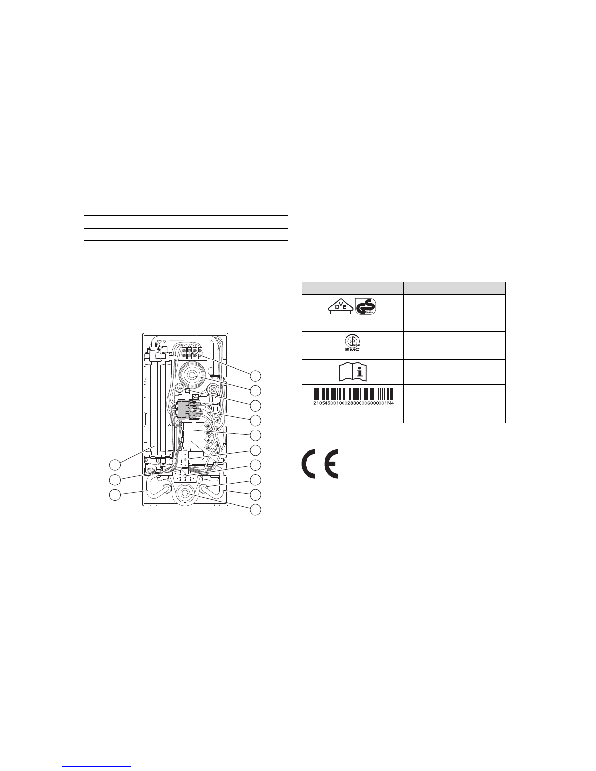
3.1 Overview
10
9
11
12
13
8
7
6
5
4
3
2
1
1 Mains connection ter-
minal
2 Top cable duct
3 Adjustment spindle
4 Safety switch
5 Electronics
6 Temperature selector
(infinitely variable)
7 Optional space under-
neath for the mains
connection terminal
8 Filter
9 Cold water connection
10 Bottom cable duct
11 Hot water connection
12 Safety overheat cut-off
device
13 Heating block
3.2 Function
The product heats up drinking water via a bare wire in the
heating block using the flow-through principle.
The drinking water can be drawn from several draw-off
points.
The electronics measure the temperature of the water in the
cold water supply and the water volume flow. The electrical
performance that is required to heat the water to the required
hot water temperature is calculated using these two values.
The temperature can be set to any value between 30 °C and
60 °C on the product's temperature selector.
The hot water temperature depends on:
– Water inlet temperature
– Water outlet volume
– Performance category of the unit
If the set hot water temperature is not reached, reduce the
water volume.
3.3 Information on the data plate
Symbol Meaning
The VDE GS mark confirms
that the unit complies with
standards and has been
tested for safety.
Symbol confirming conformity
with the electromagnetic compatibility standard
Read all of the instructions.
Barcode with serial number,
The 7th to 16th digits of the
serial number form the article
number
3.4 CE label
The CE label shows that the products comply with the basic
requirements of the applicable directives as stated on the
identification plate.
The declaration of conformity can be viewed at the manufacturer's site.

4 Set-up
6 Installation instructions electronicVED 0020264435_00
4 Set-up
4.1 Checking the scope of delivery
▶ Check that the scope of delivery is complete.
Quantity Description
1
electronicVED electric instantaneous water
heater
1
Operating instructions and installation instructions
1
Bag containing fixing material (2 bolts, 2 rawl
plugs, 3 seals, 1 special fixing screw)
1 R 1/2 cold water connection piece with a
cold water stop valve
1 R 1/2 hot water connection piece
2 Double nipple
1 Installation plate
1 Installation template
4.2 Selecting an installation location
▶ Install the product as close as possible to the draw-off
points that are used most frequently.
Note
The product may also be installed above baths
or in a shower area.
4.3 Installation clearances
_
+
D
C
E
A
C
B
B
A At least 50 mm
B At least 50 mm
C At least 120 mm
D At least 130 mm
E Maximum 22 mm
The bottom section of the product (D) must be level with the
product's bearing area on the wall;.
4.4 Installing the product on the wall
4.4.1 Product and connection dimensions
_
+
240
100
7050
277
481
322
5
16
19
100
7
35 35
1
2
3
4
5
6
1 Top cable duct
2 Central attachment
3 Temperature selector
4 R 1/2 hot water connec-
tion
5 R 1/2 cold water con-
nection
6 Bottom cable duct
7 R 1/2 outside thread
390
277
8585
1
23
1
1 Installation plate
2 Cold water connection
3 Hot water connection

Set-up 4
0020264435_00 electronicVED Installation instructions 7
4.4.2 Removing the product casing
X9
4
2
3 51
1. Grip the two straps (1) on the panel (2).
2. Splay the two straps (pull them away from the product).
3. Remove the panel (2).
4. Undo the two screws (3).
5. Fold up the cover (4).
6. Pull the temperature selector plug from the electronics
(slot X9) in the product (5).
7. Remove the cover (4) from the product.
4.4.3 Installing the product
390
277
8585
1
2
2
1
1. Hold the installation template against the wall and mark
the fixing points.
– Product alignment: Vertically on the wall
Note
When replacing a product, you can use the
drill holes from the previous installation
provided these are compatible with the
additional holes in the installation plate.
2. Use rawl plugs and screws to secure the installation
plate (1) to the fixing points (2).
Danger!
Risk of electric shock caused by penetrat-
ing water
The cable duct prevents water from penetrating along the mains connection cable
and into the product. If the cable duct is completely cut away, water can very easily penetrate and damage the product and may cause
a potentially lethal electric shock.
▶ Never cut off the cable duct completely.
▶ Cut the end of the cable duct in such a
way that the sleeve tightly surrounds the
mains connection cable.
3. Fold the cable duct up or down depending on the location of the mains connection cable.
4. Feed the cable through the cable duct and into the product's interior.

5 Installation
8 Installation instructions electronicVED 0020264435_00
1
2
4
3
5. Fit the product (2) to the retaining screw (1) on the installation plate.
6. Use the adjustment spindle (4) to adjust the product.
7. Use the fixing screw (3) to secure the product.
5 Installation
▶ Flush the cold water pipes thoroughly before installation.
5.1 Connecting the hot and cold water
Caution.
Possible damage caused by unsuitable
plastic pipes.
Damage may be caused by unsuitable plastic
pipes.
▶ Use only plastic pipes that are permitted
for normal operation at 65 °C.
▶ Use only plastic pipes that can withstand
at least one hour at a maximum temperature of 95 °C and a maximum pressure of
1 MPa (10 bar) (check the manufacturer's
specifications).
▶ When using plastic pipes, ensure that they
conform with DIN 16893 and DIN 16892
(check the manufacturer's specifications).
1. Note the water connections for the installation:
– An expansion relief valve on the cold water pipe is
not required.
– All cold and hot water pipes can be made of steel,
copper or plastic.
1
2. To simplify installing the water connection, the bottom
section of product frame can be folded up (1).
– Do not remove the folding frame.
1
2
3
4
7
6
3
5
Caution.
Risk of damage caused by leaks.
Mechanical tension on supply lines may
cause leaks and damage to the product.
▶ Avoid mechanical tension on supply lines.
3. Put hemp on the two double nipples (2) and (6) and use
the connections to screw the double nipples to the wall
(1) and (7).
4. Insert the seals (3) in the cap nuts of the cold (4) and
hot water connections (5).
5. Screw the cold water connection piece (4) to the cold
water connection double nipple (2) in the wall (1).
6. Screw the hot water connection piece (5) to the hot
water connection double nipple (6) in the wall (7).
7. Insert a seal into the cap nut of the unit-side hot water
connection.

Installation 5
0020264435_00 electronicVED Installation instructions 9
Caution.
Risk of damage due to pipes being
blocked by foreign bodies in the water
A water filter that stops foreign bodies entering the product must be fitted to the cold
water flow. The product must not be used
without a water filter. A water filter has been
installed inside the product's cold water pipe
at the factory.
▶ During installation, check that the water
filter is present.
8. After installing the water connection, fold the lower section of the product frame back until it engages.
5.2 Connecting the product to the electricity
supply
1. Note the specifications on the identification plate when
carrying out the electrical installation.
2. Note:
– The product must be installed using a permanent
connection.
– The permanent connection must be equipped with
a customer-supplied partition that has a contact
opening of at least 3 mm on all lines (e.g. via a line
protection switch).
– The product must be connected to the protective
conductor.
– The product is delivered pre-assembled. When car-
rying out the electrical installation, only the electricity
supply line needs to be fed into the product through
one of the two cable ducts and connected.
– The electrical connection must be secured to the up-
per section of the product at the factory. If required,
the connection can be routed in the lower section.
The electrical supply line is then guided through the
lower cable duct.
5.2.1 Carrying out the top electrical connection
4
3
2
1
1. Guide the electrical supply line through the upper cable
duct (2).
2. Connect the individual conductors to L1, L2, and L3 on
the mains connection terminal (1).
3. Connect the protective conductor (4) (3).
5.2.2 Carrying out the bottom electrical
connection
3
2
5
4
6
1
1. Guide the electrical supply line through the lower cable
duct (3).
2. Unscrew the mains connection terminal (1).
3. Route the mains connection terminal (6), including the
internal cable, to the lower position (2) in the product.
4. Screw the mains connection terminal to the lower position (2).
5. Check whether the cables for the mains connection
terminal are routed correctly.
6. Connect the individual conductors to L1, L2, and L3 on
the mains connection terminal (1).
7. Connect the protective conductor (5) (4).

6 Start-up
10 Installation instructions electronicVED 0020264435_00
5.2.3 Installing an optional load-shedding relay
If required, a load-shedding relay that conforms with current
standards can be connected to the product. The role of the
relay is to switch off other power consumers while hot water
is being drawn off via the product so that the house installation is not overloaded. The load-shedding relay must fulfil the
following criteria:
– Pull-in current < 15 A
– Continuous current > 50 A
▶ Install the load-shedding relay in the L2 outer conductor.
▶ If the product is a replacement product, also replace the
load-shedding relay.
6 Start-up
6.1 Removing air pockets from the product
Caution.
Risk of damage from heating wire dry fire
If the air pockets have not been removed
from the product before it is started up, there
is a risk of heating wire dry fire and damage
to the product.
▶ Disconnect all supply lines from the power
supply.
▶ Secure the product against being uninten-
tionally switched back on again.
▶ Check that there is no voltage in the sup-
ply lines and connections.
▶ Check that the product is de-energised.
1. Open the cold water stop valve in the cold water pipe.
2. Open the hot water stop valve for at least one minute.
3. Close and open the hot water draw-off valve several
times.
Note
In normal operating mode, the product will
not need to be purged again.
1
4. Press the safety switch (1).
6.2 Fitting the product casing
X9
2
1
3
4
If the cable for the temperature selector is not plugged into
the electronics, the electronics cannot regulate the power.
The outlet temperature is 30 °C.
▶ Plug the cable (4) for the temperature selector into
slot X9 in the electronics.
▶ Put the product casing (1) on.
▶ Tighten the two screws (3).
▶ Grip the panel (2) using the two straps.
▶ Splay the two straps (slightly pull the panel apart).
▶ Put the panel (2) on.
▶ Close the hot water draw-off valve.
▶ Connect the product to the power mains (switch on the
fuse).

Handing over to the operator 7
0020264435_00 electronicVED Installation instructions 11
6.3 Checking the system's functionality
_
+
1. Connect the product to the power mains (switch on the
fuse).
2. Check the product's power while water is running at a
draw-off point.
3. Turn the temperature selector from hot (left-hand stop =
approx. 30 °C) to hot (right-hand stop = approx. 60 °C).
6.4 Activating the scald protection function
1. Disconnect the product from the power supply.
2. Remove the product casing (→ Page 7).
_
+
3. Turn the temperature selector as far as it will go in an
anti-clockwise direction.
1
4. Move the red lever (1) at the back of the product casing.
◁ This activates the scald protection function and en-
sures that the outlet temperature does not exceed
43 °C.
5. Refit the product casing (→ Page 10).
6. Connect the product to the power mains (switch on the
fuse).
7 Handing over to the operator
1. Provide the operator with all relevant instructions and
unit documentation for safe-keeping.
2. Go through the operating instructions with the operator .
3. Answer any questions they may have.
4. Draw special attention to the safety instructions which
the operator must follow.
5. Inform the operator that there is a risk of scalding when
the hot water temperature exceeds 43 °C.
6. Inform the operator that they must not attempt to repair
the product under any circumstances.
7. Inform the operator that they must not remove the
product casing.
8. Inform the operator of the necessity to ensure that the
system is regularly inspected/maintained and that this
must only be carried out by a competent person (inspection/maintenance contract).
8 Recycling and disposal
Disposing of the packaging
▶ Dispose of the packaging correctly.
▶ Observe all relevant regulations.
9 Troubleshooting
9.1 Detecting and rectifying faults
Fault Possible cause Troubleshooting
Product disconnected from the
power supply
Building's fuse has
been tripped
▶ Replace the electronics system.
The safety switch in
the product has been
triggered
▶ Replace the electronics system.
No hot water; the
water remains
cold
Product is disconnected from the
power supply
▶ Check L1, L2
and L3 against PE
(230 V) and L1, L2
and L3 (400 V).
▶ If there is no
voltage, proceed as
described under
the fault "Product
disconnected from
the power supply".
The measured value
on the heating block
(connection 1
against connection 4) is greater
than 200 Ω
▶ Replace the heating block.
No relay clicking on
the electronics when
the draw-off starts
▶ Replace the impeller.
Other cause ▶ Replace the elec-
tronics system.
The water does
not become hot
enough
The set target temperature or volume
flow are not set correctly
▶ Set the target
temperature to
approx. 40 °C and
the volume flow to
approx. 5 l/min.

10 Inspection and maintenance
12 Installation instructions electronicVED 0020264435_00
Fault Possible cause Troubleshooting
The water does
not become hot
enough
The measured value
on the heating block
(connection 1
against connection 4) is greater
than 200 Ω
▶ Replace the heating block.
The relay only clicks
on the electronics
when there is more
than 4 l/min
▶ Replace the impeller.
Other cause ▶ Replace the elec-
tronics system.
9.2 Procuring spare parts
The original components of the product were also certified
by the manufacturer as part of the declaration of conformity.
If you use other, non-certified or unauthorised parts during
maintenance or repair work, this may void the conformity of
the product and it will therefore no longer comply with the
applicable standards.
We strongly recommend that you use original spare parts
from the manufacturer as this guarantees fault-free and safe
operation of the product. To receive information about the
available original spare parts, contact the contact address
provided on the reverse of these instructions.
▶ If you require spare parts for maintenance or repair
work, use only the spare parts that are permitted for the
product.
10 Inspection and maintenance
▶ Carry out a function check and visual inspection of the
product every three years.
▶ If the water is extremely calciferous, you must de-scale
the product more frequently.
If the water has a large volume of suspended matter, the water filter in the cold water flow must be replaced more frequently. At the same time, the water filter has a sealing function.
Caution.
Risk of damage caused by leaks
After changing the water filter in the cold water flow, leaks may occur due to the new filter
being installed incorrectly.
▶ When installing a new water filter in the
cold water flow, make sure that the filter
is correctly positioned in the pipe and that
the connection is sealed.
▶ Replace the water filter in the cold water flow.
▶ Check for deposits in the hot water pipe between the
heating block and the hot water connection.
▶ When re-assembling the product, insert a new flat seal
into the hot water connection.
▶ Check whether it is necessary to de-scale the product.
▶ De-scale the product as required.
▶ If the product needs to be completely de-scaled, attach a
de-scaling pump between the cold and hot water connection.
▶ After de-scaling the product, flush it thoroughly with wa-
ter.
▶ After de-scaling, remove any air pockets from the product
(→ Page 10).
11 Decommissioning
11.1 Temporarily decommissioning the product
1. Disconnect the product from the power supply.
2. Close the cold water stop valve.
11.2 Permanently decommissioning the product
1. Disconnect the product from the power supply.
2. Close the cold water stop valve.
3. Loosen the cold water and hot water connections.
4. Capture the residual water (up to 0.4 litres) that is left
inside the product using a suitable vessel.
5. Remove the product.
12 Customer service
تجد بيانات الاتصال بخدمة العملاء الخاصة بنا من خلال العنوان
الموضح بأسفل الصفحة الخلفية أو على موقع الإنترنت
www.vaillant.com.

Technical data 13
0020264435_00 electronicVED Installation instructions 13
13 Technical data
Unit E 18/7 INT II E 21/7 INT II E 24/7 INT II E 27/7 INT II
For supplying —
One or more draw-off points
1)
Design — Product for wall-mounting
Equipment — Bare wire heating coil
Capacity l 0.4
Width
Height
Depth
mm
mm
mm
240
481
100
Weight (filled) kg 4.4
Performance characteristics — Electronically regulated output
Water inlet temperature °C 1 ... 25
Minimum start-up flow l/min 3
Switch-off water volume l/min 2.5
Minimum start-up pressure MPa (bar) > 0.015 (> 0.15)
Max. water flow rate l/min 7 9
Rated overpressure MPa (bar) 1 (10)
Rated power kW 18 21 24 27
Minimum water resistance at 15 °C Ω•cm ≥ 900
Measuring voltage — 3/PE ~ 400 V; 50 Hz
Safety — Complies with international safety regulations; radio-shielded;
does not affect the mains supply
IP rating — IP 25 = Sprayed-water protection
1)
Closed product (pressurised)


0020264435_00 22.09.2017
Supplier
Vaillant Group International GmbH
Berghauser Strasse 40 42859 Remscheid
Tel. +49 21 91 18‑0
www.vaillant.info
© These instructions, or parts thereof, are protected by copyright and may be reproduced or distributed only with
the manufacturer's written consent.
We reserve the right to make technical changes.
0020264435_00
 Loading...