

Vaillant recoVAIR/3 SERIES, recoVAIR VAR 275/3, recoVAIR VAR 350/3 Operating And Installation Manual
Page 1
For the owner and expert technician
Operating and Installation Manual
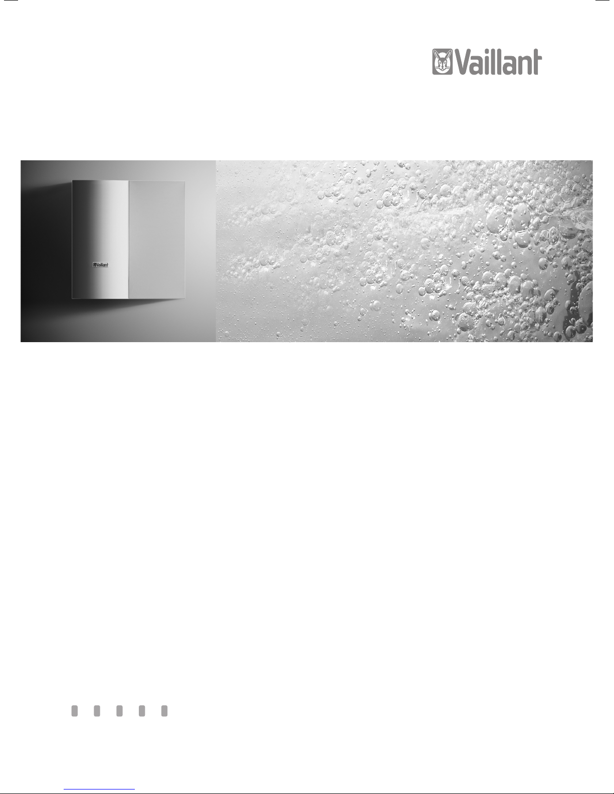
recoVAIR/3
Domestic ventilation unit with heat recovery and remote control
recoVAIR VAR 275/3
recoVAIR VAR 350/3
GB
Page 2

Page 3

For the owner
Operating Manual
recoVAIR/3
Contents
General Information...................................................4
1 Notes on the documentation .........................4
1.1 Documents storage ................................................4
1.2 Used Symbols ...........................................................4
1.3 Manual Validity ........................................................4
1.4 CE Label .....................................................................4
1.5 Identification Plate .................................................5
2 Safety Instructions and Regulations ...........5
2.1 Safety Instructions .................................................5
2.1.1 Assembly and Installation .....................................5
2.1.2 Operation ..................................................................5
2.1.3 Changes in the Environment of the
Domestic Ventilation Unit .....................................5
2.2 Precaution Instructions .........................................6
3 Installation and Operation Instructions ......6
3.1 Intended Use ............................................................6
3.2 Installation Site Requirements ............................6
3.3 Servicing ....................................................................6
3.4 Recycling and Disposal ..........................................6
3.4.1 Device .........................................................................6
3.4.2 Packing ......................................................................6
3.5 Energy Saving Tips ................................................. 7
4 Handling ...........................................................7
4.1 Assembling of the Domestic Ventilation
Unit .............................................................................7
4.2 Bypass (optional) ....................................................7
4.3 Switching-on and -off of the device ................... 7
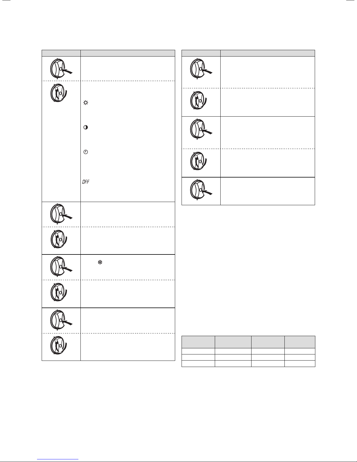
4.4 Functional Overview of the Digital Remote
Control ....................................................................... 7
4.5 Display Overview .....................................................8
4.5.1 Meaning of Symbols ...............................................8
4.6 Settings from the Basic Display ..........................8
4.7 Programming of the Clock Timer .......................9
4.8 Special functions ................................................... 10
4.9 Information Level ....................................................11
5 Troubleshooting ..............................................11
6 Maintenance .................................................. 12
6.1 Cleaning or Replacing the Filter in the
Domestic Ventilation Unit ....................................12
6.2 Cleaning or Replacing the Filters in the
Bypass Casing .........................................................13
6.3 Filter ..........................................................................13
7 Warranty and Customer Service .................13
7.1 Manufacturer’s Warranty and Liability.............13
7.2 Vaillant Service .......................................................13
Page 4

General Information
1 Notes on the documentation
General Information
The domestic ventilation unit consists of a central ventilation appliance for air exchange with heat recovery and
a remote control. For summer operation, you can obtain
a bypass as accessory. It can directly provide living
rooms with cool external air whenever it is necessary.
The external air flow bypasses the heat exchanger.
The unit is connected to an air ducting system, which is
equipped with silencers, pre-filters, fresh-air and exhaust-air grilles and louvres.
Fresh air grilles supply fresh air to the living areas and
stale moist air is extracted from the kitchen, bathroom
and WC.
With the digital remote control the user is able to automatically switch and adapt the domestic ventilation unit
power to their own requirements.
The unit ensures:
– A constant air exchange in the building
– The hygienic minimum air exchange in accordance
with UK building regulations Part F
– Energy savings thanks to high efficiency heat recov-
ery
– A high hygiene standard due to the prevention of hu-
midity and mould damages of the building
The exact model description of the unit is to be found
on the identification plate positioned below the unit.
1 Notes on the documentation
The following notes serve as a guide for the entire documentation.
Other documents are valid in connection with this operating manual.
We accept no liability for any damage caused by failure to observe these instructions.
1.1 Documents storage
Please store this operating manual and other applicable
documents where they are accessible at all times.
1.2 Used Symbols
When operating the unit, please observe the safety instructions in this operating manual!
Danger!
d
Immediate danger to life and limb!
Danger!
e
Risk of death from electric shock!
Caution!
a
Potentially dangerous situation for the product
and environment!
Note
h
Useful Information and Hints.
• Symbol for a required task.
1.3 Manual Validity
This operating manual applies exclusively to units with
the following article numbers:
0010006801
0010006802
For the article number of your unit, refer to the identification plate.
1.4 CE Label
The CE label shows that the recoVAIR ventilation unit
complies with the basic requirements of the following
directives and guidelines:
– Low-voltage Directive 73/23/EEC, modified with
Directive 93/68/EEC
– EMC-Directive 89/336/EEC, modified by the Directive
91/263/EEC, 92/31/EEC and 93/68/EEC
Operating Manual recoVAIR/3 0020062918_034
Page 5
Notes on the documentation 1
Safety instructions and regulations 2
1.5 Identification Plate
Vaillant GmbH Remscheid / Germany
Serial-no. 1234567890xxxxxx
VAR 275 / 3
P
V
dP
T
Max
Max
Max.
210 W
275 m³ / h
170 Pa
Max
60 °C
IPX2
Bar – Code
230V~ 50 HZ
2.1.1 Assembly and Installation
The installation of the device can only be carried out by
a qualified expert technician. He/she will be responsible
for the correct installation and start-up.
He/she is also responsible for the inspection and the
corrective maintenance of the device as well as for the
changes in the air flow adjustment.
If the system is used for ventilation in locations with
room-dependent combustion equipment depending on
the room air, the corresponding flue gas extraction systems must be checked and maintained by a trained
technician. It is mandatory to prevent flue gas leakage
from the combustion equipment.
2.1.2 Operation
Note that the device can only be used if all ventilation
pipes of the device are connected and the entire device
is closed.
The unit must only be operated with the supplied filters
installed. Regularly check whether the filters are dirty
and damaged.
We recommend to visually check the filters every
6 months and to replace them every 12 months, or after
2000 operating hours at the latest. If the system is to
be used for ventilation purposes in locations with roomdependent combustion facilities, the corresponding flue
gas extraction systems must be checked and maintained
by suitably trained personnel.
Fig. 1.1 Identification Plate
The identification plate is positioned below the unit. The
indications given on the identification plate have the following meaning:
Units Value Description
230 V ~50 Hz Mains voltage
P
V
dP
T
Table 1.1 Explanation of identification plate
210 W Maximum electrical power consumption
max
275 m3/h Maximum air volume flow
max
170 Pa Allowable pressure loss of the device at
max
60 °C Maximum operating temperature
Max
V
Max
2 Safety Instructions and Regulations
2.1 Safety Instructions
Always observe the following safety instructions and
regulations.
2.1.3 Changes in the Environment of the Domestic
Ventilation Unit
Caution!
a
Do not make any changes to the unit or casing
which might impair the system functions!
Do not modify
- the unit,
– the outside air, fresh air, exhaust and discharge air
ducts, the pipes for condensation water and the unit
mains connection.
This also applies to alterations to structural elements in
the vicinity of the unit which might affect its operational
safety.
– do not obstruct the air inlets and outlets with doors,
ceilings, windows and walls even temporarily. Do not
cover the air inlets and outlets, e.g. with clothes or
similar. When laying floor materials, do not block or
reduce the vent apertures at the bottom of the doors.
To make alterations to the unit or to its environment,
you must refer to the suitably qualified expert technician who is qualified to do this work.
5Operating Manual recoVAIR/3 0020062918_03
Page 6

2 Safety instructions and regulations
3 Installation and Operation Instructions
Only expert technicians are authorised to execute repair
and maintenance work (with the exception of replacing
the filters). It is recommended that you carry out a visual inspection of the filters at least every 6 months and
replace the filters every 12 months, or at least after
2,000 hours of operation."
2.2 Precaution Instructions
Danger!
e
Risk of fatal electric shock from touching live
connections.
Before working on the unit always disconnect
from the mains supply and ensure that the unit
cannot be restarted.
In case of failures during operation, proceed in accordance with the fault finding table of chapter 5 of this
document. In case it is not possible to eliminate the
fault, please contact an expert technician.
3 Installation and Operation
Instructions
3.1 Intended Use
The Vaillant domestic ventilation units are built and designed according to accepted safety rules and regulations. Nevertheless, improper use can cause serious or
fatal injury to the user or others, and the appliance or
other property can be damaged.
This device is not designed to be used by persons (including children) with limited mental and sensory capabilities or by persons who have not enough experience
and/or knowledge, unless they are supervised by a person who is responsible for their safety or have been instructed by him/her about how to use the device.
Children must be supervised to ensure they do not play
with the unit.
The domestic ventilation unit must be installed by a
qualified technician, who is responsible for the observance of the existing regulations, rules and guidelines.
Due to high level of dust, operation during the construction phase is not allowed.
The domestic ventilation units are specifically designed
for the ventilation of residential spaces. The remote
control including the operating mode selector and the
timer must only be used for controlling the domestic
ventilation unit as described in these instructions; it is
not designed for any other purpose.
Any other or additional use is considered to be improper. The domestic ventilation unit is not suitable for ventilating swimming pools.
The manufacturer/supplier shall not be responsible for
any damages resulting from such improper use.
The user alone bears the risk.
Intended use includes observing the operating and installation manual and all other applicable documents, as
well as adhering to the maintenance and inspection conditions.
Caution!
a
Any improper use is forbidden.
3.2 Installation Site Requirements
– These ventilation units may be internally installed in
flats, cellar spaces, storage or multipurpose rooms as
well as in attic spaces.
– The unit must be mounted wall-hung and in the verti-
cal position. Please observe the permitted load carrying capacity of the wall.
– There must be enough space for mounting the air
duct connections, for a 230V mains voltage connection (usually a switched socket outlet) provided by the
customer as well as a drain outlet with a drain trap.
– The installation site should be frost-proof.
– The installation site must be equipped with a ventila-
tion system.
– The local mains power isolator must always be
easily accessible.
3.3 Servicing
• Clean the cladding of your unit with a damp cloth and
a little soap.
Note
h
Do not use abrasive cleansers or agents which
could damage the cladding of the coated steel
plate.
3.4 Recycling and Disposal
The ventilation unit as well as the packaging consist
mainly of recyclable raw materials.
3.4.1 Device
The filters used with the unit may be disposed of with
the normal household waste. Do not dispose the unit
and the other accessories with normal household waste.
Please ensure that the old unit and accessories are
properly disposed of.
Note
h
Please observe applicable national regulations.
3.4.2 Packing
Leave the disposal of the transport packaging to the
qualified servicing company which installed the appliance.
Operating Manual recoVAIR/3 0020062918_036
Page 7
Installation and Operation Instructions 3
Handling 4
3.5 Energy Saving Tips
Although this unit is used to increase comfort and energy savings, it is possible to maximise energy savings if
you observe the following.
Note
h
At low ambient temperatures below the room
temperature, you will reach the maximum energy saving if you keep the windows closed and
ensure the necessary air exchange by the operation of the domestic ventilation unit.
It goes without saying that venting the room is always
possible by opening the windows.
4 Handling
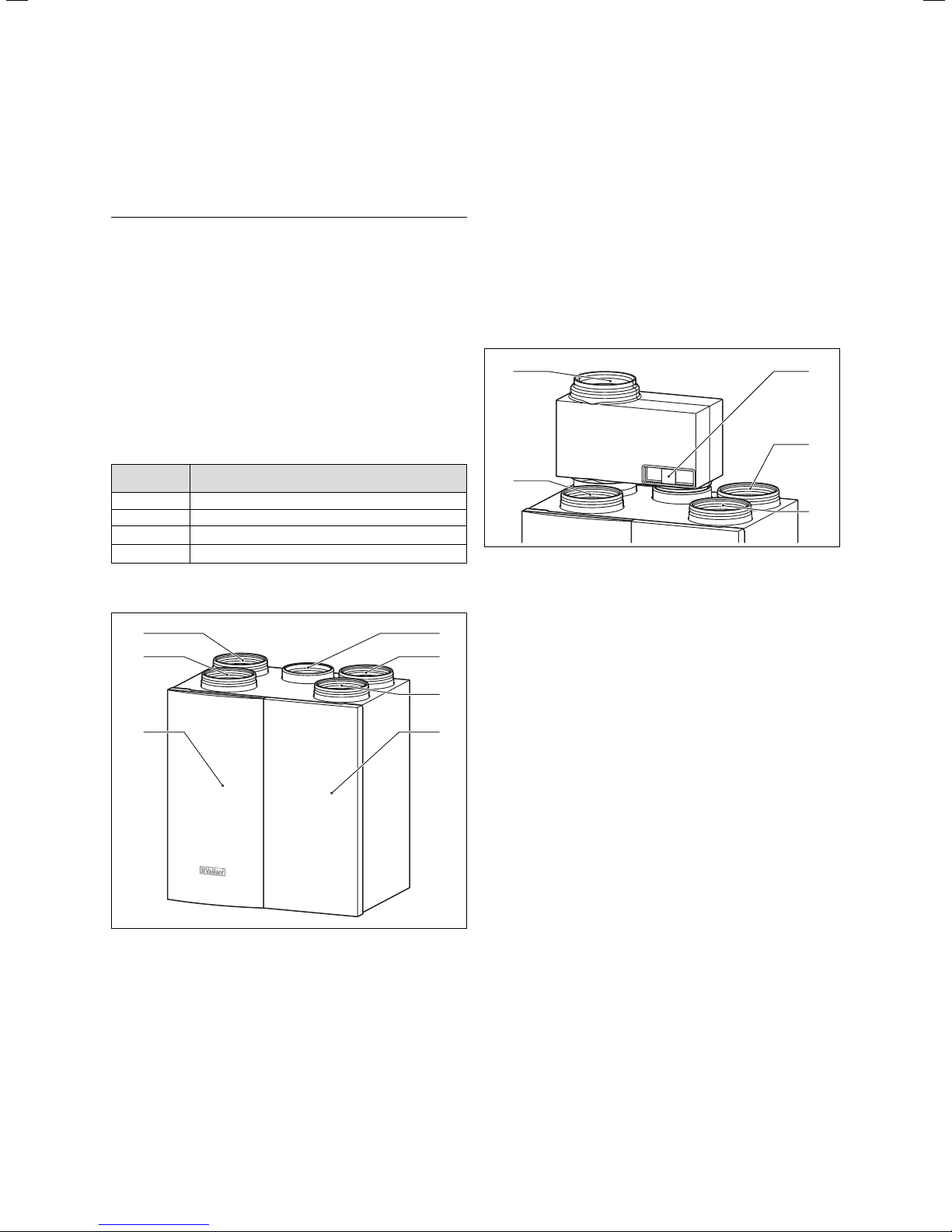
4.1 Assembling of the Domestic Ventilation Unit
Designation Explanation
Fresh air From the ventilation unit into the living space
Exhaust air From the living space into the ventilation unit
Outside air From outside to the domestic ventilation unit
Outgoing air From the domestic ventilation unit to outside
Table 4.1 Designation of the ventilation ducts
7
6
1
2
4.2 Bypass (optional)
The device can be equipped with a bypass, which is fitted on the top of the device, see fig. 4.2.
With a bypass installed the user may operate the socalled "free cooling mode" during the summer months
with the outside temperature falling below room temperature during the night. The cooler outside temperature will not be warmed by the device before it was
blown into the room. To protect the bypass valve from
dirt, we recommend an outside air filter of the filter
class at least G3. The filter is installed on site into the
outside air duct, possibly close to the air inlet.
5
4
Fig. 4.2 Bypass
Key
1 Filter
2 Outgoing air connection
3 Fresh air connection
4 Exhaust air connection
5 Aeration with the outside air
1
2
3
5
Fig. 4.1 recoVAIR VAR 275/3 and 350/3
Key
1 Bypass connection 5 Door in cladding
2 Discharge air duct connec-
tion
3 Fresh air duct connection 7 Outside air duct connec-
4 Front cladding
6 Exhaust air duct connec-
tion
tion
3
4.3 Switching-on and -off of the device
The domestic ventilation unit is supplied with electrical
4
power via a 230 V mains line.
• Insert the mains plug into the 230-V socket.
The electronics of the ventilation appliance is starting.
The display shows the unit type (display "RECO 275 or
350") and then, after about 3 seconds, the indication
switches to the basic display.
• To switch off the unit, pull the mains plug out of the
plug socket. Using the "off" menu point on the remote
control switches the unit to the lowest fan speed.
4.4 Functional Overview of the Digital Remote
Control
The domestic ventilation unit is equipped with a digital
remote control to operate the unit.
The remote control has three buttons as well as a dial
(Vaillant operating concept "turn and click") to set various operating programs. In addition, you can set special
functions as well as a time-controlled function of the
ventilation unit.
7Operating Manual recoVAIR/3 0020062918_03
Page 8
4 Handling
1
2
Fig. 4.3 Digital Remote Control recoVAIR
Key
1 Display
2 Dial ("Turn and Click")
i Information key
F Special functions key
P Programming key (expert technician level)
4.5 Display Overview
The display shows either the current operating mode in
the basic display or, if activated, the special function.
Furthermore, the current room temperature, current
weekday and current time is displayed.
7
1
6
2
5
4.5.1 Meaning of Symbols
The following symbols may appear in the display:
Symbol Meaning
Special function Energy-saving
Special function Advance
Special function Holidays
Static: 2nd fan stage (day mode)
Flashing: 3rd fan stage (HIGH)
Off: 1. fan stage (night mode)
Static: Cooling required
Flashing: Bypass open (summer mode)
Off: Bypass not fitted or closed
Automatic mode
Day mode (2nd fan stage)
Night mode (1st fan stage)
Mode with fan stage holidays (minimum)
Actual room temperature
Day of week
Multi-function display left (time ...)
Multi-function display right (KWh)
Information level
Time programming level
Installer level
Service/diagnostic level
Table 4.2 Symbols
4
Fig. 4.4 Display Overview
Key
1 Operator levels
2 Ventilators/Bypass display
3 Multi-functional display
4 Week days
5 Actual values
6 Operation modes
7 Special functions
4.6 Settings from the Basic Display
3
From the basic display you can select and then change
the major functions with the "turn and click" dial:
With the "click" - you can move from one menu item to
the other. Press the dial from the
basic display several times in a row
until you have reached the desired
function.
The parameter to be changed is
blinking and an indication arrow appears.
With the "turn" - you can change the blinking value.
Note
h
After the necessary settings have been made,
no confirmation is required.
10 seconds after the last input the indicated
function is automatically activated and then
the display returns to the basic display.
Operating Manual recoVAIR/3 0020062918_038
Page 9
Handling 4
Action Setting of
Operating mode
Selected symbol is flashing
Click
Turn the dial in order to change the operat-
Turn
ing mode.
You can select the following settings:
Day mode:
Irrespective of the time programme the
remote control switches the fans into
2nd stage.
Night mode:
Irrespective of the time programme the
remote control switches the fans into
1st stage
Automatic operation:
The change between the day and night
operation occurs depending on time. Additionally, the current operating mode is
displayed.
Minimum operation
Irrespective of the time programme the
remote control switches the fans into the
lowest stage.
Fan stage 3
Display HIGH
Click
Turn the dial in order to set the period of
Turn
time. The 3rd fan stage is active at this time.
To deactivate this function, set the period
of time to "0.0".
Bypass in stand-by
Display
If no bypass unit is connected, this menu
Click
point will be left out!
Turn the dial to set the number
Turn
ing which the bypass shall be
mode. Under the correct temperature conditions the bypass engine switches to summer
mode.
Check and setting of the time
Press the dial several times in order to se-
lect days of the week, hours and minutes as
required.The selected category flashes in the
Click
display.
Turn the dial to change days of the week,
Turn
hours and minutes.
Table 4.3 Operation from the basic display
of days dur-
in stand-by
Action Setting of
Check and setting of the year clock
Press the dial several times in order to se-
lect the day, the month and the year.
If the clock is not activated, this point will
Click
be left out!
Turn the dial in order to change the day, the
Turn
month and the year.
Check and reset of the filter timer
Display FILT
The timer indicates the number of days after
Click
the last reset since the filter has been used.
Turn the dial to the left to reset the timer to
Turn
0. Turn the dial to the right to reset the previous value.
Return to basic display
If no new setting is executed for more than 10
seconds, the display will automatically return
Click
to the basic display.
Table 4.3 Operation from the Basic Display (continued)
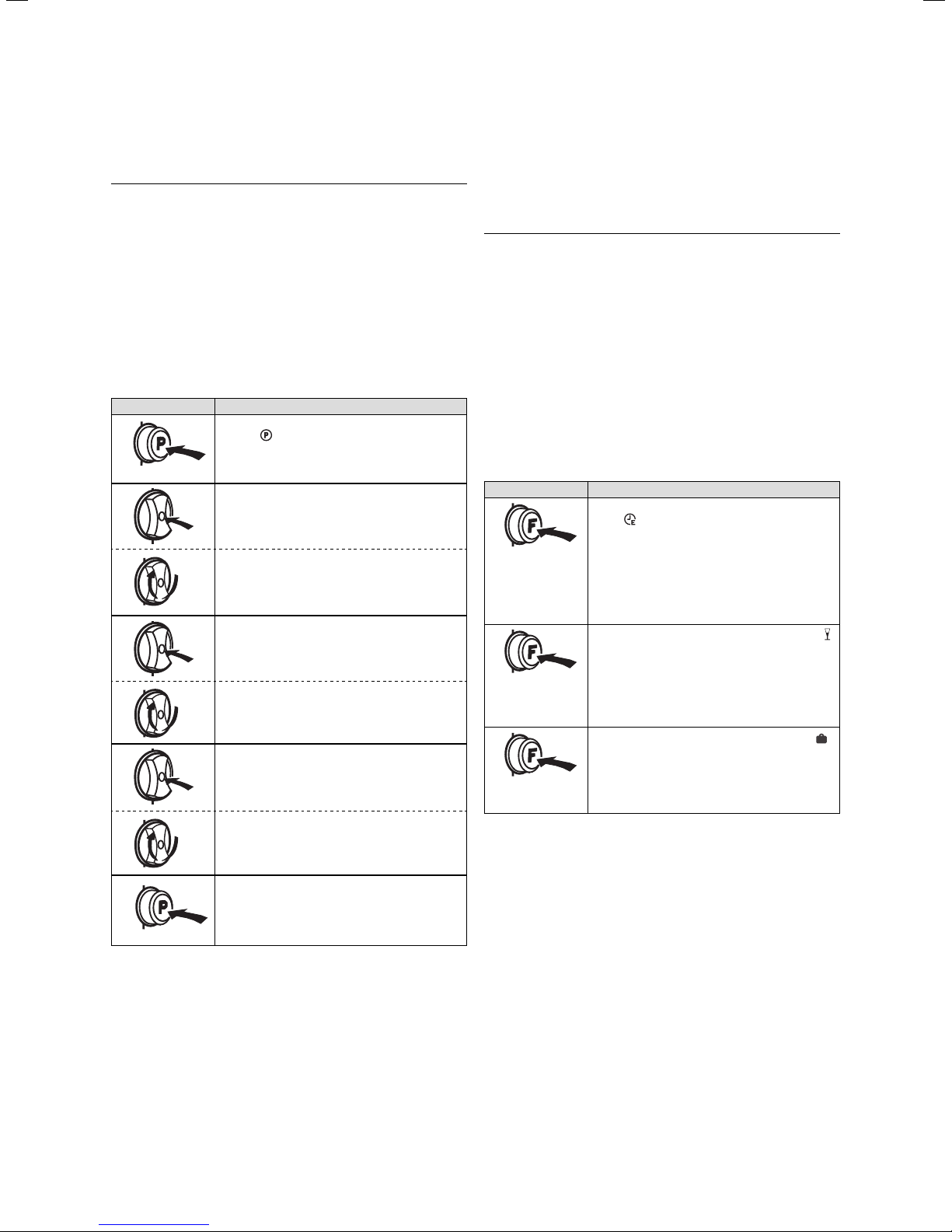
4.7 Programming of the Clock Timer
With the programming button you can change the times
for the timer mode. With activated timer, function recoVAIR will switch between the first and the second stage
(time-controlled)
• Outside the time window: Stage 1 = night operation
• Within the time window: Stage 2 = day operation
It is possible to set up to three different switching-on
and -off times (time windows) for each day of the week.
In the display of the remote control these time windows
are called H1, H2 and H3.
You can combine individual days in groups or a
week block. The following groups are possible:
MO - SU; MO - FR; SA - SU.
Factory-set operating times are:
Time window Day of the
week/Block
H1 MO-FR 6:00 22:00
H1 SA 7:30 22:30
H1 SU 7:30 22:00
Table 4.4 Factory-set operating times
Start time End time
The operating times are set as follows:
• Start with the P button to programme the times.
• Select the time window.
• Select a day or a week block.
• Determine the starting time.
• Determine the end time.
9Operating Manual recoVAIR/3 0020062918_03
Page 10
4 Handling
• Terminate programming of the operating time with
the P button.
Note
h
Within the programming level you can navigate
with the "turn and click technique".
With the "click" - you can change within one program-
ming level from one menu item to
the other. Push the dial several times
in order to reach the desired function. The parameter you want to
change is blinking and an indication
arrow appears.
With the "turn" - you can change the blinking value.
Action Setting of
Activation of the programming level
Display
Select the time window
Click
Turn the dial to select the time window H1 to
Turn
H3.
Select the days of the week or the blocks
for the week
Click
Turn the dial in order to select the individual
Turn
days or week blocks.
Select On and Off times
You select successively the hours and minutes for the switching time by pressing the
Click
dial several times.
Turn the dial in order to change the hours or
Turn
minutes of the switching times.
4.8 Special functions
With the F button (special functions) you can start the
individual special functions.
You select the function by pressing the F button several
times.
Note
h
After the necessary settings have been made,
no confirmation is required 10 seconds after the
last input the indicated function is automatically activated and then the display returns to the
basic display.
By once pressing the "F" button you can deactivate an
active special function.
The deactivation takes 2 seconds. By selecting another
special function the currently activated special function
is terminated.
It is only possible to operate one special function at a
time.
Action Special function
Table 4.6 Special functions
Energy-saving function symbol in the display:
With the energy-saving function the activated
fan stage is set to night mode (stage 1) for a
limited period of time. The user indicates the
period in hours and minutes (minimum
2:30 h). Then the remote control switches
back to the timer mode. Also see figure 4.5
Advance function symbol in the display:
The advance function is used to bridge the
set timer program and activate day mode
(stage 2). The function will remain activated
till the next programmed switch-over to day
mode starts. Also see figure 4.5
Holiday function symbol in the display:
In case the holiday function has been selected, the fan stage is set to a minimum value
for a period to be set (in days). At 0:00 hours,
a day is subtracted from the set period.
Return to basic display
If no new setting is executed for more than
5 minutes, the display will return as well to
the basic display.
Table 4.5 Programming of the time windows
Operating Manual recoVAIR/3 0020062918_0310
Page 11
Handling 4
Troubleshooting 5
4.9 Information Level
Press the information button
to reach the info level.
In addition to identifying the controller, the information
level is used to quickly and easily check the set operating times. Each time window may be individually opened.
If there is no setting action for more than 10 seconds,
the display will return to the basic display.
Action Special function
Table 4.7 Information level
RECO 275/350
Display of the unit type
FILT
Filter days
Indication of the days for which the filter has
been operated since the last filter reset.
AIR
Current air flow supply in m3/h
BYP
Display of the fresh air temperature in oC, if a
bypass has been installed.
DATE
The current date is displayed. Prerequisite is
to activate the calendar first.
Time programme
for the activated heating times
You can call the timer program by pressing
the information button repeatedly.
If the current day of the week is not indicated
in the display, the controller is in the daily
program.
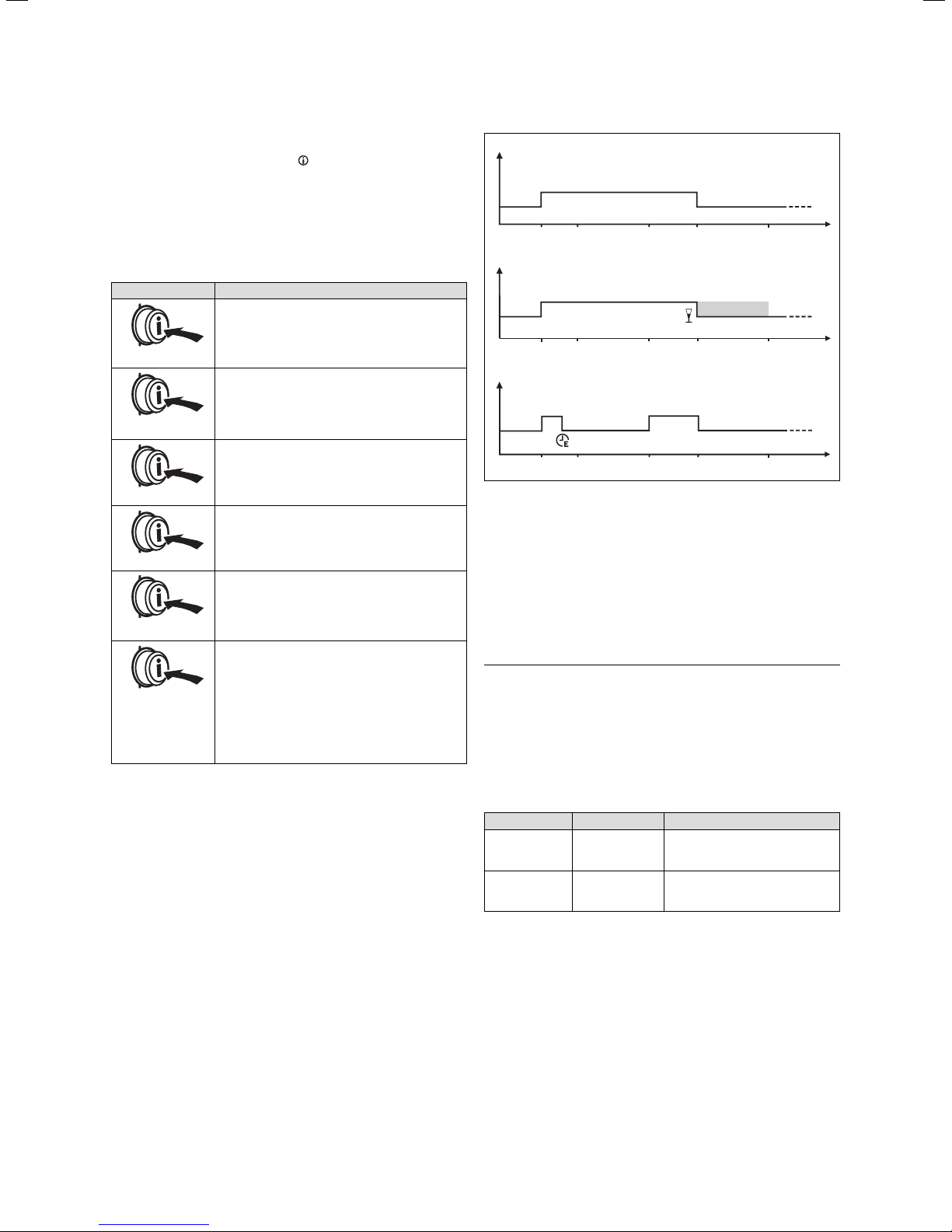
Automatic mode
6:00 22:00
Advance function
6:00 22:0017:0010:00
Energy-saving function
Energy-saving 5h
6:00 22:0017:0010:00 2:00
Fig. 4.5 Comparison of automatic, advance and energy-saving
mode
17:0010:00
2:00
2:00
time
time
time
5 Troubleshooting
Do not try to remedy any other failure than those indicated in table 5.1. For all other failures contact an expert
technician.
Danger!
e
Risk of fatal electric shock from touching live
connections. Pull the mains plug before starting
to work on the device.
• For troubleshooting it is mandatory to pull the mains
plug in order to disconnect the unit from the power
supply.
Malfunction Cause Remedy
No function Mains voltage
Reduced air
flow
Table 5.1 Troubleshooting
interrupted
Filter is heavily
soiled
With the mains voltage re-established the unit will automatically switch on.
Clean or replace the soiled filters as described in chapter 6.
Never interfere or modify the domestic ventilation unit
or other parts of the system.
Only restart the domestic ventilation unit after all failures and malfunctions have been remedied by an expert
technician.
11Operating Manual recoVAIR/3 0020062918_03
Page 12
6 Maintenance
6 Maintenance
Continued efficient operation, reliability and a long service life as well as safety, require inspections and maintenance work to be regularly carried out by an expert
technician on an annual basis.
You must employ a qualified technician to complete
such work.
Caution! You must always ensure that units mounted
high up and units mounted in roof spaces can easily be
reached using suitable equipment.
Caution!
a
We recommend making a maintenance agreement. The operational reliability of the device
can be impaired, resulting in damage to property or personal injury, if maintenance work is
not carried out.
The following must be checked:
– Soiling of the filters (cleaning or replacing the filters)
– Condensate discharge
– Function of the installed bypass unit
You as the owner or user may execute the following
maintenance work yourself:
– Clean and replace the filters in the domestic ventila-
tion unit.
– Clean and replace the filter in the bypass casing
(if installed).
– Clean the fresh air or exhaust air valves in the living
space.
– Reset the time interval for filter replacement in ac-
cordance with section 4.6 "Settings from the basic
display" Caution: Always ensure suitable access equipment is used to gain access to eqipment installed at
high levels or in a loft space.
Caution!
a
Always ensure that the facilities installed higher or in the loft must be well accessible, if required, a suitable equipment must be used.
It depends on the contamination levels how often the filters must be cleaned or replaced. We recommend to
regularly check the filters during the initial operational
period and asses the need to clean them e.g. every
three months. If you then feel that the filters are only
slightly contaminated or dirty, you may extend the interval.
Note
h
Replace the filters at least once a year or after
maximum 2000 operating hours.
You can clean the filters with a vacuum cleaner. If this is
not enough, the filters must be replaced. Cleaning the
filters with water or other liquids is expressly prohibited.
Dispose the used filters with the domestic waste.
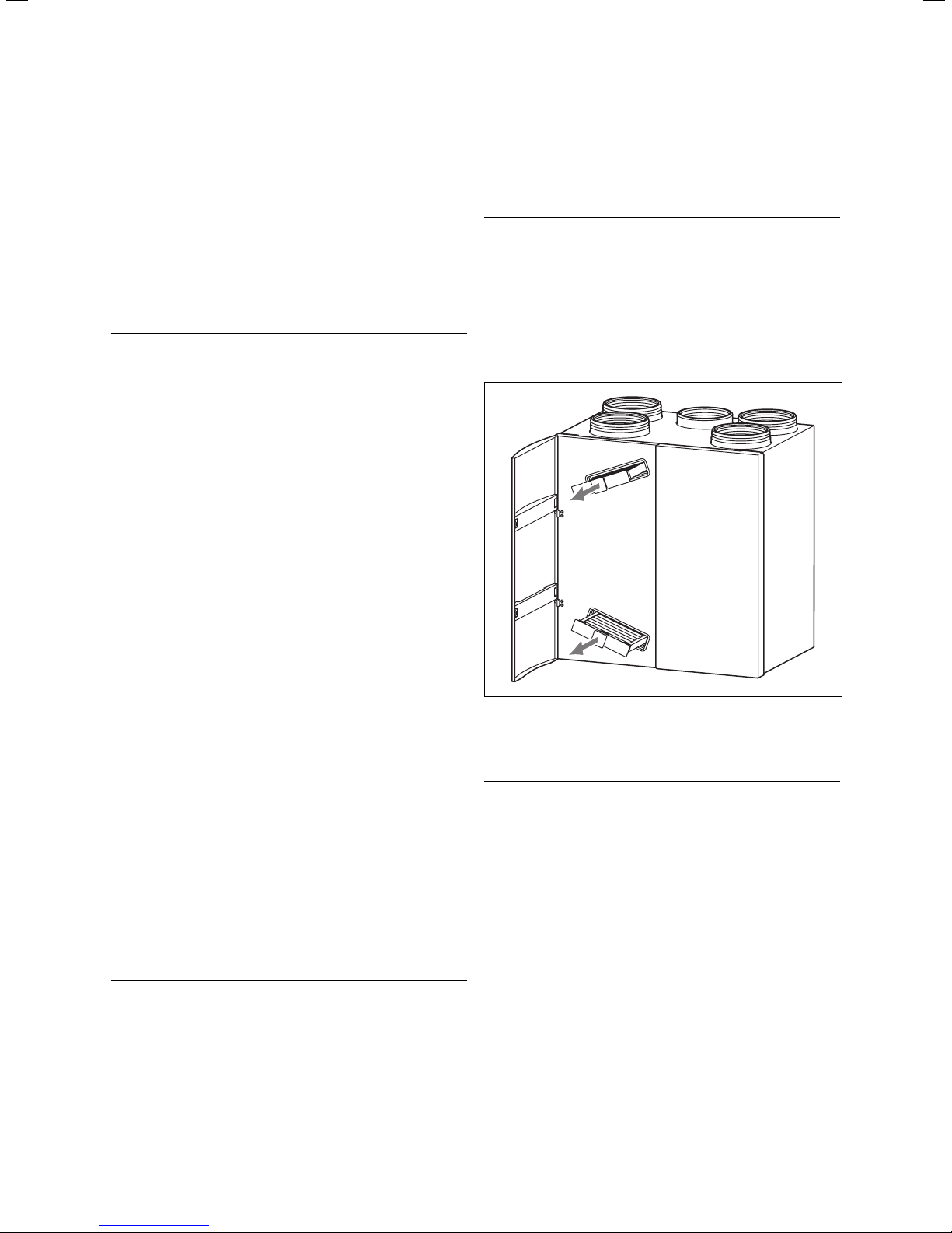
6.1 Cleaning or Replacing the Filter in the
Domestic Ventilation Unit
To check and clean the filters, please proceed as follows:
Danger!
e
Risk of fatal electric shock from touching live
connections. Pull the mains plug before starting
to work on the device.
• Open the left front flap.
• Pull the filter out of the unit.
• Remove the filter handles from the filters.
• Observe the descriptions in the inner side of the door.
Fig. 6.1 Filter replacement
• The filters are to be cleaned or replaced depending on
the degree of soiling.
Caution!
a
Before inserting the filters, please ensure the
correct positioning in order to avoid damaging
of the filters.
• Position the filter handles on the clean or new filters.
On the one side, the filter handles are fitted with guides
which must be pushed into the grooves in the unit.
– The upper filter is mounted with these guide pointing
to the bottom.
– The lower filter is mounted with the guide pointing to
the top.
• Push the filters back into the unit.
• Close the front flap.
• Plug in the mains plug into the plug socket.
The unit is now ready for operation.
Operating Manual recoVAIR/3 0020062918_0312
Page 13
Maintenance 6
Warranty and Customer Service 7
6.2 Cleaning or Replacing the Filters in the
Bypass Casing
To check and clean the bypass filter, please proceed as
follows:
Danger!
e
Risk of fatal electric shock from touching live
connections. Pull the mains plug before starting
to work on the device.
• Pull the filter out of the unit.
• Remove the filter handle from the filter.
• The filter is to be cleaned or replaced depending on
the degree of soiling.
Fig. 6.2 Removing the bypass filter
Caution!
a
When mounting the bypass filter please ensure
the correct positioning in order to avoid damaging the filter.
• Position the filter handle on the clean or new filter.
On one side of the filter handle there are guides, which
must be pushed into the corresponding grooves. The filter is mounted with the guides pointing to the bottom.
• Push the filter back into the unit.
• Plug in the mains plug into the plug socket.
6.3 Filter
Only use the original Vaillant filters.
In addition to the standard filters there are as well available special fine filters. If you intend to use such filters,
please contact an expert technician.
Description Filter class Ordering number
Filterset recoVAIR G3 0020023930
Filter recoVAIR Bypass G3 0020023931
Feinfilterset recoVAIR F6 0020026061
Feinfilter recoVAIR Bypass F6 0020026118
Table 6.1 Filter
Note
h
Replace the filters at least once a year or after
maximum 2000 operating hours.
7 Warranty and Customer Service
7.1 Manufacturer’s Warranty and Liability
Vaillant GmbH warrants that this product is free from
defects of manufacture.
It is covered by a manufacturer’s warranty of
24 months.
The aforesaid manufacturer’s warranty shall be applied
in addition to any legal warranty cover and shall not replace or restrict your legal claims under the Sale of
Goods Act. This warranty shall become effective from
the day of installation, or 2 years after the manufacture
of this system whichever is soonest. This warranty shall
be applicable only for such appliances which have been
installed in UK by a competent installer.
If on the rare occasion that material or fabrication defects arise during the warranty period, the Vaillant
Customer Service will repair these defects free of
charge. It shall be at the sole discretion of the manufacturer’s Customer Service if he is to repair a defective
appliance or to replace it. Work under warranty shall
never cause an extension of the warranty period.
This warranty shall only cover material or manufacturing defects. The warranty shall not be applicable to such
faults or defects caused due to improper installation,
commissioning, handling and use, insufficient maintenance or intervention by unauthorised persons. The
warranty shall become void if such work is executed to
the appliance by other persons than those belonging to
our customer service or an authorised installer. The
aforesaid shall apply as well if parts or components are
incorporated in the appliance or if the appliance is connected to parts or components which have not been approved and certified by Vaillant GmbH. Furthermore, the
aforesaid warranty shall not be applicable to such
claims exceeding the elimination of defects and faults
free of charge, e.g. claims for damages.
Please call our service number 0870-8503073 to report
any defects under warranty.
7.2 Vaillant Service
To ensure regular servicing, it is strongly recommended
that arrangements are made for a Maintenance Agreement. Please contact Vaillant Service Solutions
(0870-8503073) for further details.
13Operating Manual recoVAIR/3 0020062918_03
Page 14

Page 15

For the heating engineer
Installation Instructions
recoVAIR/3
Contents
1 Notes on the documentation ........................16
1.1 Documentation Storage ...................................... 16
1.2 Used Symbols ......................................................... 16
1.3 Manual Validity ...................................................... 16
1.4 CE label .................................................................... 16
2 Device description .........................................16
2.1 Identification Plate ............................................... 16
2.2 Intended Use .......................................................... 16
2.3 Connections .............................................................17
2.3.1 Domestic Ventilation Unit ....................................17
2.3.2 Digital Remote Control recoVAIR ......................17
2.3.3 Condensate Drain Trap .........................................17
2.4 Functionality ............................................................17
3 Safety Instructions and regulations ...........17
3.1 Safety Instructions ................................................17
3.2 General requirements ...........................................17
3.2.1 Preliminary remarks for heat recovery
ventilation products ..............................................17
3.2.2 Related documents ............................................... 18
3.3 Regulations ............................................................. 18
4 Assembly and Installation ........................... 18
4.1 Scope of Delivery .................................................. 18
4.2 Installation Site Requirements .......................... 18
4.2.1 Installation Site of the Domestic
Ventilation Unit...................................................... 18
4.2.2 Installation Site of the Remote Control ..........19
4.3 Assembling ............................................................. 19
4.3.1 Domestic Ventilation Unit ................................... 19
4.3.2 Remote control ..................................................... 20
4.3.3 Bypass ..................................................................... 20
4.4 Measurements ........................................................21
4.4.1 Measurements recoVAIR VAR 275/3
and 350/3 ................................................................21
4.5 Assembly and Installation of the Domestic
Ventilation Unit......................................................22
4.5.1 Mounting of the Fixing Bracket .........................22
4.5.2 Mounting of the Domestic Ventilation
Unit ...........................................................................22
4.5.3 Connection of the Condensed Water Drain ....22
4.5.4 Establishment of Pipe Connections ..................23
4.6 Opening and Closing the Domestic
Ventilation Unit......................................................23
4.7 Mounting and Electrical Connection of
the Bypass (optional) ......................................... 24
4.8 Assembly and Installation of the Remote
Control .................................................................... 25
4.8.1 Establishment of Electrical Connection
of the Remote Control ........................................ 26
4.9 Establishment of Electrical Connection
of the 3-stage Switch (optional) ....................... 28
4.10 Alarm Input (optional) ........................................ 28
4.11 Alarm Output (optional) ..................................... 28
4.12 Function check-out .............................................. 29
5 Start-Up ........................................................ 29
5.1 Adjustment of the Digital Remote Control .... 29
5.1.1 Expert Technician Level ..................................... 29
5.1.2 Service/Diagnostics Level ................................. 30
5.1.3 Testing of the bypass and other functions .....31
5.1.4 Reset to the Factory Setting ...............................31
5.1.5 Setting from the Week to the Day Mode .........31
5.2 Domestic Ventilation Unit Adjustment .............31
5.2.1 Adjustment procedure ..........................................31
5.2.2 Total Air Flow Adjustment ...................................31
5.3 Operator Delivery .................................................32
6 Inspection and maintenance .......................32
6.1 Removing and Cleaning the Filter of
the Domestic Ventilation Unit............................32
6.2 Removing and Cleaning the Heat
Exchanger ...............................................................32
6.3 Cleaning the Condensed Water Drain ..............33
6.4 Cleaning or Replacing the Bypass Filter ........ 34
6.5 Test Operation and Restart ............................... 34
6.6 Spare Parts and Accessories ............................ 34
7 Troubleshooting ............................................35
7.1 Error Messages in the Remote Control .......... 36
7.2 Resistance Values of the Temperature
Sensor ..................................................................... 36
8 Warranty and Customer Service ................37
8.1 Manufacturer’s Warranty and Liability............37
8.2 Vaillant Service ......................................................37
9 Technical Data ............................................. 38
9.1 Domestic Ventilation Unit .................................. 38
9.2 Remote Control .................................................... 38
9.3 Bypass .....................................................................38
9.4 Performance Diagrams ....................................... 39
10 Templates ..................................................... 40
10.1 Templates: Start-up measuring report ...........40
10.2 Template: Filter replacement report ................ 41
10.3 Template: Hygiene check report ...................... 42
Page 16

1 Notes on the documentation
2 Device description
1 Notes on the documentation
The following notes serve as a guide for the entire documentation.
Further documents apply in combination with this installation instructions. We accept no liability for any damage caused by non-observance of these instructions.
1.1 Documentation Storage
Give this installation manual, all accompanying documents and all auxiliary materials, if there are some, to
the operator who will store them so that they are available when required.
1.2 Used Symbols
When operating the unit, please observe the safety instructions in this operating manual!
Danger!
d
Immediate danger to life and limb!
Danger!
e
Risk of death from electric shock!
Caution!
a
Potentially dangerous situation for the product
and environment!
2 Device description
2.1 Identification Plate
Vaillant GmbH Remscheid / Germany
Serial-no. 1234567890xxxxxx
VAR 275 / 3
230V~ 50 HZ
P
V
dP
T
Max
Max
Max.
210 W
275 m³ / h
170 Pa
Max
60 °C
IPX2
Note
h
Useful Information and Hints.
• Symbol indicating the required action
1.3 Manual Validity
This installation manual is valid exceptionally for devices with the following item numbers:
0010006801
0010006802
For the article number of your unit, refer to the identification plate.
1.4 CE label
The CE label shows that this unit complies with the following directives:
– Low-voltage Directive 73/23/EEC, modified with
Directive 93/68/EEC
– EMC-Directive 89/336/EEC, modified by the Directive
91/263/EEC, 92/31/EEC and 93/68/EEC
Bar – Code
Fig. 2.1 Identification plate
The identification plate is positioned below the unit. The
indications given on the identification plate have the following meaning:
Units Value Description
230 V ~50 Hz Mains voltage
P
V
dP
T
Table 2.1 Identification plate
For further information please read section 9 "Technical data".
2.2 Intended Use
The Vaillant domestic ventilation units are built and designed according to accepted safety rules and regulations. Nevertheless, there is still a risk of injury or death
to the user or others or of damage to the device and
other property in the event of improper use or use for
which it is not intended.
210 W Maximum electrical power consumption
max
275 m3/h Maximum air volume flow
max
170 Pa allowable pressure loss of the device
max
60 °C Maximum operating temperature
Max
at V
Max
Installation Manual recoVAIR/3 0020062918_0316
Page 17

Device description 2
Safety instructions and regulations 3
The recoVAIR domestic ventilation unit must be installed by a qualified expert technician, who is responsible for the observance of the existing regulations, rules
and guidelines.
This device is not designed to be used by persons (including children) with limited mental and sensory capabilities or by persons who have not enough experience
and/or knowledge, unless they are supervised by a person who is responsible for their safety or have been instructed by him/her about how to use the device.
Children must be supervised to ensure they do not play
with the unit.
The domestic ventilation units are specifically designed
for the ventilation of residential spaces.
The remote control including the operating mode selector and the timer must only be used for controlling the
domestic ventilation unit as described in these instructions; it is not designed for any other purpose.
Due to high level of dust, operation during the construction phase is not allowed.
Any other or additional use is considered to be improper. The domestic ventilation unit is not suitable for ventilating swimming pools. The manufacturer/supplier
shall not be responsible for any damages resulting from
such improper use.
The user alone bears the risk.
Intended use includes the observance of the operating
and installation manual and all other applicable documents, as well as adherence to the maintenance and inspection conditions.
Caution!
a
Any improper use is forbidden.
2.3.3 Condensate Drain Trap
The attached condensate drain trap must be connected
to the threaded tube under the device. Additionally, an
odour trap is required in the waste water system. For
hygienic reasons, between the drain traps an air gap of
at least 20 mm must be provided.
2.4 Functionality
1
4
2
Fig. 2.2 Air flow diagram
Key
1 Outside air (from outside)
2 Exhaust air (from the living room)
3 Fresh air (to the living room)
4 Outgoing air (to the outside)
3
2.3 Connections
2.3.1 Domestic Ventilation Unit
Necessary connections:
– recoVAIR VAR 275/3: 4 x air duct connections
ø 150 mm, or alternative ø 160 mm and ø 180 mm
– recoVAIR VAR 350/3: 4 x air duct connections
ø 180 mm, or alternative ø 200 mm
– Condensed water drain G 3/4 connection for the con-
densate drain trap
– Electrical connection above mains voltage socket with
230 V 50 Hz mains voltage
2.3.2 Digital Remote Control recoVAIR
On the remote control installation site, the following additional connections are required:
– Control cable from the remote control to the domestic
ventilation unit is a 2-core cable, with cross-section
0,75 mm
The connection must comply with the valid local and national rules and regulations.
2
. Maximum cable length 300 m
3 Safety Instructions and regulations
3.1 Safety Instructions
Installation of the device can be only carried out by a
qualified technician. He/she will be responsible for the
correct installation and start-up.
He/she is also responsible for the inspection and the
corrective maintenance of the device as well as for the
changes in the air flow adjustment.
3.2 General requirements
3.2.1 Preliminary remarks for heat recovery
ventilation products
This appliance should only be used in conjunction with a
propriety ductwork system installed in accordance with
HVCA guide DW144 (steel ductwork) & DW154 (plastic
ductwork).
17Installation Manual recoVAIR/3 0020062918_03
Page 18

3 Safety instructions and regulations
4 Assembly and installation
3.2.2 Related documents
The installation of the heat recovery ventilation unit and
any associated ductwork and outlets must be in accordance with the relevant requirements of the Health and
Safety Document No. 635 (The Electricity at Work Regulations 1989), BS7671 (IEE Wiring Regulations). It should
also be in accordance with the relevant requirements of
the Local Authority, Building Regulations, The Building
Regulations (Scotland), The Building Regulations (Northern Ireland) and the relevant recommendations of the
following:
BS 5588 – Fire precautions in design construction and
use in buildings
BSEN 13141 - Ventilation for buildings. Performance testing of components/products for residential ventilation.
BS EN 1506 - Ventilation for buildings. Sheet metal air
ducts and fittings with circular cross-section.
BS EN 13142 - Ventilation for buildings. Components/
products for residential ventilation. Required and optional performance characteristics
BS EN 12236 - Ventilation for buildings. Ductwork hangers and supports. Requirements for strength
3.3 Regulations
If the system is to be operated with boilers or other gas
appliances which are dependent on the ambient air, the
ventilation must be balanced in accordance to the needs
of the appliance.
The following laws, rules, regulation standards and
guidelines in the valid version must be complied with for
the installation:
– Safety instructions and regulations for low-voltage in-
stallations EN 1010
– EST Good Practice guide 268 – Efficient ventilation of
buildings – A guide to specifiers
– Rules and regulations for air circulation in flats and
habitable areas and residential buildings EN 1087
– Rules and regulations for ventilation systems
DIN 1946
– Any pertaining rules and regulations of the local or
national building authorities
– The present instructions for installation
4 Assembly and Installation
4.1 Scope of Delivery
– Domestic ventilation unit
– Digital remote control recoVAIR
– Mounting set consisting of:
– Fixing brackets 405 x 60 mm
– Condensate drain trap
4.2 Installation Site Requirements
The installation site of the domestic ventilation unit
must be constantly frost-free and dry. The system installation must be planned in detail. Especially pay attention to the positioning of the fresh air and exhaust
air ducts and to include sufficient sound insulation.
Caution!
a
The temperature of the device can be considerably lower than the temperature of the room is
being installed. To avoid undesirable accumulation of condensate, the circulation of fresh and
exhaust air must be provided in the room (basic
ventilation).
4.2.1 Installation Site of the Domestic Ventilation
Unit
Please note the following instructions before choosing
where to install the ventilation unit:
Caution!
a
When mounting the system it is absolutely necessary to ensure the horizontal positioning of
the ventilation unit and an angle of > 0° and < 1°
in vertical position to ensure that the condensation water can easily flow out of the unit.
The domestic ventilation unit is wall-mounted, preferably close to a drain outlet for the condensation water
drain.
– The ventilation unit must be installed with due consid-
eration of the requirement for adequate and practical
air ducting and services (fresh air and exhaust air,
electrical power). Ensure enough space is provided on
top of the unit and at its sides to be able to mount the
required air ducts, additional silencers and bypass
unit.
– The installation site must be selected so that the duct-
work distances to and from the domestic ventilation
unit are as short as possible.
– The wall to which the domestic ventilation unit is to be
mounted must offer sufficient load-carrying capacity
for the weight of the commissioned ventilation unit.
– It is possible that the supplied fixing elements do not
meet the requirements of the installation wall. The required mounting elements must be provided by the
customer.
– The condensed water drain must be connected with
the attached condensate drain trap to the water outlet with the odour trap (siphon).
Accessories (optional)
– Bypass recoVAIR
– Filtersets
Installation Manual recoVAIR/3 0020062918_0318
Page 19

600
300
100
0-1˚
Assembly and installation 4
– When installing the fresh air input and discharge air
ducts you will have to ensure sufficient separation to
avoid that the discharged air being re-circulated into
the fresh air input.
According to VDI 6022 the minimum separation is
10 m.
4.2.2 Installation Site of the Remote Control
– The remote control must be mounted such that there
is enough space around it to complete the electric wiring as well as easy operation of the control.
– The remote control must be installed inside the living
space in an easily accessible place. For further details
see section 4.8.
4.3 Assembling
100 300
1000
Fig. 4.1 Required minimum distances/installation free spaces
– The attached condensed water drain trap is destined
to compensate pressure between the device and the
installation room, for that reason it must always be
filled with clear water.
– For hygienic reasons, it must not be directly connect-
ed to the odour trap of the waste water system. Ensure an air gap of at least 20 mm.
– For the installation, at least 10 cm of free space on the
side of the device must be provided.
– For installation, filter replacement and maintenance
works, about 1 m working space in front of the ventilation unit is needed. Over and beneath the device at
least 30 cm are required (see also fig. 4.1).
– If the domestic ventilation unit is mounted on an inter-
nal wall, do not select a location directly above bedrooms due to possible sound transfer. Always choose
a location above a non-occupied room such as a hall
or bathroom.
– With wood-joist ceilings or similar you can provide ad-
ditional sound insulation by adding insulation between
the joists.
– Always ensure that the condensation water drain is
free running.
– To avoid annoyance by excessive noise select a
sound-absorbing hose for final connections from the
unit to the air outlets.
– Install a silencer. This will help to neutralise possible
noise transmission between the unit and the air ducting and reduce annoyance by noise.
– Keep the air supply inlet at a sufficient distance from
discharge air, exhaust air and drain ventilation. Comply with the legal building rules and regulations.
4.3.1 Domestic Ventilation Unit
14
13
12
11
10
9
8
Fig. 4.2 Assembling recoVAIR VAR 275/3 and 350/3
Key
1 Air duct Outgoing air
2 Air duct Fresh air
3 Fresh air fan
4 Circuit board
5 Exhaust air fan
6 Condensate drain outlet
7 Electrical connection of
the 3-stage switch
8 Outside air filter
9 Heat exchanger
10 Exhaust air filter
11 Mounting point Front
cladding
12 Air duct Exhaust air
13 Air duct Outside air
14 Bypass connection
1
2
3
4
5
6
7
The unit is equipped with a frost protecting sensor.
This sensor measures the temperature of the discharge
air. The fresh air fan is switched off if the discharge air
temperature falls below 3 °C.
Once switched off, the fresh air fan is only switched on
again when the discharge air temperature has risen
above 8 °C.
19Installation Manual recoVAIR/3 0020062918_03
Page 20

4 Assembly and installation
If the protection circuit is activated against the low
pressure (STOV, see section 5.1.1), the frost protection
sensor switches both ventilators off.
The outside air flow may be much cooler than the temperature of the discharge air measured by the frost protection sensor before the anti-freeze monitoring device
is activated. Its operation is possible up to -7 °C outside
temperature.
4.3.2 Remote control
The control elements of the remote control are explained in the operating manual in section 4.4.
4.3.3 Bypass
Vaillant GmbH Remscheid / Germany
Serial-no. 1234567890xxxxxx
Bypass VAR 275 - VAR 350
12 V DC
P
3 W
Max
3
Fig. 4.3 Bypass Installation
Key
1 Filter
2 Ventilation flap
3 Air inlet from outside
IPX2
nur zu verwenden mit recoVAIR 275 / 350
12
only to use with recoVAIR 275 / 350
alleen te gebruiken met recoVAIR 275 / 350
utiliser seulement avec le recoVAIR 275 / 350
Kan kun bruges sammen med recoVAIR 275/350
Bar – Code
Fig. 4.4 Identification plate Bypass
You can find the identification plate on the top of the
device. The indications given on the identification plate
have the following meaning:
Units Value Description
12 V DC Voltage supply
P
3 W Maximum electrical power consumption
max
Table 4.1 Explanation of bypass identification plate
Installation Manual recoVAIR/3 0020062918_0320
Page 21

4.4 Measurements
4.4.1 Measurements recoVAIR VAR 275/3 and 350/3
182
182
Assembly and installation 4
441
53EF
ØC (4 x)
41 A
986
709
Y- Y
450
115
403
200
315
645
B
14 2 400
D
680
Fig. 4.5 Measurements recoVAIR VAR 275/3 and 350/3
recoVAIR VAR 275/3 recoVAIR VAR 350/3 Remarks
A 77 127
B 471 521
C ø 150/ø 160/ø 178 ø 180/ø 198 Pipe diameter to be selected for all 4 air connections
D ø 150/ø 160/ø 178/ø 198 ø 150/ø 160/ø 178/ø 198 Pipe diameter to be selected for the bypass connection
A 102 122
F 210 240
Table 4.2 Table of dimensions for recoVAIR VAR 275/3 and 350/3 (dimensions in mm)
21Installation Manual recoVAIR/3 0020062918_03
Page 22

4 Assembly and installation
4.5 Assembly and Installation of the Domestic
Ventilation Unit
• First mount the domestic ventilation unit and the re-
mote control, and then proceed to the electrical connections.
• Ensure there is enough space for assembly at the
sides of the domestic ventilation unit (at least 10 cm).
This domestic ventilation unit is solely intended for vertical wall mounting.
4.5.1 Mounting of the Fixing Bracket
A fixing bracket is supplied for the wall mounting of the
unit, the unit is hooked onto it.
Caution!
a
When mounting the system it is absolutely necessary to ensure the horizontal positioning of
the ventilation unit and an angle of > 0° and < 1°
in vertical position to ensure that the condensation water can easily flow out of the unit.
4.5.2 Mounting of the Domestic Ventilation Unit
Danger!
d
If not mounted correctly, the unit may fall off.
Ensure that the wall offers the appropriate load
carrying capacity and that the proper fixing
means are used for secure mounting. It is possible that the attached mounting set with the
fixing screws and wall plug is not suitable for
every wall.
Danger!
The ventilation unit weighs about 35 kg. When
hooking the unit onto the fixing bracket, never
lift the unit alone.
• Position the domestic ventilation unit above the
bracket and then hook it onto the clips.
• The unit must have fitted absolutely horizontal and
vertical.
4.5.3 Connection of the Condensed Water Drain
• Join the connecting piece for the condensate drain
trap to the connection outlet on the bottom of the domestic ventilation unit.
• Connect the attached condensate drain trap with the
connection piece (see fig. 4.7).
min 945
0-1˚
Fig. 4.6 Mounting of the fixing bracket
• Determine the installation site (see section 4.2 "Requirements of the installation site").
• Drill the holes for the fixing screws and position the
wall plugs.
• Screw the fixing bracket horizontally to the wall.
Fig. 4.7 Assembly of the condensate drain trap
Installation Manual recoVAIR/3 0020062918_0322
Page 23

Assembly and installation 4
Caution!
a
For the condensate discharge of the ventilation
appliance a second drain trap is required!
Caution!
For hygienic reasons, the condensate drain trap
must not be directly connected to the waste
water system.
An air gap of at least 20 mm must be provided.
A wrongly installed condensate outlet can lead
to condensate accumulation and to an uncontrollable escape of condensate. Use of the customer service and possible subsequent damages are not covered by the Vaillant warranty.
airVENT
> 2 cm
4.6 Opening and Closing the Domestic Ventilation
Unit
The domestic ventilation unit is equipped with a fixed
front cladding with a pivoting door to the left. Behind
this door there are the filters. For mounting and maintenance work on the unit it is necessary to remove the
front cladding. This is how to do it:
Danger!
e
Risk of fatal electric shock from touching live
connections. Pull the mains plug before starting
to work on the device.
Note
h
Remove filters from the device first because
they are fixed in the front cladding.
• Open the left door on the unit front.
• Pull both filters out of the unit and then close the
door (fig. 4.9, pos. a)
• Loosen and remove the screw on the left toggle-type
fastener below the unit (fig. 4.9, pos. b).
Then open both toggle-type fasteners (fig. 4.9, pos. c).
• Pull the lower part of the front cladding close to you
(fig. 4.9, pos. d).
• Now lift the front cladding above the top fixing points
(fig. 4.9, pos. e).
airVENT airVENT
Fig. 4.8 Correct installation of the condensate outlet
4.5.4 Establishment of Pipe Connections
• Before executing the final connection check the air
ducts are still clean. If necessary, clean the air ducts.
• Only then connect the air ducts to the domestic ventilation unit.
• Connect the air ducts individually as shown to the
connections on top of the unit.
Caution!
a
Air ducts must be tightly connected with the
ventilation unit - use suitable accessories or
sealing material. Insulation of the fresh air and
outgoing air ducts must be diffusion resistant.
To close the ventilation unit, carry out the steps in reverse order. Always ensure the screw is replaced into
the left hand toggle after re-assembly to avoid unauthorised access to the unit.
Note
h
Ensure that after the repeated assembly the
screw is inserted into the left lever again to
prevent access by unauthorised persons.
23Installation Manual recoVAIR/3 0020062918_03
Page 24

4 Assembly and installation
a
a
4.7 Mounting and Electrical Connection
of the Bypass (optional)
The bypass must be mounted in accordance with the installation scheme (see section 2.4 "Functioning") within
the outside air flow in order to bypass the domestic ventilation unit.
Danger!
e
Risk of fatal electric shock from touching live
connections. Pull the mains plug before starting
to work on the device.
Danger!
e
Risk of fatal electric shock from touching live
connections. Improper electric installation may
cause accidents. Therefore it is absolutely
mandatory to have a competent person complete the electric installation.
Note
h
The bypass must be first electrically connected
because the electric lines are not accessible
after the mounting.
• Open the domestic ventilation unit as described in
section 4.6.
• Remove the plug from the middle air connection by
pushing it upwards from the inside (see fig. 4.10).
b
c
e
d
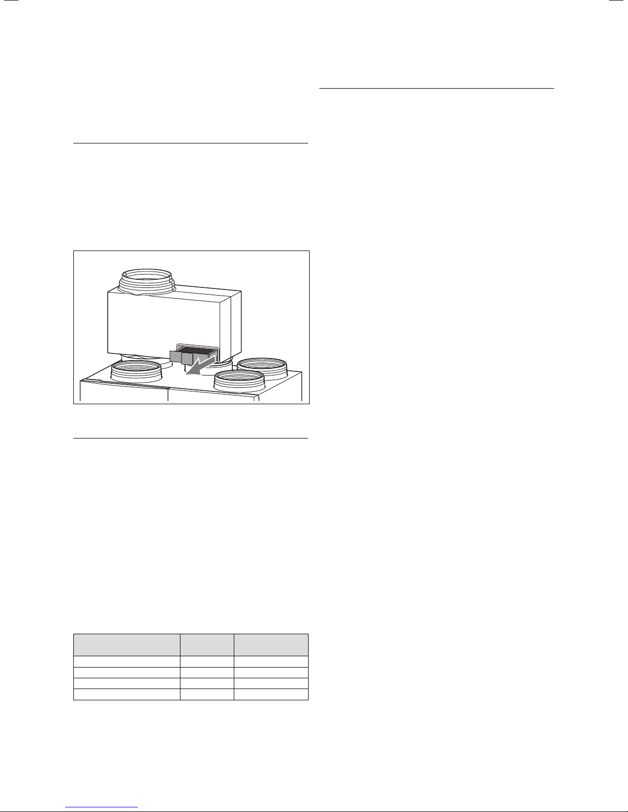
Inside the bypass air connection in the domestic ventilation unit, there is a 10-pole connector to which the bypass plug is connected.
You will find a plug in the bag in the casing wall. Pull the
plug out of the bag of the casing wall.
• Release the cable with the 10-pin connector from the
casing wall and connect the bypass plug with the connector (fig. 4.10).
Fig. 4.9 Opening and closing of the domestic ventilation unit
Fig. 4.10 Electrical connection of the bypass
Installation Manual recoVAIR/3 0020062918_0324
Page 25

Assembly and installation 4
To install the temperature sensor, proceed as follows
(see fig. 4.10):
• Remove the plug from the sensor hole in the outside
air duct.
• Push the temperature sensor through the hole into
the exhaust air duct.
Caution!
a
To ensure the correct bypass function the temperature sensor must project at least 25 mm
into the exhaust air flow.
4.8 Assembly and Installation of the Remote
Control
Normally the best siting of the remote control is in the
main living space at an inside wall at a height of about
1.5 m. There the controller is able to detect the circulat-
ing ambient air clearly and unimpeded from furniture,
curtains or other external influences. The position
should be selected so that neither air drafts from the
door or the window nor heat sources such as radiators,
chimney wall, TV or solar irradiation may directly influence the controller.
A connection with the ventilation unit is established via
a 2-core connection cable.
1
4
2
5 mm
2
Fig. 4.11 Mounting position of the temperature sensor
After completing the electrical connection of the bypass, you can mount the bypass unit.
• Push the bypass into or over the both outside air connections of the device as shown in fig. 4.10.
Make sure that the filter unit is aligned towards you.
• Check that the bypass is completely inserted.
• Plug in the mains plug into the plug socket.
5
2
4
Fig. 4.12 Mounting of the remote control
3
Key
1 Casing
2 Mounting holes
3 Wall base
4 Cable bushings
5 Terminal strip
• Pull the casing (1) of the remote control from the wall
base (3).
• Make two mounting holes (2) with diameter 6 mm
(as shown in fig. 4.12) and insert the provided dowels.
• Pull the connection cable through one of the cable
openings (4).
• Fasten the wall base to the wall using the two supplied
screws.
• Connect the cable to the corresponding terminals
(eBUS "+" and "-") on the terminal connecting
strip (5).
• Place the casing (1) on to the wall base (2) such that
the pins at the back of the upper part locate into the
seats.
25Installation Manual recoVAIR/3 0020062918_03
Page 26

4 Assembly and installation
• Press the casing to the wall base till it locates, taking
care not to bend the controller connection pins. Make
sure that you do not bend the contacts.
4.8.1 Establishment of Electrical Connection of the
Remote Control
Danger!
e
Risk of fatal electric shock from touching live
connections. Pull the mains plug before starting
to work on the device.
Note
h
To prevent accidents, electric installation can
only be carried out by a qualified expert technician.
The remote control is connected to the domestic ventilation unit via a two-core cable. Communication is done
via a 2-pole eBUS. The eBUS connector is sized to accommodate wiring of 2 x 0.75 mm
2
(recommended). It is
possible to interchange the connections without affecting communication. This connection is at the bottom of
the unit.
• Connect the control cable as shown in Fig. 4.13 to the
eBUS-clamps "+" and "-".
BUS
Swi
t
ch
0
D
H
Fig. 4.13 Establishment of the electrical connection of the re-
mote control
Installation Manual recoVAIR/3 0020062918_0326
Page 27

Assembly and installation 4
Mains connection
BUS connection
Switch 2
Switch 1
0 - 10 V Control
signal (analog)
Alarm input
Alarm output
X 15
X 16
230 V~
F4
2AT
Bus
Switch 2
Switch 1
Analog
Error In Err. Out
PC
connection
N
L
-+ 12 12DO
H
DO
H
+
X 1X 9
white whitewhite
N
L
Freh air fan
Exhaust air fan
N
L
X 2
Control signal
X 3
X 4
X 5
0 - 10 V
Hz
Gnd
Control signal
0 - 10 V
Hz
Gnd
Temperature sensor EAO
ϑ
(Frost protection sensor)
Bypass Motor
M
ϑ
Temperature sensor EAI
ϑ
Temperature sensor SAO
ϑ
Temperature sensor SAI
red blue white
X 10
X 11
white white white
X 12
X 13
10
white
X 14
X 17
9
5
4
8
3
7
2
6
1
X 6
X 7
Fig. 4.14 Wiring diagram
X 8
27Installation Manual recoVAIR/3 0020062918_03
Page 28

4 Assembly and installation
4.9 Establishment of Electrical Connection of the
3-stage Switch (optional)
In addition to the standard control unit, you can also use
a universal 3-stage switch to control the domestic ventilation unit. This must be potential-free (no voltage).
• Connect three lines as shown in fig. 4.15 to the clamps
"0↓", "D↑" and "H↑".
The following switch positions are possible:
Position Function Electrical contact
1 ("0") Control system with remote
2 ("D") Day position (fans stage 2) 0↓ connected to D↑
3 ("H") HIGH position
Table 4.3 Switch positions of the 3-stage switch
0
Switch
0 D
H
control
(fans stage 3)
BUS
-
H
D
+
0↓ open
0↓ connected to H↑
0
D
H
4.10 Alarm Input (optional)
The alarm input (connection "X 14" on the board) is
bridged when the unit is delivered. If the connection is
undone with an external potential-free switching contact
(break contact), both fans will be switched off. On the
display of the remote control you will find the message
"LOCK".
Danger!
e
Risk of fatal electric shock from touching live
connections.
Pull the mains plug before starting to work on
the device.
• Remove the unit front cladding as described in
section 4.6.
• Now place the 2-core cable (minimum 0.35 mm
2
) in
the respective cable routing to the PCB.
• Connect the lines to the connection "X 14" (alarm
input) in accordance with figure 4.14 "Wiring scheme".
Note
h
When the contact is opened, the word "LOCK"
appears on the display of the remote control.
The fans on the domestic ventilation unit are
then switched off.
4.11 Alarm Output (optional)
The alarm output (connection "X 16" on the board) is
made of a potential-free switching contact with a resistive load (Ohm) of maximum 2 A.
1
Fig. 4.15 Electrical connection of the 3-stage switch
Key
1 Strain relief alarm outlet
40 mm
Ø 4,5 - 10 mm
Fig. 4.16 Removal of cable insulation
• Remove the cable insulation as shown in fig. 4.16.
• Lead the cable through the strain relief (see fig. 4.15)
and screw them together.
Installation Manual recoVAIR/3 0020062918_0328
Page 29

Assembly and installation 4
Start-up 5
An alarm will be triggered
– If the time set for the filter replacement has expired.
The duration is set under the installer level option on
the remote control.
– If one of the error messages described in section 7.1 is
indicated in the remote control display.
Danger!
e
Risk of fatal electric shock from touching live
connections. Pull the mains plug before starting
to work on the device.
• Remove the unit front cladding as described in
section 4.6.
• Now place the 2-core cable (minimum 0.35 mm
2
) in
the respective cable routing to the PCB.
• Connect the lines to the connection "X 16" (alarm output) in accordance with figure 4.14 "Wiring scheme".
4.12 Function check-out
Once all supply lines are correctly installed in accordance with the wiring scheme, check the functions of the
remote control, the domestic ventilation unit and the
bypass (see section 5.1.3). When doing so, note that the
unit must not be started until all ventilation ducts are
connected to the unit and the unit and all ductwork are
completely sealed.
In the sections 4.4 to 4.8 of the operating manual you
will find in detail all the settings for the individual operating modes and the special functions. For testing functions proceed as follows:
• Select the "night" operating mode and check that the
fans in the domestic ventilation unit are operating at
low output.
• Select the "day" operating mode and check that the
fans in the domestic ventilation unit are operating at
medium output (AIR2).
• Activate the special function "advance". Check that
the fans in the domestic ventilation unit are operating
at medium output (AIR2).
• If the output stages are not correctly switched, you
must check the wiring on the terminals of the remote
control and the domestic ventilation unit.
5 Start-Up
The start-up and the operation of the unit as well as instruction to the user must be done by a competent person.
Please note that the device can only be started up if all
ventilation pipes of the device are connected and the
entire device is closed.
As part of the start-up it is necessary to adjust the domestic ventilation unit.
The domestic ventilation units are delivered ex factory
with basic setting of both fans. As each fresh air and exhaust air installation is different and thus offers different external resistance in the air ducting you will have
to separately adjust the fresh air and the exhaust air fan
to suit.
You can adjust the domestic ventilation unit using the
remote control. Below are the necessary steps.
5.1 Adjustment of the Digital Remote Control
To optimally match the system parameters to the required conditions it is necessary to set these parameters with the remote control. The system parameters
are located in an upper operation level and should only
be set by an expert technician.
5.1.1 Expert Technician Level
Hold down the P button for about 10 seconds to go to
the installer level. The
symbol appears on the display.
Then, by pressing the dial, it is possible to select the
functions. The functions shown in table 5.1 can be
scrolled through one after the other.
To change the parameters just turn the dial.
If you want to return to the basic display, shortly press
the P button.
The adjustable air volume flows apply jointly to fresh air
and exhaust air.
Action Display Meaning
AIR1
press for
10 sec.
AIR2
Click
Table 5.1 Functions in the installer level
Set volume flow night
1st stage
recoVAIR VAR 275/3 350/3
Default setting m
3
Min m
/h 50 70
3
/h AIR2 AIR2
Max m
Set volume flow for the
non-programmed periods.
Set volume flow day
2nd stage
recoVAIR VAR 275/3 350/3
Default setting m
3
Min m
/h AIR1 AIR1
3
Max m
/h HIGH HIGH
Set volume flow for the programmed
periods.
3
/h 80 105
3
/h 165 210
29Installation Manual recoVAIR/3 0020062918_03
Page 30
5 Start-up
Action Display Meaning
HIGH Set volume flow, 3rd stage
recoVAIR VAR 275/3 350/3
Default setting m
Click
Min m
3
Max m
Must value of the volume flow after the
activation of the special function "Advance Mode" with the key F.
AIR4 Set volume flow holiday
recoVAIR VAR 275/3 350/3
Click
Default setting m3/h 60 75
3
Min m
Max m
Set volume flow after activation of the
special function "holidays" with the F
button, additionally in "OFF" mode.
AIR5 Min. volume flow with activated
bypass
recoVAIR VAR 275/3 350/3
Click
Default setting m
3
Min m
Max m
Minimum volume flow when the con-
nected bypass switches to summer
mode (without heat recovery).
STOV Protective switching against
negative pressure
recoVAIR VAR 275/3 350/3
Click
Factory setting OFF OFF
ON = If one fan fails, the other fan is
also deactivated.
This protective switching prevents negative pressure as a result of only disconnecting the supply fan. If the protective switching against the low pressure is activated, both fans are
switched off by the frost protection
function.
HEAT No function
3
/h 275 350
/h AIR2 AIR2
3
/h 325 400
/h 50 70
3
/h AIR2 AIR2
3
/h 110 140
/h AIR1 AIR1
3
/h HIGH HIGH
Action Display Meaning
C-AIR Set volume flow correction
recoVAIR VAR 275/3 350/3
Default setting in % 0 0
Click
Min in % -50 -50
Max in % +50 +50
Adjustment of the set volume flow for
fresh air in order to produce a slightly
negative pressure in the building. At
low temperatures it prevents ice formation due to condensation water on
the doors and windows.
C-RT Room temperature correction
recoVAIR VAR 275/3 350/3
Click
Factory setting in °C 0 0
Min in °C -3 -3
Max in °C +3 +3
Correction of the room temperature
indicated on the display of the remote
control.
DAY Desired value of the current day*
recoVAIR VAR 275/3 350/3
Factory setting 0 0
Click
Min 0 0
Max 31 31
MON Desired value of the current month*
recoVAIR VAR 275/3 350/3
Factory setting 01 01
Click
Min/month 01 01
Max/month 12 12
YEAR Desired value of the current year*
recoVAIR VAR 275/3 350/3
Factory setting 2005 2005
Click
Min/year 2000 2000
Max/year 2159 2159
Table 5.1 Functions in the Installer level (continued)
* Setting will be required if the automatic switching
from summer to winter time is to be activated.
Click
FILT Days till the next filter replacement
recoVAIR VAR 275/3 350/3
Click
Default setting/days 180 180
Min. days 30 30
Max. days 180 180
Adjusted in 30 day steps to which the
indication "FILT" is shown on the remote control display. (Alarm output is
closed)
POL1
No function
POL2
Click
Table 5.1 Functions in the Installer Level (continued)
5.1.2 Service/Diagnostics Level
The service/diagnostics level should help the installer
during the service.
Keep the P button and the dial simultaneously pressed
for about 3 seconds to reach the service/diagnostics
level. The display will show the symbols
. By pressing
the P button you will return to the basic display. You
can display the following functions / information:
Installation Manual recoVAIR/3 0020062918_0330
Page 31

Start-up 5
Action Display Meaning
BYPONBypass switches to summer
+
mode
3 Sec.
Turn
Turn
Turn
Turn
Turn
Turn
Click
Click
Click
Click
Turn
Table 5.2 Functions of the service/diagnostics level
ALARONAlarm output is activated
HEATONNot activated
SAO/*
xx oC
EAO/
xx oC
EAI*
xx oC
SAI/*
xx oC
AIR/
xx m3/h
APPL/
3 / 4
Display Display test: All symbols of the
VER1/
x.xx
VER2/
x.xx
(contact closed).
Display of fresh air temperature
(Supply Air Out)
Display of the discharge air
temperature at the frost protection sensor (Exhaust Air
Out)
Display of the exhaust air temperature (Exhaust Air In)
Display of the outside air temperature (Supply Air In)
Current air volume flow indication in the ventilation unit. By
turning the dial it is possible to
change the air quantity during
the test mode.
Display of the unit type
3 = recoVAIR VAR 275/3
4 = recoVAIR VAR 350/3
Turn the dial to select the unit
type.
display are indicated, however,
not all symbols of recoVAIR
have a meaning.
Display of the software version
of the remote control
Display of the software version
of the recoVAIR PCB
Return to basic display
* These values can only be called with a bypass unit installed.
5.1.3 Testing of the bypass and other functions
Go to the service/diagnostics level as described in
section 5.1.2. Now test successively all functions in accordance with table 5.2. If the bypass is not connected
or if a sensor is defective, the display will show the symbol "-".
5.1.4 Reset to the Factory Setting
• Press the P button for 15 seconds to reset the control-
ler to the default setting.
As soon as the display lights up twice, the controller is
completely re-set to its default settings. This means
that you will have to perform all individual settings
again.
5.1.5 Setting from the Week to the Day Mode
The remote control is factory-set to a week program. It
may be switched if required to the day mode.
• Press the F button for 10 seconds to change the set-
ting of the remote control to day mode.
5.2 Domestic Ventilation Unit Adjustment
5.2.1 Adjustment procedure
First of all ensure that the overall air flow calculated for
the installation is reached by the system. Then adjust
the air flow rates for the individual living spaces. Then
finally adjust the individual air flow distribution within
each living space.
5.2.2 Total Air Flow Adjustment
First adjust the desired air quantity calculated when the
system was designed with the remote control for all operating modes (installer level). Proceed step by step as
described in table 5.1 in section 5.1.1. In the above-mentioned table you will find the information for the desired
values.
Note
h
The planned air flow must be in the in the day
mode (2nd stage) because this is the standard
operation mode.
Adjusting the air quantities at the system
1. Adjust all the exhaust and fresh air valves in the living
rooms to the middle opening of about 50 %. Then
proceed in accordance with the instructions given in
the manufacturer operating manual.
The air speed must not exceed 1.5 m/s at a distance of
50 cm from the valve.
2. Make sure that all valves in the existing air duct mani-
folds are completely opened.
3. Switch the domestic ventilation device into the opera-
tion mode "day mode" using the remote control.
31Installation Manual recoVAIR/3 0020062918_03
Page 32

5 Start-up
6 Inspection and maintenance
4. Measure the partial air flow at the strings with control
dampers if there are some available. Correct these
settings if required by adjusting the control dampers.
5. Open, if necessary, air inlet and air outlet valves if the
desired total air flow has not been reached.
6. Raise the ventilator revolution speed using the values
in table 5.1 if the total air flow is too low.
7. Go to the installer level in the remote control by
pressing the programming key P for 10 seconds.
8. Press the dial until "C-AIR" appears on the display.
9. Correct the inlet air flow by turning the dial until the
inlet and the outlet air volume are equal
(see table 5.1).
5.3 Operator Delivery
Completely fill in the attached measurement report
(see chapter 10) and hand it over to the operator.
6 Inspection and maintenance
Note
h
Replace the filters at least once a year or
after maximum 2000 operating hours. (see
section 6.6 "Spare parts and accessories"). If
the filters are heavily soiled, they should be replaced at shorter intervals.
6.1 Removing and Cleaning the Filter of the
Domestic Ventilation Unit
If the filters are not strongly soiled, you may clean them
with a normal vacuum cleaner.
If this is not enough, the filters must be replaced. Cleaning the filters with water or other liquids is expressly
prohibited.
In the operating manual in section 6.1 you will find a detailed description on how to replace the filters.
6.2 Removing and Cleaning the Heat Exchanger
To clean the heat exchanger it must be removed.
Danger!
e
Risk of fatal electric shock from touching live
connections. Pull the mains plug before starting
to work on the device.
Caution!
a
When removing and replacing the heat exchanger take care not to damage it.
Do not grab with your hand or with any objects
directly holding the heat exchanger fins. Any
damage will lead to premature wear in the system.
Hint
A qualified person in the area of the air pollution control should carry out regular inspections. The first inspection should be performed
3 months after start-up.
Note
To avoid damaging the unit due to improper
work, the following maintenance work must be
executed by competent and trained personnel.
The functional operation of the domestic ventilation unit
requires it to be serviced once per year. This includes
the following:
• Check the general condition of the unit.
• Remove any dirt and soiling at the unit.
• Clean or replace soiled filters.
• Clean the condensate outlet and check if the duct is
free.
• Clean soiled fans.
• Check the function of the unit, the remote control and
the bypass.
Fig. 6.1 Removing the heat exchanger
• Open the domestic ventilation unit and remove the filters and the front cladding as described in section 4.6.
• Take the heat exchanger with both hands at the edges
without damaging the fins.
• Then carefully pull out the heat exchanger.
Installation Manual recoVAIR/3 0020062918_0332
Page 33

Inspection and maintenance 6
• Clean the heat exchanger with a washing liquid with
neutral pH and lukewarm water. Then rinse it again
with clear lukewarm water.
• Leave the heat exchanger dry before replacement.
Caution!
a
To clean the heat exchanger use only a washing
liquid with neutral pH and lukewarm water.
Other detergents, especially acidic detergents
(such as vinegar cleaner), damage the unit.
With the removed heat exchanger check as well if the
condensation water drain (section 6.3) is dirty.
• Slide the heat exchanger back into the unit. Take care
that the heat exchanger correctly fits into the guide
rails at the top and bottom of the housing and that it
is not installed off centre.
Caution!
a
The heat exchanger must be flush with the
front side of the EPP body. A protruding heat
exchanger can cause leakages and condensate
escape.
6.3 Cleaning the Condensed Water Drain
To clean the condensation water drain, firstly remove
the heat exchanger (see section 6.2)
• Unscrew the condensation water hose from the bottom of the unit.
• Check if the drain is free.
Clean it if is blocked.
• If required, clean any dirt in the drain pan.
• Clean the condensate drain trap and fill it with drinking water
Fig. 6.2 Condensation water drain
33Installation Manual recoVAIR/3 0020062918_03
Page 34

6 Inspection and maintenance
6.4 Cleaning or Replacing the Bypass Filter
Danger!
e
Risk of fatal electric shock from touching live
connections. Pull the mains plug before starting
to work on the device.
The domestic ventilation unit may be equipped with a
bypass, if required.
Demounting, control and cleaning of the bypass-filter
are described in detail in the operating manual in
section 6.2.
6.5 Test Operation and Restart
After the inspection/maintenance work check the correct functioning of the unit:
• Check that the unit casing is correctly closed.
• Insert the mains plug into the plug socket and start
the unit.
• Check the correct function of the unit.
• Check the correct function of the remote control.
6.6 Spare Parts and Accessories
In order to continuously ensure the correct function of
the Vaillant unit and not to change series-production
status it is absolutely mandatory only to use genuine
Vaillant spare parts for the maintenance and maintenance work.
Description Filter class Ordering number
Filterset recoVAIR G3 0020023930
Filter recoVAIR Bypass G3 0020023931
Feinfilterset recoVAIR F6 0020026061
Feinfilter recoVAIR Bypass F6 0020026118
Table 6.1 Accessories
Installation Manual recoVAIR/3 0020062918_0334
Page 35

7 Troubleshooting
Troubleshooting 7
The faults listed below may only be rectified by an expert technician.
• Make sure the parts are correctly fitted and that their
• Troubleshooting is successful if the unit operates correctly.
• Only use genuine spare parts for repairs.
original position and alignment are retained.
Malfunction Cause Remedy
The unit does not operate
Unit operation is very
loud even at the minimum fan speed
None or insufficient
fresh air supply
No or insufficient
exhaust air flow
(i.e. in the bathroom
the mirror stays
fogged up)
Bypass summer mode
does not work
Noise in the condensation water drain
trap
Water dripping from
the unit
Fresh air too cold Exhaust air and fresh air flows not balanced.
No fresh air or exhaust air (only one
fan running)
Odours from the
kitchen/WC enter into
other rooms
Sound transmitted between the rooms
Planned air flow not
reached at the startup
Noise in the unit after
replacing the fan.
Table 7.1 Troubleshooting
Temporary interruption of the mains voltage supply or no supply at all. Power supply circuit breaker tripped. Electricity disconnector was activated.
Fuse F1 in the unit is defective.
No silencers in the fresh air and exhaust air ducts.
Wrong silencers, or silencers are too short. Filters
are extremely soiled.
Ventilators are defective or heavily soiled.
Filters are extremely soiled.
Fresh air valves/grilles closed too much.
Exhaust air or fresh air ducts obstructed.
Fresh air input louvre too small.
Incorrect wiring.
Fan defective.
Filters are extremely soiled.
Exhaust air valves closed too much.
Exhaust air or fresh air ducts obstructed.
Fresh air input louvre too small.
Incorrect wiring.
Fan defective.
Bypass function not activated or set days for
summer mode expired.
Incorrect positioning of the temperature sensor.
Flap position and/or motor for bypass defective.
Defective bypass motor wiring.
Drain trap incorrectly connected. Connect the drain in accordance with section 4.5.3.
Exhaust air and fresh air ducts are not vapoursealed.
Wrong flap position and bypass motor defective.
Frost protection activated.
With outside temperatures below -7 °C, correct
operation.
The frost protection sensor will not work at a discharge air temperature above 3 °C.
Outlets for fresh air and exhaust air are too close
to each other.
No crosstalk absorbers mounted. Additionally install crosstalk absorbers.
System is not air-tight. Seal all pipe connections properly if necessary.
Wrong mounting of the fans. Check the correct positioning of the fans.
After a mains failure the unit automatically restarts once the
mains voltage is re-established. Re-set circuit breaker in
mains distribution board. Check that all cables are properly
connected and undamaged. If necessary, replace the fuse F1
on the PCB.
Mount additional silencers in accordance with the system design.
Reduce the air quantity to the minimum fan stage. Clean or
replace filters.
Replace or clean ventilators, check the reason of soiling.
Clean the filter.
Open the fresh air valves/grilles. Adjust the system again.
Clean the exhaust air and fresh air ducts.
Fit a larger louvre.
Check the wiring.
Replace the fan if necessary.
Clean the filter.
Open the exhaust air valves. Adjust the system again.
Clean the exhaust air and fresh air ducts.
Fit a larger louvre.
Check the wiring.
Replace the fan if necessary.
In the programming level of the remote control, set or activate the bypass function.
Correctly position the temperature sensor.
Check the flap position and the motor and, if required, replace them.
Check that the plug to the flap motor is correctly positioned.
Check in the Service/Diagnostics menu whether the sensors
are detected at the remote control. See section 5.1.2
Insulate exhaust air and fresh air ducts, make ducts air-tight
or use specially insulated pipes.
Adjust the unit in accordance with section 5.2.
Check the flap and motor,
Clean the flap and bracket,
if necessary, replace the bypass.
Check the resistance of the frost protection sensor based on
table 7.3.
If necessary, replace the frost protection sensor.
Extend the distance between the outlets for fresh air and exhaust air. We recommend to position these junctions in different parts of the roof.
Adjust the unit in accordance with section 5.2.
35Installation Manual recoVAIR/3 0020062918_03
Page 36

7 Troubleshooting
7.1 Error Messages in the Remote Control
Indication
on the
display
COM Err Fans turn with 20% PWM Communication error between the PCB in the
LOCK Both fans inoperative Alarm input "X 14" opened. Check whether a separate switch is connect-
SAI Err* Temperature sensor outside
EAI Err* Temperature sensor exhaust
EAO Err Temperature sensor discharge
SAO Err* Temperature sensor fresh air Temperature sensor defective (interrupted or
SFAN Err Contact Vaillant Customer Service.
EFAN Err Contact Vaillant Customer Service.
FILT Check all filters for soiling. Time for programmed filter timer expired. Set the filter timer (in the installer level) to
Table 7.2 Error messages on the remote control
Check/
component
air
air
air
Cause Remedy
unit and the remote control.
230 V eBUS line laid parallel in pipe or cable
channel.
Temperature sensor defective (interrupted or
short-circuited).
Wiring interrupted.
Temperature sensor defective (interrupted or
short-circuited).
Wiring interrupted.
Temperature sensor defective (interrupted or
short-circuited).
Wiring interrupted.
short-circuited).
Wiring interrupted.
Pull the mains plug and insert it again.
If this does not help to eliminate the error,
contact Vaillant Customer Service.
ed to "X 14". Check why the switch is open.If
this does not help to eliminate the error,
contact Vaillant Customer Service.
Contact Vaillant Customer Service.
Contact Vaillant Customer Service.
Contact Vaillant Customer Service.
Contact Vaillant Customer Service.
RESET.
* Error message only with installed bypass.
7.2 Resistance Values of the Temperature Sensor
Temperature in oC Resistance in Ω
-20 95862
-10 54892
0 32510
10 19862
20 12486
25 10000
30 8060
40 5330
Table 7.3 Resistance values of the temperature sensor
Installation Manual recoVAIR/3 0020062918_0336
Page 37

8 Warranty and Customer Service
8.1 Manufacturer’s Warranty and Liability
Vaillant GmbH warrants that this product is free from
defects of manufacture.
It is covered by a manufacturer’s warranty of
24 months.
The aforesaid manufacturer’s warranty shall be applied
in addition to any legal warranty cover and shall not replace or restrict your legal claims under the Sale of
Goods Act. This warranty shall become effective from
the day of installation, or 2 years after the manufacture
of this system whichever is soonest. This warranty shall
be applicable only for such appliances which have been
installed in UK by a competent installer.
If on the rare occasion that material or fabrication defects arise during the warranty period, the Vaillant Customer Service will repair these defects free of charge. It
shall be at the sole discretion of the manufacturer’s
Customer Service if he is to repair a defective appliance
or to replace it. Work under warranty shall never cause
an extension of the warranty period.
This warranty shall only cover material or manufacturing defects. The warranty shall not be applicable to such
faults or defects caused due to improper installation,
commissioning, handling and use, insufficient maintenance or intervention by unauthorised persons. The
warranty shall become void if such work is executed to
the appliance by other persons than those belonging to
our customer service or an authorised installer. The
aforesaid shall apply as well if parts or components are
incorporated in the appliance or if the appliance is connected to parts or components which have not been approved and certified by Vaillant GmbH. Furthermore, the
aforesaid warranty shall not be applicable to such
claims exceeding the elimination of defects and faults
free of charge, e.g. claims for damages.
Please call our service number 0870-8503073 to report
any defects under warranty.
Warranty and Customer Service 8
8.2 Vaillant Service
To ensure regular servicing, it is strongly recommended
that arrangements are made for a Maintenance Agreement. Please contact Vaillant Service Solutions
(0870-8503073) for further details.
37Installation Manual recoVAIR/3 0020062918_03
Page 38

9 Technical data
9 Technical Data
9.1 Domestic Ventilation Unit
Description Units recoVAIR VAR 275/3 recoVAIR VAR 350/3
Air specifications
Maximum air volume flow m3/h 275 350
Feed pressure at max. volume flow Pa 170 265
Filter class EU/G 3 3
Filter surface area m
Thermal specifications
Thermal efficiency as per SAP* % 90,5 < 90
Frost protection mode active °C -7 -7
Maximum ambient temperature °C 40 40
Minimum ambient temperature °C 5 5
Mechanical specifications
Dimensions height x length x depth mm 709 x 680 x 471 709 x 680 x 521
Weight (gross) kg 46 48
Air connections mm ø 150, ø 160 and ø 180 ø 180 and ø 200
Heat exchanger material Aluminium Aluminium
Acoustic power db(A) 48 52
2
0,25 0,25
Electric specifications
Voltage supply V/Hz 230/50 230/50
Power consumption at 30 % of max. air volume flow W 21 (83 m
Power consumption at 60 % of max. air volume flow W 55 (165 m
Power consumption at max. air volume flow W 175 (275 m
Minimum power consumption W 21 30
Maximum power consumption W 210 350
Maximum current consumption A 0,77 1,29
Protection class IP X2 IP X2
* Standard Assessment Procedure (SAP)
Table 9.1 Technical data for the domestic ventilation unit
9.2 Remote Control
Description Units
Operating voltage Umax V 24
Permitted ambient tempera-
ture
Current consumption mA < 17
Minimum cross-section of the
connection lines
Level of protection IP 20
Protection class for
controller
Dimensions
Height mm 97
Width mm 146
Depth mm 40
Table 9.2 Technical data of the remote control
°C 40
2
mm
0,75
III
9.3 Bypass
Description Units
Voltage supply V DC 12
Maximum ambient tempera-
ture
Minimum ambient tempera-
ture
Current consumption mA 200
Protection class for controller
Dimensions height x length x
depth mm 280 x 441 x 200
Air connections mm
Table 9.3 Technical data of the bypass
3
/h, 15Pa) 30 (105 m3/h, 24Pa)
3
/h, 61Pa) 85 (165 m3/h, 61Pa)
3
/h, 170Pa) 295 (350 m3/h, 265Pa)
°C 40
°C 5
IP X2
Diameter 150, diameter
160, diameter 180,
diameter 200
Installation Manual recoVAIR/3 0020062918_0338
Page 39

9.4 Performance Diagrams
[Pa]
500
400
300
200
100
Recommended
design range
Air 2
Exhaust air
Fresh air
System
characteristic
Technical data 9
0
0 25 50 75 100 125 150 175 200 225 250 275 300 325
Air 1
Fig. 9.1 Performance diagram recoVAIR VAR 275/3
[Pa]
600
500
400
300
200
Air 2
High
Recommended
design range
Air 2
Exhaust air
Fresh air
System
characteristic
[m
3
/h]
100
0
0 25 50 75 100 125 150 175 200 225 250 275 300 325 350 375 400
Air 1
Fig. 9.2 Performance diagram recoVAIR VAR 350/3
Air 2
High
[m
3
/h]
39Installation Manual recoVAIR/3 0020062918_03
Page 40

10 Templates
10 Templates
10.1 Templates: Start-up measuring report
Fresh air flow
Room Grille/louvre size 1. measurement 2nd measurement 3rd measurement
Total
Exhaust air flow
Room Grille/louvre size 1. measurement 2nd measurement 3rd measurement
Total
Installation Manual recoVAIR/3 0020062918_0340
Page 41

10.2 Template: Filter replacement report
Date Operating hours next change Name
Templates 10
41Installation Manual recoVAIR/3 0020062918_03
Page 42

10 Templates
10.3 Template: Hygiene check report
Date Operating hours opt. Impression filter
Visual check of the unit
(swept clean)
Name
Installation Manual recoVAIR/3 0020062918_0342
Page 43

Page 44

0020062918_03 GB 062009 – Subject to alterations
 Loading...