

Vaillant ecoMAX 613/2 E, ecoMAX 618/2 E, ecoMAX 622/2 E, ecoMAX 824/2 E, ecoMAX 828/2 E Installation Instructions Manual
...Page 1

For the installer
Flue installation instructions
Air flue duct for use with ecoMAX
ecoMAX 613/2 E
ecoMAX 618/2 E
ecoMAX 622/2 E
ecoMAX 824/2 E
ecoMAX 828/2 E
ecoMAX 835/2 E
ecoMAX pro 18 E
ecoMAX pro 28 E
GB
2000225123A-10.02
Page 2

2
Page 3

OVERVIEW
3
PART 2 CONCENTRIC 80/125
PART 1 Pages 4 - 20
Standard Concentric Systems Ø 60/100
(Aluminium air duct/plastic flue duct)
PART 2 Pages 21 - 40
Optional Concentric System Ø 80/125
(Aluminium air duct/plastic flue duct)
PART 2 CONCENTRIC 80/125
PART 1 CONCENTRIC 60/100
Page 4
4
CONTENTS: PART 1 CONCENTRIC 60/100
Page
The air/flue duct must be installed by a suitably
qualified service provider, which is responsible
for observing the relevant specifications,
regulations and standards.
Requirements
Planning the air/flue duct
layout
Regulations and standards to be observed 5
Alternative termination accessories available 6
Maximum flue lengths 9
§
Installation of the vertical roof duct
15
Installation of the horizontal air/flue duct
11
Fitting air/flue duct extensions
Installation of the sliding sleeve
How to add extensions 18
How to install elbows 19
10
Page 5

5
PART 1 CONCENTRIC 60/100
REQUIREMENTS
Regulations and
standards to be
observed
§
☞ Vaillant ecoMAX boilers are
certified as heating boilers with
corresponding flue systems
according to EC Directive
90/396/EEC on gas-fired
devices. This installation manual is
covered by this certification and is
referred to in the design approval
test certificate.
☞ These instructions should be read
in conjunction with the instructions
for installation and servicing
supplied with the boiler.
☞ Ensure also that all legislation,
rules, regulations and directives
mentioned in the installation
instructions are observed.
☞ The installation of the boiler and
its flue must be carried out by a
competent person who is
registered with CORGI (The
Council for Registered Gas
Installers).
☞ The installation of the boiler and
flue must be in accordance with
the Gas Safety (Installation and
Use) Regulations 1998 and the
Building Regulations and
BS 5440 Part 1.
☞ The requirements for flue
termination detailed in the boiler
installation instructions must be
observed.
☞ Two types of flue system are
available for ecoMAX boilers. The
standard concentric flue system
(100 mm outside diameter) and a
larger diameter concentric system
(125 mm outside diameter) which
allows longer air/flue duct lengths
to be achieved.
☞ The air/flue duct operates at very
low temperatures therefore no
clearance is necessary between
the air duct and adjacent
services.
☞ Ensure while installation work is
being carried out that no debris
such as swarf, filings or fragments
of mortar are allowed to remain
in the air/flue duct.
Page 6
Optional connection accessories
Offset section
Telescopic extension
440 mm - 690 mm Ø 60/100
6
PLANNING THE AIR/FLUE DUCT LAYOUT
Alternative termination accessories available
Air/flue duct extensions, concentric
470 mm - Ø 60/100
Air/flue duct extensions, concentric
970 mm - Ø 60/100
Air/flue duct extensions, concentric
1970 mm - Ø 60/100
Bends (PP), concentric (pack of 2)
45° - Ø 60/100
Elbow, concentric
87° - Ø 60/100
Flue support clips (pack of 5), Ø 100
Sliding sleeve (PP) Ø 60/100
Adjustable roof tiles for pitched roof
303 900 = Vertical air/flue duct (black)
303 930 = Horizontal air/flue duct
Accy. No.
303 930 303 900
303 919
303 906
303 902 x
303 903 x
303 905 x
303 911 x
x
303 910 x
303 921 x
303 915 x
009076 black
x
x
x
x
x
x
x
x
x
x
x
Page 7
7
PART 1 CONCENTRIC 60/100
PLANNING THE AIR/FLUE DUCT LAYOUT
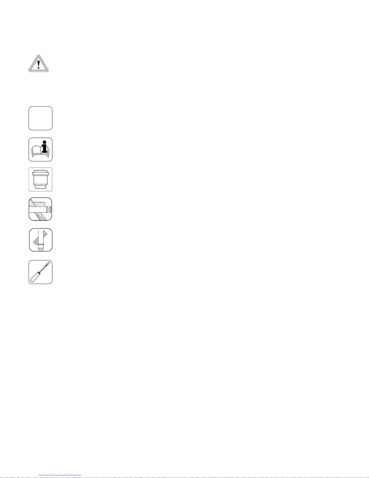
Fig. 1.1: Extensions, Ø 60/100
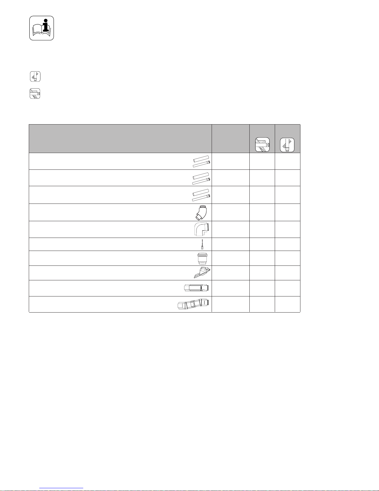
Fig. 1.3: Flue support clips, Ø 100/Ø 80
Flue support clips, Ø 100 (pack of 5)
Vaillant Accy. No.: 303 921
☞ Use one clip per extension to
support the air/flue duct.
18
27
18
27
18
27
Fig. 1.2: Elbow joints, Ø 60/100
Elbow, 87°, Ø 60/100
Vaillant Accy. No.: 303 910
Bends, 45° (pack of 2),
Ø 60/100
Vaillant Accy. No.: 303 911
Air/flue duct extension 470 mm
Ø 60/100
Vaillant Accy. No.: 303 902
Air/flue duct extension 970 mm,
Ø 60/100
Vaillant Accy. No.: 303 903
Air/flue duct extension 1970 mm,
Ø 60/100
Vaillant Accy. No.: 303 905
GU_LAZ 70/0
GU_LAZ 72/0
440 – 690
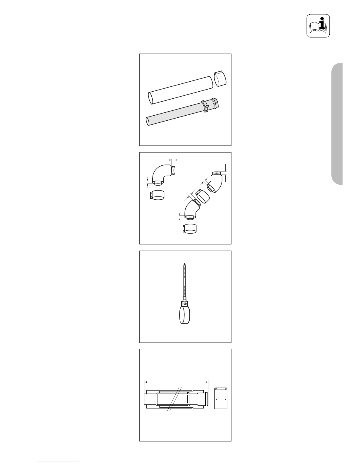
Fig. 1.4: Telescopic extension, Ø 60/100
Telescopic extension (PP), Ø 60/100
440 mm - 690 mm
Vaillant Accy. No.: 303 906
Page 8
8
PLANNING THE AIR/FLUE DUCT LAYOUT
155
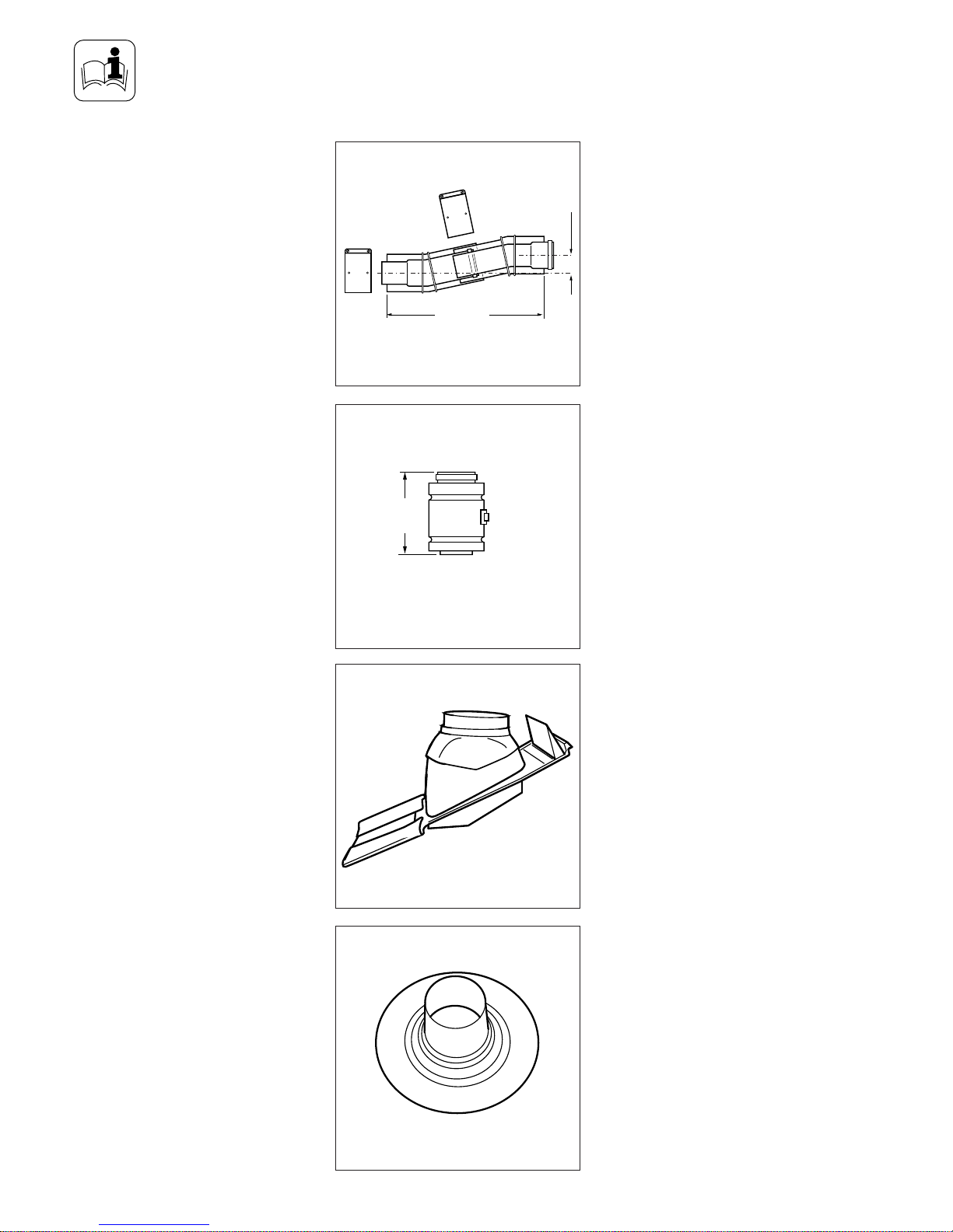
Fig. 1.6: Sliding sleeve, Ø 60/100
Sliding sleeve (PP), Ø 60/100
Vaillant Accy. No.: 303 915
290 – 374
33 – 56
Fig. 1.5: Offset section, Ø 60/100
Offset section, Ø 60/100
Vaillant Accy. No.: 303 919
303919_IAx
Fig. 1.8: Flat roof penetration collar
GU_LAZ 42/0
Flat roof penetration collar
Vaillant Accy. No.: 009 056
Fig. 1.7: Adjustable roof tile for pitched roof
Adjustable roof tile for pitched roof
Vaillant Accy. No.: 009 076 (black)
GU_LAZ 41/0
Page 9
9
PART 1 CONCENTRIC 60/100
PLANNING THE AIR/FLUE DUCT LAYOUT
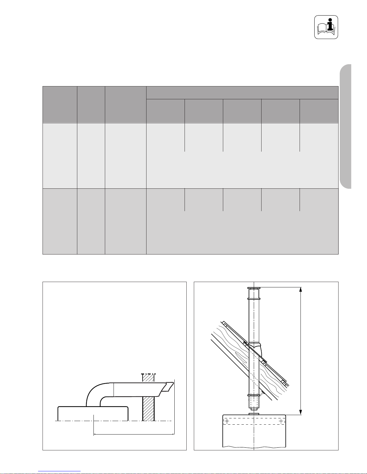
Maximum flue lengths for use with ecoMAX
Maximum flue length
Maximum flue length
LAS Euro B/S 074/0
LAS Euro B/S 074/0
Fig. 1.5
Fig. 1.6
Accessories Accy. No.
Vertical
flue systems
303 900
Max. permitted
concentric
flue length
Horizontal
flue systems
303 930 Max. permitted
concentric
flue length
12.0 m
8.0 m
incl.
1 elbow 87°
828/2 E 835/2 E pro 18 E
pro 28 E
10.0 m 7.0 m 10.0 m
8.0 m
incl.
1 elbow 87°
4.0 m
incl.
1 elbow 87°
10.0 m
incl.
1 elbow 87°
824/2 E
9.0 m
7.0 m
incl.
1 elbow 87°
613/2 E
618/2 E
622/2 E
ecoMAX
of which no more than 5 m lie in exposed position.
Maximum length of flue is reduced by 1.0 m for each additional 90° elbow
Maximum length of flue is reduced by 0.5 m for each additional 45° elbow
of which no more than 5 m lie in exposed position.
Maximum length of flue is reduced by 1.0 m for each additional 90° elbow
Maximum length of flue is reduced by 0.5 m for each additional 45° elbow
Page 10
10
INSTALLING THE AIR/FLUE DUCT SLIDING SLEEVE
Fig. 2.0: Installing the sliding sleeve
1
2
3 1 24
567
Schiebemuffe_neu
INSTALLING THE
AIR/FLUE DUCT SLIDING
SLEEVE
☞ NOTE:
For installations where there is insufficient movement to allow fitting
of the flue into flue outlet, a sliding sleeve (Accy. No. 303 915) is
available. When using the sliding
sleeve both the air and flue ducts
of the last extension must be
shortened by a further 95 mm.
• Push the sliding sleeve (1) over the
cut end of the flue duct (2).
• Place the air duct clamp (7) over
the air duct.
• Pull back the sliding sleeve so that
it engages into the socket (3) of
the boiler (4). Ensure that the
sliding sleeve penetrates the
socket such that there is at least
20 mm engagement at both ends
of the sliding sleeve.
• Fit the air duct clamp over the air
ducts (5 and 6) of the
extension/terminal and boiler
outlet. Close the snap clamp.
• Drill two holes 3 mm diameter
through the air duct clamp (the
centre of the holes should be 6
mm from the edge of the clamp).
Ensure that the drill does not
penetrate the inner flue duct.
Screw the air duct clamp to the
air duct of the sleeve using the
screws provided.
• Complete the installation of the
flue as detailed in these
instructions.
Page 11
11
800
☞ Observe the maximum flue
lengths as detailed in table on
page 9
Horizontal air/flue duct
Vaillant Accy No.: 303 930
Contents of the accessory:
• Horizontal air/flue duct
• 87° elbow
• 1 x 70 mm air duct clamp
• 1 x 40 mm air duct clamp
• Internal trim ring Ø 100
• External wall seal
☞See page 6 et seq. for details of
air/flue duct elements.
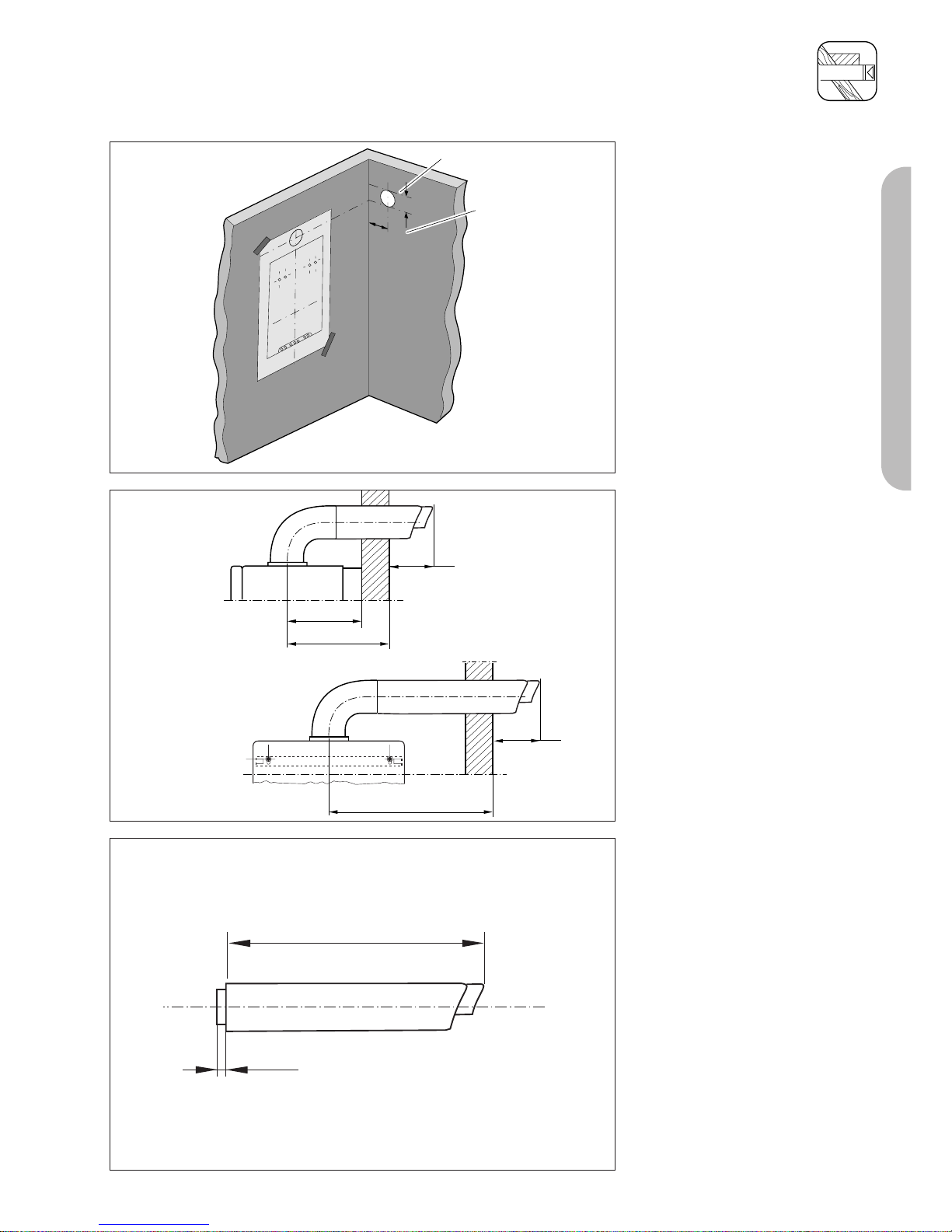
Fig. 3.0: Horizontal air/flue conduit
Important:
The flue hole should be cut with a
slight rise to outside of 3°± 1°
(equivalent to 50 mm ± 20 mm rise
per metre length).
INSTALLATION OF THE HORIZONTAL AIR/FLUE DUCT
PART 1 CONCENTRIC 60/100
Page 12
12
INSTALLATION OF THE HORIZONTAL AIR/FLUE DUCT
Horizontal air/flue duct
Accy No.: 303 930
(Length 0.8 m)
Contents of the accessory:
• Horizontal air/flue duct
• 87° elbow
• 2 x 70 mm air duct clamps
• 1 x 40 mm air duct clamp
• Internal trim ring Ø 100
• External wall seal.
Fig. 3.1: Horizontal air/flue conduit
IMPORTANT:
The flue hole should be cut with a
slight rise to outside if 3° ± 1°
(equivalent to 50 mm ± 20 mm rise
per metre length).
Preparation
• Determine the installation site for
the boiler with reference to the
installation and servicing
instructions supplied with the
boiler.
• Ensure that all installation and
service clearances are available
and that the boiler flue can be
installed as detailed in these
instructions.
• Fix the paper template, supplied
with the boiler, to the wall
ensuring that the centreline of the
template is vertical using a
plumbline or spirit level.
Top outlet flue exiting to rear
• For installations where the air/flue
duct is to be installed directly to
the rear of the boiler, the
installation template details the
position of the flue exit hole for
horizontal top outlet installation.
Top outlet flue exiting to side
• For installations where the air/flue
duct is to be installed to the side,
the position of the flue exit hole
can be determined by carefully
levelling across the wall from the
centre line of the air/flue duct
hole marked on the template.
• The position of the flue exit hole
should allow the flue to be
installed with a slight upward
slope of about 3° ± 1° (equivalent
to 50 mm ± 20 mm per metre of
flue duct). Calculate the required
rise according to the flue length
and mark the position of the flue
exit hole.
800
40
13
70
LAS Euro B/S 037/0
5
190 150
6
6
2
3
Fig. 3.1a
LAS Euro B/S 072/0GB
*
* = 190 mm ecoMAX
combination and system boilers
* = 176 mm ecoMAX pro
Page 13
13
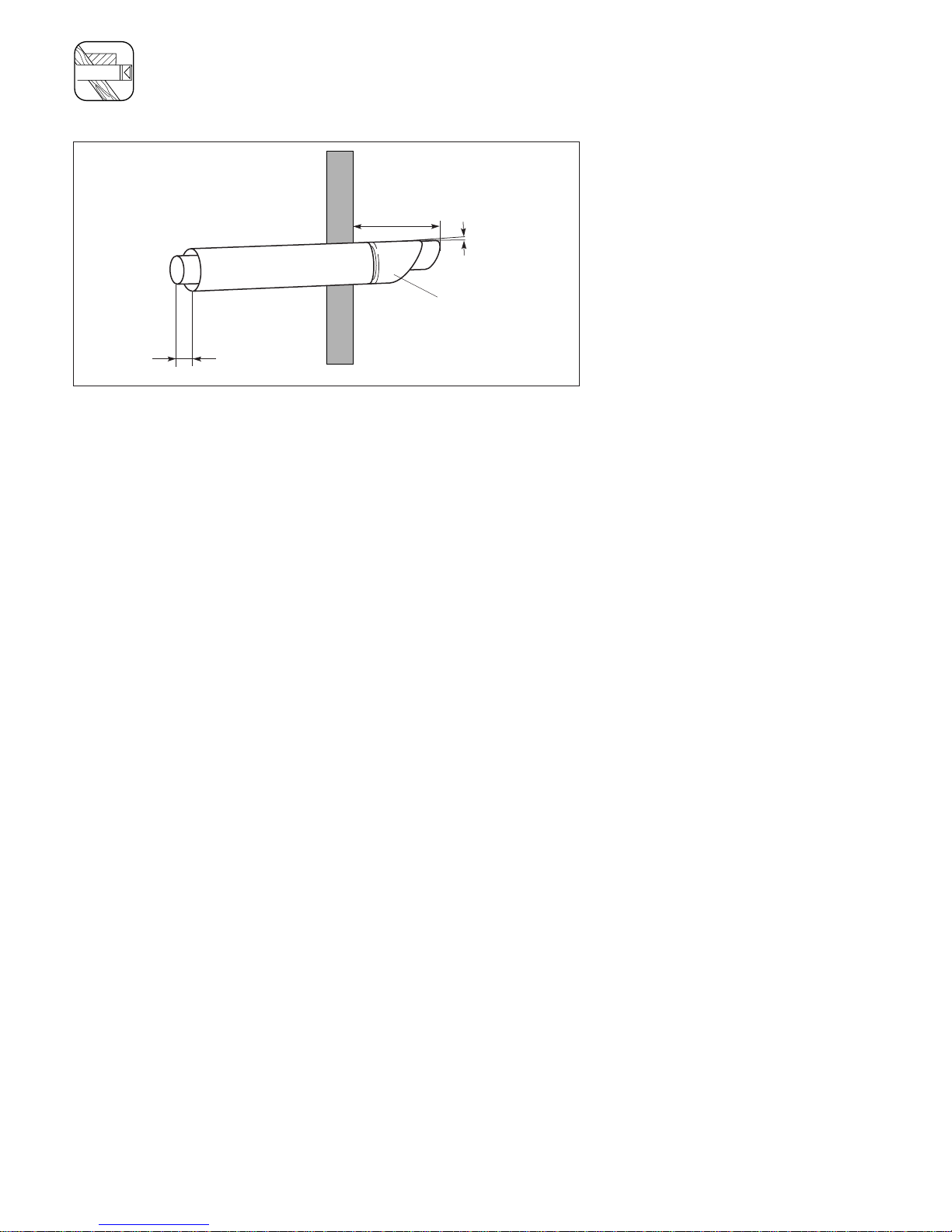
INSTALLATION OF THE HORIZONTAL AIR/FLUE DUCT (TOP OUTLET)
• Once the position of the flue exit
hole has been determined, the
hole should be cut through the
wall using a core drill of 125 mm
diameter.
Note: If access can be gained to
the proposed flue exit point from
outside the dwelling, the hole can
be cut with a 107 mm core drill
and the flue external wall seal
fitted from outside the dwelling.
• Measure the distance from the
outside face of the wall to the
centre of the fan outlet on the
boiler.
This is dimension A.
• Cut the air duct and flue duct to
the lengths shown in figure 3.4.
• All flue sockets should point
towards the terminal.
• When cutting the air and flue
ducts it is important to remove any
burrs with a file, this ensures easy
fitting of the ducts and prevents
any rough edges from damaging
the flue seals.
Care should be taken not to
scratch the white surface of the air
duct.
• If the installation requires the use
of air/flue duct extensions,
additional bends or elbows refer
to the sections on pages 20 – 21.
• Secure the air duct sections
together by drilling a 3 mm
diameter hole through the location
hole in the end of the outer air
duct. (Ensure that the drill does
not pierce the inner flue duct).
Secure the air ducts together using
the screw
provided.
1
2
*
* = 190 mm
Fig. 3.2
LAS Euro B/S 077/1
150
A
B
A
150
Fig. 3.3
LAS Euro B/S 078/0
A + 45 mm
13 mm
Fig. 3.4
LAS Euro B/S 076/0
Rear exit
Side exit
PART 1 CONCENTRIC 60/100
*
* = 190 mm ecoMAX
combination and system boilers
* = 176 mm ecoMAX pro
* = 190 mm ecoMAX combination and system boilers
* = 176 mm ecoMAX 400
Page 14
14
INSTALLATION OF THE HORIZONTAL AIR/FLUE DUCT (TOP OUTLET)
• Push the air/flue duct assembly
(1) including the flexible external
seal (2) through the wall until the
seal clears the outside face of the
wall and pull air/flue duct back
towards the boiler until the
external seal touches the outside
wall.
• Ensure that the air/flue duct (1) is
centred in the hole and the
terminal is correctly positioned
with the inlet grille at the bottom.
• Slide the internal trim ring (3) over
the air duct until it is flush with the
wall.
• At this stage it is necessary to
prepare and fit the boiler onto the
hanging bracket – refer to the
boiler installation instructions.
• Fit the elbow to the boiler by
inserting the spigot of the flue
elbow into the flue socket on the
boiler and secure using the air
duct clamp provided.
• Pull the air/flue duct back through
the wall such that the flue duct
fully engages into the flue elbow
socket.
• Fit the air duct clamp ensuring
that it is positioned centrally.
• Drill two holes 3 mm Ø through
the air duct of both the elbow/flue
and elbow/boiler clamps at the
most convienient holes on the air
duct clamps. (Ensure that the drill
does not penetrate the inner flue
duct). Screw the clamps to the air
ducts of the flue assembly, the
elbow and boiler using the
screws supplied.
• Slide the internal trim ring back to
the wall, securing in position with
a small amount of sealant if
required.
150
13
3°
1
Fig. 3.5
LAS Euro B/S 001/0GB
Page 15

15
PART 1 CONCENTRIC 60/100
1530
880
70
Vertical air/flue duct
Accy. Vaillant Part No.: 303 900
(black)
Contents of the accessory:
• Vertical air/flue duct and terminal
assembly
• 70 mm air duct clamp
• Fixing bracket
☞See page 6 et seq. for details of
air/flue duct elements.
☞ Observe the maximum flue
lengths as detailed in table on
page 9
Fig. 4.1: Vertical roof duct
The air/flue duct assembly may be
connected directly to the flue outlet
on top of the boiler.
In addition to the vertical air/flue
duct and terminal accessory, air/flue
duct extensions can be added to
increase the length of the flue.
Preparation
• Determine the installation site for
the boiler with reference to the
installation and servicing
instructions supplied with the
boiler.
• Ensure that all installation and
service clearances are available
and that the boiler flue can be
installed as detailed in these
instructions.
• Determine the point where the
vertical air/flue duct and terminal
assembly will penetrate the roof.
☞ Please note: The vertical air/flue
duct and terminal accessory
(Accy. No. 303 900) may be
shortened. The outer ‘white’ duct
should be shortened first, then the
inner flue duct cut so that it
protrudes 13 mm out of the air
duct. In case of installation
directly to the boiler without
elbows or bends, it is essential
that the roof tile/collar is vertically
aligned with the air/flue duct of
the boiler.
INSTALLATION OF THE VERTICAL AIR/FLUE DUCT
Page 16

16
INSTALLATION OF THE VERTICAL AIR/FLUE DUCT
Pitched roof installation
• Determine the point where the
vertical air/flue duct and terminal
assembly will penetrate the roof.
• Fit the adjustable pitched roof tile
(1).
• Working from above, insert the
vertical roof duct (5) through the
roofing tile and push it firmly into
place.
• Vertically align the roof duct and
attach it to the roof structure with
the fixing bracket (6) supplied.
• Fit the boiler hanging bracket (2).
• Install the appliance (3) with
reference to the installation and
servicing instructions supplied with
the boiler.
☞ See pages 18 et seq. for further
details on the installation of
extensions and elbows.
• Push the sliding sleeve (4) firmly
into place on the extension.
• Join the vertical roof duct (5) to
the extension (7).
• Join the sliding sleeve (4) to the
appliance’s connection piece (8).
This permits easy separation
between the air/flue duct and the
appliance.
• Drill two holes 3 mm Ø through
the air duct of the flue/boiler
clamp at the most convienient
holes on the air duct clamp.
(Ensure that the drill does not
penetrate the inner flue duct).
Screw the clamp to the air ducts
of the flue assembly and the boiler
using the screws supplied.
• Ensure that any air duct clamps
used are positioned centrally and
fixed to the air duct using the self
tapping screws supplied.
• Note: The air/duct clamp must not
be screwed to the bottom of the
vertical air/flue duct and terminal
accessory to allow for any slight
movement in the roof structure.
• Ensure that at least one pipe
clamp supports the air/flue duct
at each extension fitted.
750
2
3
790
740
Ø100
20 – 50°
4
5
6
40
8
0 – 20
190
7
8
1
Fig. 4.2: Fitting the appliance and the vertical roof duct to a building with a pitched roof
*
* = 190 mm ecoMAX
combination and system boilers
* = 176 mm ecoMAX pro
750 mm ecoMAX
combination and system boilers
530 mm ecoMAX pro
(top holes of bracket)
Page 17

17
INSTALLATION OF THE VERTICAL AIR/FLUE DUCT
PART 1 CONCENTRIC 60/100
880
warm roof
cold roof
650
Ø100
≥120
2
1
5
6
7
750
4
40
7
Fig. 4.4: Fitting the appliance and vertical flue duct to a building with a flat roof
Flat-roof installation
• Determine the point where the
vertical air/flue duct and terminal
assembly will penetrate the roof.
• Fit the flat roof penetration collar
(1).
• Stick the flat roof penetration
collar firmly into place with
adhesive in accordance with the
codes of practice for flat roofs
(CP 144) to ensure a watertight
seal.
• Working from above, insert the
vertical roof duct (5) through the
flat roof collar and push it firmly
into place.
• Vertically align the roof duct and
attach it to the roof structure with
the fixing bracket (6) supplied.
• Fit the boiler hanging bracket (2).
• Install the appliance (3) with
reference to the installation and
servicing instructions supplied with
the boiler.
☞ See pages 19 et seq. for further
details on the installation of
extensions and elbows.
• Push the sliding sleeve (4) firmly
into place on the extensionn.
• Join the vertical roof duct (5) to
the extension (7).
• Join the sliding sleeve (4) to the
appliance’s connection piece (8).
This permits easy separation
between the air/flue duct and the
appliance.
• Drill two holes 3 mm Ø through
the air duct of the flue/boiler
clamp at the most convienient
holes on the air duct clamp.
(Ensure that the drill does not
penetrate the inner flue duct).
Screw the clamp to the air ducts
of the flue assembly and the boiler
using the screws supplied.
• Ensure that any air duct clamps
used are positioned centrally and
fixed to the air duct using the self
tapping screws supplied.
• Note: The air/duct clamp must not
be screwed to the bottom of the
vertical air/flue duct and terminal
accessory to allow for any slight
movement in the roof structure.
• Ensure that at least one pipe
clamp supports the air/flue duct
at each extension fitted.
750 mm ecoMAX
combination and system boilers
530 mm ecoMAX pro
(top holes of bracket)
Page 18

18
FITTING AIR/FLUE DUCT EXTENSIONS
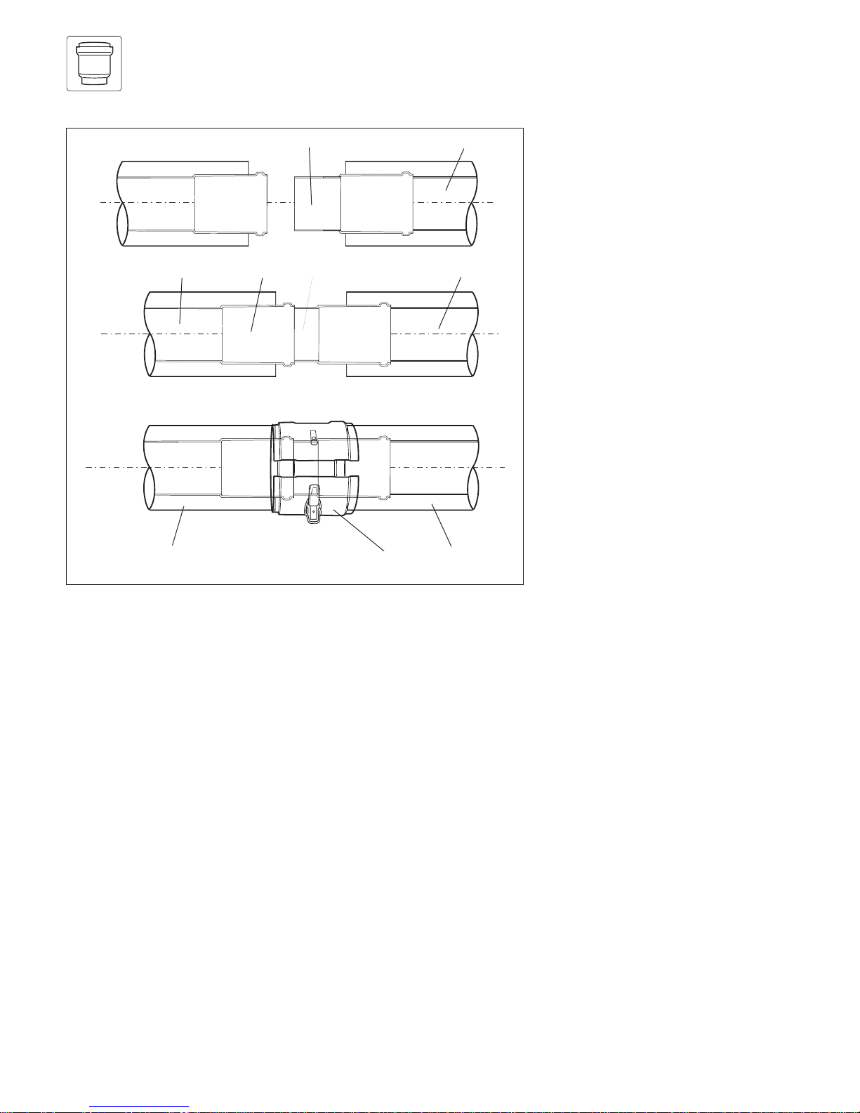
How to add extensions
Use a saw, tin-snips, etc. to cut tubes
to size.
☞ No tools are required when
separating extensions for cutting to
size air and flue tubes separately.
When doing so, the flue conduit
should be twisted into a position
where the shoulders on the plastic
tube can be pushed through the
spacer-piece. After cutting to size,
refit the flue conduit and secure it
to the air conduit.
Tip:
Start by measuring the required
length of air conduit* (L
air
), and then
calculate the corresponding length of
flue conduit (L
exhaust
) as follows:
L
exhaust
= L
air
+ 40 mm
L
exhaust
= length of flue conduit
L
air
= length of air conduit
* Minimum length of air-conduit
extension: 80 mm.
1
2
13
2
70
L
air
L
exhaust
1.
2.
+ 40 mm
27
1
Fig. 9.1: Cutting tubes to size
☞ The seals are sensitive to mineral
oil-based grease products. For this
reason, the seals must not be
greased. If the seals need wetting
to aid in installation, use water
only.
☞ De-burr and file down any rough
edges on the tubes before fitting in
order to prevent damage to the
seals. Remove all metal filings and
other debris.
☞ Do not use damaged or dented
tubes, as they will not form an
adequate seal.
☞ Ensure that the seals remain
correctly aligned when installing
the tubes. Do not fit damaged
seals.
☞ Secure the exhaust conduit with
the fixing device in order to ensure
that it is correctly centred relative
to the air conduit.
Fig. 9.2: Loosening the flue conduit
GU_LAZ 290/1
Page 19

19
PART 1 CONCENTRIC 60/100
FITTING AIR/FLUE DUCT EXTENSIONS
Offset Length of
[in mm] air conduit
[in mm
]
Offset Length of
[in mm] air conduit
[in mm
]
Offset Length of
[in mm] air conduit
[in mm
]
690 480
695 485
700 490
705 495
710 500
715 505
720 510
725 515
730 520
735 525
740 530
745 535
750 540
755 545
760 550
765 555
770 560
775 565
780 570
785 575
790 580
795 585
800 590
470 260
475 265
480 270
485 275
490 280
495 285
500 290
505 295
510 300
515 305
520 310
525 315
530 320
535 325
540 330
545 335
550 340
555 345
560 350
565 355
570 360
575 365
580 370
585 375
590 380
595 385
600 390
605 395
610 400
615 405
620 410
625 415
630 420
635 425
640 430
645 435
650 440
655 445
660 450
665 455
670 460
675 465
680 470
685 475
Table 10.1: Length of surplus with 87° elbows
> 190 to
< 210 mm 0
> 215 to not
< 265 mm possible
> 270 to
< 290 mm 80
295 85
300 90
305 95
310 100
315 105
320 110
325 115
330 120
335 125
340 130
345 135
350 140
355 145
360 150
365 155
370 160
375 165
380 170
385 175
390 180
395 185
400 190
405 195
410 200
415 205
420 210
425 215
430 220
435 225
440 230
445 235
450 240
455 245
460 250
465 255
How to install elbows
Example:
An offset of 400 mm is measured.
This value is then used, along with the
table below, to determine the length
of the air conduit ( = 190 mm in this
case).
Important:
This gives a corresponding
exhaust-conduit length of
190 + 40 = 230 mm.
(cf. page 19)
Fig. 10.1: Installation of 87° elbows
190
Offset
Lenght of air conduit
95
95
10
10
GU_LAZ 102/2GB
Page 20

20
FITTING AIR/FLUE DUCT EXTENSIONS
90 0 210
95 0 215
100 0 220
> 105 to not
< 155 mm possible
160 86 280
165 93 285
170 100 290
175 107 295
180 115 300
185 122 305
190 129 310
195 136 315
200 143 320
205 150 325
210 157 330
215 164 335
220 171 340
225 178 345
230 185 350
235 192 355
240 199 360
245 206 365
250 214 370
255 221 375
260 228 380
265 235 385
270 242 390
275 249 395
280 256 400
285 263 405
290 270 410
295 277 415
300 284 420
305 291 425
310 298 430
315 306 435
320 313 440
Offset Length of Height
[in mm] air conduit [in mm]
[in mm]
Offset Length of Height
[in mm] air conduit [in mm]
[in mm]
Table 10.2: Length of surplus with 45° bends
Offset Length of Height
[in mm] air conduit [in mm]
[in mm]
How to install elbows
Example:
An offset of 400 mm is measured.
This value is then used, along with the
table below, to determine the length
of the air conduit (= 284 mm) and the
height (= 420 mm).
Important:
This gives a corresponding
exhaust-conduit length of
284 + 40 = 324 mm.
(cf. page 19)
GU_LAZ 103/2GB
Fig. 10.2: Installation of 45° bends
325 320 445
330 327 450
335 334 455
340 341 460
345 348 465
350 355 470
355 362 475
360 369 480
365 376 485
370 383 490
375 390 495
380 397 500
385 404 505
390 412 510
395 419 515
400 426 520
405 433 525
410 440 530
415 447 535
420 454 540
425 461 545
430 468 550
435 475 555
440 482 560
445 489 565
450 496 570
455 503 575
460 511 580
465 518 585
470 525 590
475 532 595
480 539 600
485 546 605
490 553 610
495 560 615
500 567 620
505 574 625
510 581 630
515 588 635
520 595 640
525 602 645
530 610 650
535 617 655
540 624 660
545 631 665
550 638 670
555 645 675
560 652 680
565 659 685
570 666 690
575 673 695
580 680 700
585 687 705
590 694 710
595 701 715
600 709 720
605 716 725
610 723 730
615 730 735
620 737 740
625 744 745
630 751 750
635 758 755
640 765 760
645 772 765
650 779 770
655 786 775
660 793 780
665 800 785
670 808 790
675 815 795
680 822 800
Height
Offset
Lenght of air conduit
10
10
Page 21

21
CONTENTS: PART 2 CONCENTRIC 80/125
Page
The air/flue duct must be installed by a suitably
qualified service provider, which is responsible
for observing the relevant specifications,
regulations and standards.
Requirements
Planning the air/flue duct
layout
Regulations and standards to be observed 22
Alternative termination accessories available 23
Maximum flue lengths 26
Changing the appliance
connection piece
§
28
Installation of the vertical air/flue duct
35
Installation of the horizontal air/flue duct
30
Fitting air/flue duct extensions
Installation of the sliding sleeve
How to add extensions 38
How to install elbows 39
29
Page 22

22
REQUIREMENTS
Regulations and
standards to be
observed
§
☞ Vaillant ecoMAX boilers are
certified as heating boilers with
corresponding flue systems
according to EC Directive
90/396/EEC on gas-fired
devices. This installation manual is
covered by this certification and is
referred to in the design approval
test certificate.
☞ These instructions should be read
in conjunction with the instructions
for installation and servicing
supplied with the boiler.
☞ Ensure also that all legislation,
rules, regulations and directives
mentioned in the installation
instructions are observed.
☞ The installation of the boiler and
its flue must be carried out by a
competent person who is
registered with CORGI (The
Council for Registered Gas
Installers).
☞ The installation of the boiler and
flue must be in accordance with
the Gas Safety (Installation and
Use) Regulations 1998 and the
Building Regulations and
BS 5440 Part 1.
☞ The requirements for flue
termination detailed in the boiler
installation instructions must be
observed.
☞ The air/flue duct operates at very
low temperatures therefore no
clearance is necessary between
the air duct and adjacent
services.
☞ Ensure while installation work is
being carried out that no debris
such as swarf, filings or fragments
of mortar are allowed to remain
in the air/flue duct.
Page 23

23
PART 2 CONCENTRIC 80/125
PLANNING THE AIR/FLUE DUCT LAYOUT
Alternative termination
accessories available
303 200 = Vertical air/flue duct (black)
303 209 = Horizontal air/flue duct
303 907 = Appliance connection piece
Optional connection accessories Accy. No.
303 200
Air/flue duct extensions (PPs), concentric
470 mm - Ø 80/125
303 202 x
Air/flue duct extensions (PPs), concentric
970 mm - Ø 80/125
303 203 x
Air/flue duct extensions (PPs), concentric
1970 mm - Ø 80/125
303 205 x
Bends (PPs), concentric (pack of 2)
45° - Ø 80/125
303 211 x
Elbow (PPs), concentric
87° - Ø 80/125
303 210 x
Flue support clips (pack of 5), Ø 125 303 616 x
Sliding sleeve (PPs) Ø 80/125 303 215 x
Adjustable roof tiles for pitched roof
009076 black
x
Flat roof penetration collar 009 056 x
303 209
x
x
x
x
x
x
x
x
x
Page 24

24
PLANNING THE AIR/FLUE DUCT LAYOUT
Fig. 1.2: Extensions, Ø 80/125
Fig. 1.4: Flue support clips, Ø 125 or Ø 80
Flue support clips, Ø 125 (pack of 5)
Vaillant Accy. No.: 303 616
☞ Use one clip per extension to
support the air/flue duct.
15
25
15
25
15
25
Fig. 1.3: Elbow joints, Ø 80/125
Elbow (PPs), 87°, Ø 80/125
Vaillant Accy. No.: 303 210
Bends (PPs), 45° (pack of 2),
Ø 80/125
Vaillant Accy. No.: 303 211
Air/flue duct extension (PPs) 470 mm,
Ø 80/125
Vaillant Accy. No.: 303 202
Air/flue duct extension (PPs) 970 mm,
Ø 80/125
Vaillant Accy. No.: 303 203
Air/flue duct extension (PPs) 1970 mm,
Ø 80/125
Vaillant Accy. No.: 303 205
GU_LAZ 70/0
GU_LAZ 72/0
GU_LAZ 71/0
58
25
15,5
Fig. 1.1: Appliance connection piece
Appliance connection piece
Ø 80/125
Vaillant Accy. No.: 303 907
(with 2 measuring apetures)
Page 25

25
PART 2 CONCENTRIC 80/125
PLANNING THE AIR/FLUE DUCT LAYOUT
Fig. 1.6: Adjustable roof tile for pitched roof
Adjustable roof tiles for pitched roof
Vaillant Accy. No.: 009 076 (black)
GU_LAZ 41/0
164
120
Fig. 1.5: Sliding sleeve, Ø 80/125
Sliding sleeve (PPs), Ø 80/125
Vaillant Accy. No.: 303 215
GU_LAZ 76/0
Fig. 1.7: Flat roof penetration collar
GU_LAZ 42/0
Flat roof penetration collar
Vaillant Accy. No.: 009 056
Page 26

26
PLANNING THE AIR/FLUE DUCT LAYOUT
Maximum flue lengths for use with ecoMAX
Accessories Accy. No.
Vertical
flue systems
303 200
Max. permitted
concentric
flue length
Horizontal
flue systems
303 209 Max. permitted
concentric
flue length
14.0 m
13.0 m
incl.
1 elbow 87°
31.0 m
20.0 m
30.0 m
incl.
1 elbow 87°
20.0 m
incl.
1 elbow 87°
27.0 m
25.0 m
incl.
1 elbow 87°
613/2 E 618/2 E 622/2 E pro 18 E
pro 28 E
ecoMAX
of which no more than 5 m lie in exposed position.
Maximum length of flue is reduced by 2.5 m for each additional 90° elbow.
Maximum length of flue is reduced by 1.0 m for each additional 45° elbow.
of which no more than 5 m lie in exposed position.
Maximum length of flue is reduced by 2.0 m for each additional 90° elbow
Maximum length of flue is reduced by 1.0 m for each additional 45° elbow
Accessories Accy. No.
Vertical
flue systems
303 200
Max. permitted
concentric
flue length
Horizontal
flue systems
303 209 Max. permitted
concentric
flue length
26.0 m
25.0 m
incl.
1 elbow 87°
22.0 m
21.0 m
incl.
1 elbow 87°
29.0 m
30.0 m
incl.
1 elbow 87°
824/2 E 828/2 E 835/2 E
ecoMAX
of which no more than 5 m lie in exposed position.
Maximum length of flue is reduced by 2.5 m for each additional 87° elbow.
Maximum length of flue is reduced by 1.0 m for each additional 45° elbow.
of which no more than 5 m lie in exposed position.
Maximum length of flue is reduced by 2.5 m for each additional 90° elbow
Maximum length of flue is reduced by 1.0 m for each additional 45° elbow
Page 27

27
PART 2 CONCENTRIC 80/125
PLANNING THE AIR/FLUE DUCT LAYOUT
Maximum flue length
Maximum flue length
LAS Euro B/S 074/0
LAS Euro B/S 074/0
Fig. 1.9
Fig. 1.8
Page 28

28
CHANGING THE APPLIANCE CONNECTION-PIECE
1
2
Fig. 2.0: Fitting the appliance connection-piece
Installation
The appliance is supplied ready-fitted
with the connection-piece for the
60/100 air/flue duct system.
• Loosen the four screws (2) and
pull the appliance connectionpiece (1) upwards to remove it.
• Push the appliance connectionpiece with the selected connection
diameter down from above,
inserting the push-in end onto the
sleeve of the flue collecting
chamber. Now push the
appliance connection-piece
downwards until the flange comes
into contact with the low-pressure
chamber.
• Refit the fixing screws (2).
The seals are sensitive to
mineral oil-based grease
products.
For this reason, the seals must
not be greased. If the seals
need wetting to aid in
installation, use water only.
Page 29

29
PART 2 CONCENTRIC 80/125
INSTALLATION OF THE SLIDING SLEEVE
Fig. 3.0: Installing the sliding sleeve
1
2
3 1 24
567
Schiebemuffe_neu
INSTALLING THE
AIR/FLUE DUCT SLIDING
SLEEVE
☞ NOTE:
For installations where there is insufficient movement to allow fitting
of the flue into flue outlet, a sliding sleeve (Accy. No. 303 215) is
available. When using the sliding
sleeve both the air and flue ducts
of the last extension must be
shortened by a further 85 mm.
• Push the sliding sleeve (1) over the
cut end of the flue duct (2).
• Place the air duct clamp (7) over
the air duct.
• Pull back the sliding sleeve so that
it engages into the socket (3) of
the boiler (4). Ensure that the
sliding sleeve penetrates the
socket such that there is at least
20 mm engagement at both ends
of the sliding sleeve.
• Fit the air duct clamp over the air
ducts (5 and 6) of the
extension/terminal and boiler
outlet. Close the snap clamp.
• Drill two holes 3 mm diameter
through the air duct clamp (the
centre of the holes should be 6
mm from the edge of the clamp).
Ensure that the drill does not
penetrate the inner flue duct.
Screw the air duct clamp to the
air duct of the sleeve using the
screws provided.
• Complete the installation of the
flue as detailed in these
instructions.
Page 30

30
INSTALLATION OF THE HORIZONTAL AIR/FLUE DUCT
☞ Observe the maximum flue
lengths as detailed in table on
page 27
70
1103
70
15
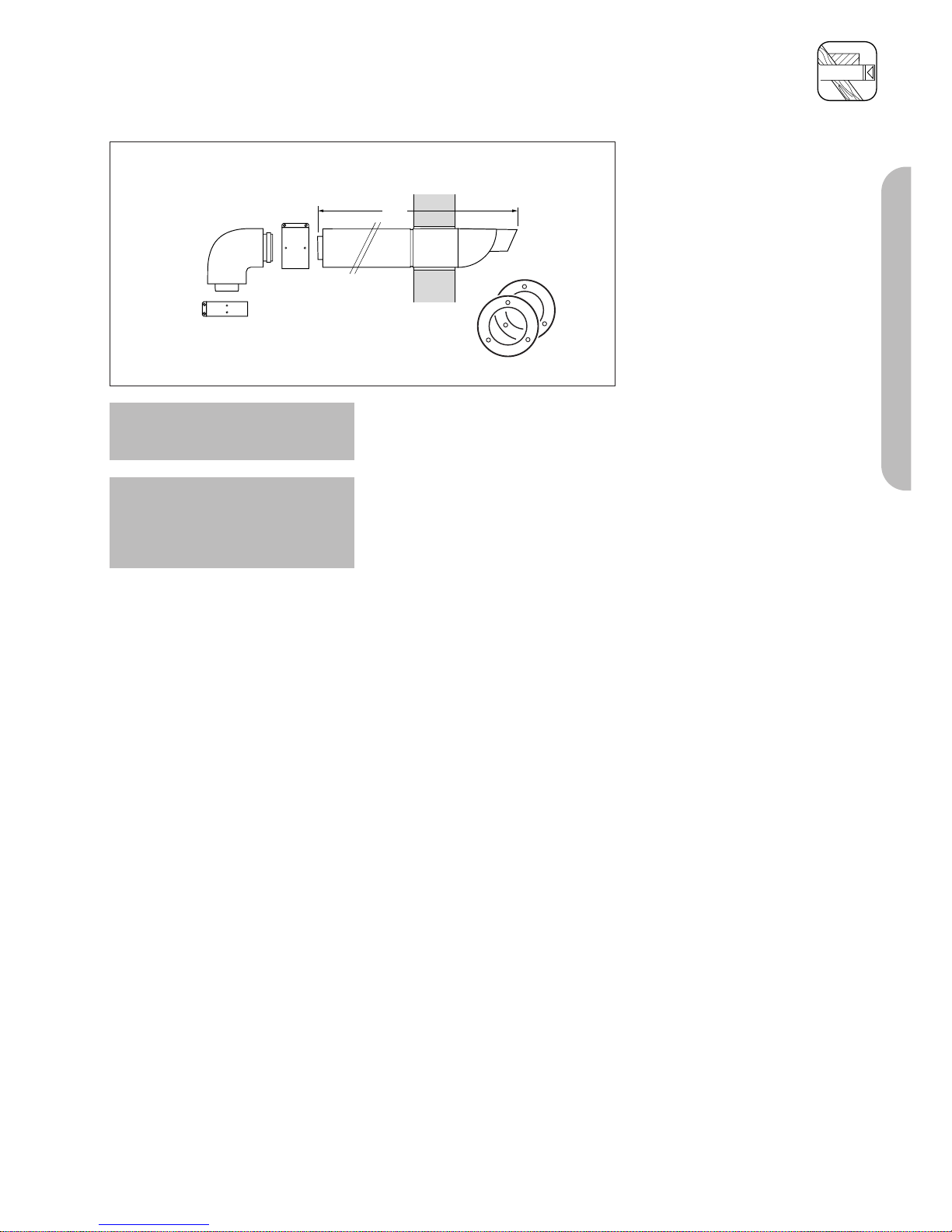
Horizontal air/flue duct
Vaillant Accy No.: 303 209
Contents of the accessory:
• Horizontal air/flue duct
• 87° elbow
• 2 x 70 mm air duct clamps
• 2 x internal trim rings Ø 125
☞See page 24 et seq. for details of
air/flue duct elements.
Fig. 4.1: Horizontal air/flue conduit
GU_LAZ 82/0
Important:
The flue hole should be cut with a
slight rise to outside of 3° ± 1°
(equivalent to 50 mm ± 20 mm rise
per metre length).
Fig. 4.2: Example of installation with horizontal air/flue duct and
inspection-access T-piece
Page 31

31
PART 2 CONCENTRIC 80/125
IMPORTANT:
The flue hole should be cut with a
slight rise to outside of 3° ± 1°
(equivalent to 50 mm ± 20 mm rise
per metre length).
Side flue installations
• For installations where the air/flue
duct is to be installed to the side,
the position of the flue exit hole
can be determined as follows:
• Identify the correct measurement
as shown in fig. 3.2, carefully
measure the distance from the
bottom centre of the boiler
hanging bracket (centreline of the
two lower hanging bracket fixing
holes). This gives the position of
the centreline of the 127 mm flue
elbow and adaptor when
installed.
• The position of the flue exit hole
can be determined by carefully
levelling across the wall from this
mark.
• The position of the flue exit hole
should allow the flue to be
installed with an upwards slope
towards the terminal of
approximately 3° ± 1°, equivalent
to 50 mm ± 20 mm rise per metre
of flue length. Calculate the
required rise according to the flue
length and mark the position of
the flue exithole.
Note: Due to the long lengths of flue
possible and the slope required, it
may be necessary to adjust the
location of the boiler installation
template. Please check that both the
boiler installation site and flue
termination are in accordance with
these instructions prior to drilling any
holes for the boiler hanging bracket.
• Once the position of the flue exit
hole has been determined, the
hole should be cut through the
wall using a core drill of 127 mm
diameter. The flue exit hole should
be cut with a rise towards outside
of 3°.
• Measure the distance from the
outside face of the wall to the
centre of the fan outlet on the
boiler (fig. 4.5).
This is dimension A.
• For installations where the
measured distance dimension A
(fig. 6) is greater than 960 mm,
an air/flue extension accessory
will be required. The number of
air/flue duct extensions which can
be used depends on the boiler.
Preparation
• Determine the installation site for
the boiler with reference to the
installation and servicing
instructions supplied with the
boiler.
• Ensure that all installation and
service clearances are available
and that the boiler flue can be
installed as detailed in these
instructions.
• Fix the paper template, supplied
with the boiler, to the wall
ensuring that the centreline of the
template is vertical using a
plumbline or spirit level.
1
2
*
* = 190 mm
Fig. 4.3
LAS Euro B/S 077/1
253
Fig. 4.4
LAS Euro B/S 083/1
INSTALLATION OF THE HORIZONTAL AIR/FLUE DUCT Ø 80/125 WITH
EXTENSIONS
* = 190 mm ecoMAX combination and system boilers
* = 176 mm ecoMAX pro
*
* = 253 mm ecoMAX
combination and system boilers
* = 210 mm ecoMAX pro
(from top holes on bracket)
Page 32

32
INSTALLATION OF THE HORIZONTAL AIR/FLUE DUCT Ø 80/125 WITH
EXTENSIONS
• Taking each extension to be used,
fit the flue duct into the air duct
and secure using the 3 screws
provided.
• For ease of measuring and
marking the air/flue duct
extensions, assemble them loosely
together with the air/flue duct and
terminal assembly as shown (fig.
4.6).
Note: The joints between the flue duct
sections are of a push-fit type, with
the flue duct spigot inserted into a
socket containing a sealing ring. For
ease of installation lubricate the seal
using soap solution prior to
assembling.
• Assemble the flue such that there
is a gap of about 10 mm between
each air duct, which will ensure
the correct flue duct penetration
into the flue sockets of 30 mm.
All flue sockets should point
towards the flue terminal.
• Measure from the flue terminal
and mark the air duct to a length
of:
Dimension A + 60 mm
• Take the extension(s) to be
shortened and remove the 3
screws. Separate the ducts.
Note: For assembly reasons do not
shorten any air duct to a length of
less than 100 mm. If necessary
shorten two adjacent extensions to
achieve the overall required length.
• Cut the air duct square and
remove any burrs.
• Refit the flue duct into the air duct
and secure using the 3 screws.
• Cut the flue duct as detailed in
fig. 4.7.
• When cutting the air and flue
ducts it is important to remove any
burrs with a file, this ensures easy
fitting of the ducts and prevents
any rough edges from damaging
the flue seals.
• Care should be taken not to
scratch the white surface of the air
duct.
• If the installation requires the use
of air/flue duct extensions,
additional bends or elbows refer
to the sections on pages 40 - 42.
• At this stage it is necessary to
prepare and fit the boiler onto the
hanging bracket – refer to the
boiler installation instructions.
• Fit the appliance flue outlet
adaptor to the boiler.
A
Fig. 4.5
LAS Euro B/S 082/0
10 mm
Mark air duct here
Dimension A + 20 mm
Fig. 4.6
LAS Euro B/S 084/0
25 mm
Mark flue duct here
15 mm
Fig. 4.7
LAS Euro B/S 080/0
Dimension A + 60 mm
Page 33

33
PART 2 CONCENTRIC 80/125
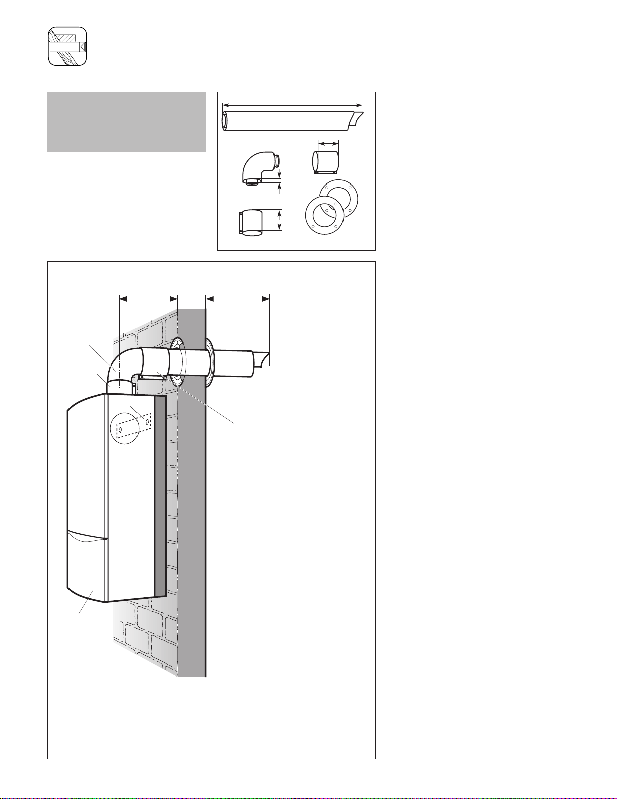
220
15
3°
1
Fig. 4.8: Installing the horizontal wall duct
LGU_LAZ 384/0_IT
• Push the assembled air/flue duct
and terminal assembly through the
flue exit hole until it protrudes
220 mm out from the outside
wall.
• Ensure that the terminal is
correctly positioned with the air
inlet grille at the bottom.
• Slide one of the two trim rings
over the air duct until it is flush
with the internal wall face.
INSTALLATION OF THE HORIZONTAL AIR/FLUE DUCT Ø 80/125 WITH
EXTENSIONS
Page 34

34
INSTALLATION OF THE HORIZONTAL AIR/FLUE DUCT AND TERMINAL
ACCESSORY (80/125 Ø)
8
82 - 84
253
7
4
2
3
6
750
Fig. 4.9: Indirect installation
Indirect installation
• Fit the wall mounting (2).
• Install the appliance (3) with
reference to the installation and
servicing instructions supplied with
the boiler.
• Change the appliance connectionpiece (7) as described on page
29.
• Join the 87° elbow (5) to the
appliance connection piece.
• Push the sliding sleeve (7) firmly
into place on the appropriate
extensionns (6).
• Install the extensions and join the
clutch sleeve to the 87° elbow.
☞ This section functions
subsequently as a separation
point.
• Join all separation points with the
air-conduit fixing collars (8).
☞ See pages 41 et seq. for further
details on the installation of
extensions and elbows.
**
*
* = 750 mm ecoMAX
combination and system boilers
* = 530 mm ecoMAX pro
(from top holes on bracket)
** = 253 mm ecoMAX
combination and system boilers
** = 210 mm ecoMAX pro
(from top holes on bracket)
Page 35

35
PART 2 CONCENTRIC 80/125
1530
880
70
Vertical air/flue duct
Accy. Vaillant Part No.: 303 200
(black)
Contents of the accessory:
• Vertical air/flue duct and terminal
assembly
• Adapter (air) for Ø 110/125
• 70 mm air duct clamp
• Fixing bracket
☞See page 24 et seq. for details of
air/flue duct elements.
☞ Observe the maximum flue
lengths as detailed in table on
page 27
Fig. 5.1: Vertical roof duct
GU_LAZ 81/0
The air/flue duct assembly may be
connected directly to the flue outlet
on top of the boiler.
In addition to the vertical air/flue
duct and terminal accessory, air/flue
duct extensions can be added to
increase the length of the flue.
Preparation
• Determine the installation site for
the boiler with reference to the
installation and servicing
instructions supplied with the
boiler.
• Ensure that all installation and
service clearances are available
and that the boiler flue can be
installed as detailed in these
instructions.
• Determine the point where the
vertical air/flue duct and terminal
assembly will penetrate the roof.
☞Please note: The vertical air/flue
duct and terminal accessory (Accy.
No. 303 200) may be shortened.
The outer ‘white’ duct should be
shortened first, then the inner flue
duct cut so that it protrudes 15 mm
out of the air duct. In case of
installation directly to the boiler
without elbows or bends, it is
essential that the roof tile/collar is
vertically aligned with the air/flue
duct of the boiler.
INSTALLATION OF THE VERTICAL AIR/FLUE DUCT
Page 36

36
INSTALLATION OF THE VERTICAL AIR/FLUE DUCT
750
2
3
790
740
Ø125
20 – 50°
4
5
6
40
10
8
190
7
1
8
Fig. 5.2: Fitting the appliance and the vertical roof duct to a building with a pitched roof
Pitched roof installation
• Determine the point where the
vertical air/flue duct and terminal
assembly will penetrate the roof.
• Fit the adjustable pitched roof tile
(1).
• Working from above, insert the
vertical roof duct (5) through the
roofing tile and push it firmly into
place.
• Vertically align the roof duct and
attach it to the roof structure with
the fixing bracket (6) supplied.
• Fit the boiler hanging bracket (2).
• Install the appliance (3) with
reference to the installation and
servicing instructions supplied with
the boiler.
☞ See pages 41 et seq. for further
details on the installation of
extensions and elbows.
• Push the sliding sleeve (4) firmly
into place on the extensionn.
• Join the vertical roof duct (5) to
the extension (7).
• Join the sliding sleeve (4) to the
appliance’s connection piece (8).
This permits easy separation
between the air/flue duct and the
appliance.
• Drill two holes 3 mm Ø through
the air duct of the flue/boiler
clamp at the most convienient
holes on the air duct clamp.
(Ensure that the drill does not
penetrate the inner flue duct).
Screw the clamp to the air ducts
of the flue assembly and the boiler
using the screws supplied.
• Ensure that any air duct clamps
used are positioned centrally and
fixed to the air duct using the self
tapping screws supplied.
• Note: The air/duct clamp must not
be screwed to the bottom of the
vertical air/flue duct and terminal
accessory to allow for any slight
movement in the roof structure.
• Ensure that at least one pipe
clamp supports the air/flue duct
at each extension fitted.
*
* = 190 mm ecoMAX
combination and system boilers
* = 176 mm ecoMAX pro
750 mm ecoMAX combination and system boilers
530 mm ecoMAX pro
(top holes of bracket)
Page 37

37
PART 2 CONCENTRIC 80/125
INSTALLATION OF THE VERTICAL AIR/FLUE DUCT
880
warm roof
cold roof
650
Ø125
≥120
2
1
5
6
7
750
4
40
7
Fig. 5.3: Fitting the appliance and vertical flue duct to a building with a flat roof
Flat-roof installation
• Determine the point where the
vertical air/flue duct and terminal
assembly will penetrate the roof.
• Fit the flat roof penetration collar
(1).
• Stick the flat roof penetration
collar firmly into place with
adhesive in accordance with the
codes of practice for flat roofs
(CP 144) to ensure a watertight
seal.
• Working from above, insert the
vertical roof duct (5) through the
flat roof collar and push it firmly
into place.
• Vertically align the roof duct and
attach it to the roof structure with
the fixing bracket (6) supplied.
• Fit the boiler hanging bracket (2).
• Install the appliance (3) with
reference to the installation and
servicing instructions supplied with
the boiler.
☞ See pages 41 et seq. for further
details on the installation of
extensions and elbows.
• Push the sliding sleeve (4) firmly
into place on the extensionn.
• Join the vertical roof duct (5) to
the extension (7).
• Join the sliding sleeve (4) to the
appliance’s connection piece (8).
This permits easy separation
between the air/flue duct and the
appliance.
• Drill two holes 3 mm Ø through
the air duct of the flue/boiler
clamp at the most convienient
holes on the air duct clamp.
(Ensure that the drill does not
penetrate the inner flue duct).
Screw the clamp to the air ducts
of the flue assembly and the boiler
using the screws supplied.
• Ensure that any air duct clamps
used are positioned centrally and
fixed to the air duct using the self
tapping screws supplied.
• Note: The air/duct clamp must not
be screwed to the bottom of the
vertical air/flue duct and terminal
accessory to allow for any slight
movement in the roof structure.
• Ensure that at least one pipe
clamp supports the air/flue duct
at each extension fitted.
750 mm ecoMAX combinatin
and system boilers
530 mm ecoMAX pro
(top holes of bracket)
Page 38

38
FITTING AIR/FLUE DUCT EXTENSIONS
How to add extensions
Use a saw, tin-snips, etc. to cut tubes
to size.
☞ No tools are required when
removing previously-fitted
extensions for cutting to size air
and flue tubes separately. When
doing so, the flue conduit should
be twisted into a position where
the shoulders on the plastic tube
can be pushed through the spacerpiece. After cutting to size, refit
the flue conduit and secure it to
the air conduit.
Tip:
Start by measuring the required
length of air conduit* (L
air
), and then
calculate the corresponding length of
flue conduit (L
exhaust
) as follows:
L
exhaust
= L
air
+ 40 mm
L
exhaust
= length of flue conduit
L
air
= length of air conduit
* Minimum length of air-conduit
extension: 100 mm.
1
2
15
12
70
L
air
L
exhaust
1.
2.
+ 40 mm
25
Fig. 10.1: Cutting tubes to size
☞ The seals are sensitive to mineral
oil-based grease products. For this
reason, the seals must not be
greased. If the seals need wetting
to aid in installation, use water
only.
☞ De-burr and file down any rough
edges on the tubes before fitting in
order to prevent damage to the
seals. Remove all metal filings and
other debris.
☞ Do not use damaged or dented
tubes, as they will not form an
adequate seal.
☞ Ensure that the seals remain
correctly aligned when installing
the tubes. Do not fit damaged
seals.
☞ Secure the exhaust conduit with
the fixing device in order to ensure
that it is correctly centred relative
to the air conduit.
Fig. 10.2: Loosening the flue conduit
GU_LAZ 290/1
Page 39

39
PART 2 CONCENTRIC 80/125
FITTING AIR/FLUE DUCT EXTENSIONS
Offset Length of
[in mm] air conduit
[in mm
]
Offset Length of
[in mm] air conduit
[in mm
]
Offset Length of
[in mm] air conduit
[in mm
]
730 520
735 525
740 530
745 535
750 540
755 545
760 550
765 555
770 560
775 565
780 570
785 575
790 580
795 585
800 590
805 595
810 600
815 605
820 610
825 615
830 620
835 625
840 630
845 635
850 640
855 645
860 650
865 655
870 660
875 665
880 670
885 675
890 680
895 685
900 690
905 695
910 700
915 705
920 710
925 715
930 720
935 725
940 730
505 295
510 300
515 305
520 310
525 315
530 320
535 325
540 330
545 335
550 340
555 345
560 350
565 355
570 360
575 365
580 370
585 375
590 380
595 385
600 390
605 395
610 400
615 405
620 410
625 415
630 420
635 425
640 430
645 435
650 440
655 445
660 450
665 455
670 460
675 465
680 470
685 475
690 480
695 485
700 490
705 495
710 500
715 505
720 510
725 515
Table 11.1: Length of surplus with 90° elbows
200, 205 0
210, 0
> 210 to not
< 310 mm possible
310 100
315 105
320 110
325 115
330 120
335 125
340 130
345 135
350 140
355 145
360 150
365 155
370 160
375 165
380 170
385 175
390 180
395 185
400 190
405 195
410 200
415 205
420 210
425 215
430 220
435 225
440 230
445 235
450 240
455 245
460 250
465 255
470 260
475 265
480 270
485 275
490 280
495 285
500 290
How to install elbows
Example:
An offset of 400 mm is measured.
This value is then used, along with the
table below, to determine the length
of the air conduit (= 190 mm in this
case).
Important:
This gives a corresponding
exhaust-conduit length of
190 + 40 = 230 mm.
(cf. page 41)
190
Offset
Lenght of air conduit
95
95
10
10
Fig. 11.1: Installation of 90° elbows
GU_LAZ 102/2GB
Page 40

40
90 0 210
95 0 215
100 0 220
> 100 to not
< 170 mm possible
170 100 290
175 108 295
180 115 300
185 122 305
190 129 310
195 136 315
200 143 320
205 150 325
210 157 330
215 164 335
220 171 340
225 178 345
230 185 350
235 192 355
240 199 360
245 207 365
250 214 370
255 221 375
260 228 380
265 235 385
270 242 390
275 249 395
280 256 400
285 263 405
290 270 410
295 277 415
300 284 420
305 291 425
310 298 430
315 306 435
320 313 440
325 320 445
330 327 450
FITTING AIR/FLUE DUCT EXTENSIONS
Offset Length of Height
[in mm] air conduit [in mm]
[in mm]
Offset Length of Height
[in mm] air conduit [in mm]
[in mm]
Table 11.2: Length of surplus with 45° bends
Offset Length of Height
[in mm] air conduit [in mm]
[in mm]
Height
Offset
Lenght of air conduit
10
10
How to install elbows
Example:
An offset of 400 mm is measured.
This value is then used, along with the
table below, to determine the length
of the air conduit (= 284 mm) and the
height (= 420 mm).
Important:
This gives a corresponding
exhaust-conduit length of
284 + 40 = 324 mm.
(cf. page 41)
GU_LAZ 103/2GB
Fig. 11.2: Installation of 45° bends
335 334 455
340 341 460
345 348 465
350 355 470
355 362 475
360 369 480
365 376 485
370 383 490
375 390 495
380 397 500
385 405 505
390 412 510
395 419 515
400 426 520
405 433 525
410 440 530
415 447 535
420 454 540
425 461 545
430 468 550
435 475 555
440 482 560
445 489 565
450 496 570
455 504 575
460 511 580
465 518 585
470 525 590
475 532 595
480 539 600
485 546 605
490 553 610
495 560 615
500 567 620
505 574 625
510 581 630
515 588 635
520 596 640
525 603 645
530 610 650
535 617 655
540 624 660
545 631 665
550 638 670
555 645 675
560 652 680
565 659 685
570 666 690
575 673 695
580 680 700
585 687 705
590 695 710
595 702 715
600 709 720
605 716 725
610 723 730
615 730 735
620 737 740
625 744 745
630 751 750
635 758 755
640 765 760
645 772 765
650 779 770
655 786 775
660 794 780
665 801 785
670 808 790
675 815 795
680 822 800
685 829 805
690 836 810
695 843 815
700 850 820
705 857 825
710 864 830
715 871 835
720 878 840
Page 41

41
Page 42

42
Page 43

43
Page 44

83 44 49 GB03 08/2002 Mü Subject to alteration
Head Office Service Solutions 0870 6060 777
Vaillant Ltd., Vaillant House Technical Advice 01634 292392
Medway City Estate, Trident Close,
Rochester, Kent ME2 4EZ
 Loading...