

Page 1
For the operator
Operating instructions
ecoCRAFT exclusive
VKK GB ..6/3-E R1
GB, IE
Operating instructions
Publisher/Manufacturer
Vaillant GmbH
Berghauser Str. 40 D-42859 Remscheid
Tel. +49 21 91 18‑0 Fax +49 21 91 18‑2810
info@vaillant.de www.vaillant.de
Page 2

Contents
2 Operating instructions ecoCRAFT exclusive 0020149575_01
Contents
1 Safety ............................................ 3
1.1 Action-related warnings ................. 3
1.2 Intended use.................................. 3
1.3 General safety information............. 4
2 Notes on the documentation ...... 7
2.1 Observing other applicable
documents ..................................... 7
2.2 Storing documents......................... 7
2.3 Validity of the instructions.............. 7
3 Product description..................... 7
3.1 Identification plate.......................... 7
3.2 Opening the front flap .................... 7
3.3 Overview of the operator control
elements ........................................ 7
3.4 Benchmark..................................... 9
3.5 CE label ....................................... 10
4 Operation.................................... 10
4.1 Starting up the product ................ 10
4.2 Switching off the product's
functions ...................................... 14
4.3 Carrying out the flue gas
analysis........................................ 15
5 Troubleshooting ........................ 15
5.1 Detecting and rectifying faults...... 15
5.2 Checking the product status ........ 16
5.3 Status code meanings ................. 16
5.4 F.22 Risk of dry fire...................... 16
5.5 F.28 No ignition on start-up ......... 16
5.6 F.29 Flame goes out during
operation...................................... 17
5.7 F.32 Risk of flue gas exit ............. 17
6 Care and maintenance .............. 17
6.1 Maintenance ................................ 17
6.2 Caring for the product.................. 17
7 Decommissioning...................... 17
7.1 Temporarily decommissioning
the product................................... 17
7.2 Permanently decommissioning
the product................................... 19
8 Recycling and disposal............. 19
9 Guarantee and customer
service ........................................ 19
9.1 Guarantee.................................... 19
9.2 Customer service......................... 19
Appendix ............................................... 20
A Troubleshooting ........................ 20
B Gaskeur ...................................... 21
Page 3
Safety 1
0020149575_01 ecoCRAFT exclusive Operating instructions 3
1 Safety
1.1 Action-related warnings
Classification of action-re-
lated warnings
The action-related warnings
are classified in accordance
with the severity of the possible danger using the following
warning signs and signal words:
Warning symbols and signal
words
Danger!
Imminent danger to life
or risk of severe personal
injury
Danger!
Risk of death from electric
shock
Warning.
Risk of minor personal
injury
Caution.
Risk of material or environmental damage
1.2 Intended use
There is a risk of injury or death
to the user or others, or of damage to the product and other
property in the event of improper use or use for which it
is not intended.
The product is intended as a
heat generator for closed heat-
ing installations and for hot water generation.
Intended use includes the following:
– observance of the operating
instructions included for the
product and any other system
components
– compliance with all inspection
and maintenance conditions
listed in the instructions.
This product can be used by
children aged from 8 years
and above and persons with
reduced physical, sensory or
mental capabilities or lack of
experience and knowledge if
they have been given supervision or instruction concerning
use of the product in a safe way
and understand the hazards involved. Children must not play
with the product. Cleaning and
user maintenance work must
not be carried out by children
unless they are supervised.
Any other use that is not specified in these instructions, or
use beyond that specified in this
document shall be considered
improper use. Any direct commercial or industrial use is also
deemed to be improper.
Caution.
Improper use of any kind is
prohibited.
Page 4

1 Safety
4 Operating instructions ecoCRAFT exclusive 0020149575_01
1.3 General safety
information
1.3.1 Danger caused by
improper operation
Improper operation may present
a danger to you and others, and
cause material damage.
▶ Carefully read the enclosed
instructions and all other applicable documents, particularly the "Safety" section and
the warnings.
▶ Only carry out the activities
for which instructions are
provided in these operating
instructions.
1.3.2 Risk of death from
escaping gas
What to do if you smell gas in
the building:
▶ Avoid rooms that smell of
gas.
▶ If possible, open doors and
windows fully and ensure
adequate ventilation.
▶ Do not use naked flames (e.g.
lighters, matches).
▶ Do not smoke.
▶ Do not use any electrical
switches, mains plugs, doorbells, telephones or other
communication systems in
the building.
▶ If it is safe to do so, close the
emergency control valve or
the main isolator.
▶ If possible, close the gas isol-
ator cock on the product.
▶ Warn other occupants in the
building by yelling or banging
on doors or walls.
▶ Leave the building immedi-
ately and ensure that others
do not enter the building.
▶ Notify the gas supply com-
pany or the National Grid
+44 (0) 800 111999 by telephone once you are outside
of the building.
1.3.3 Risk of death due to a
blocked or leaking flue
gas pipe
What to do if you smell flue gas
in the property:
▶ Open all accessible doors
and windows fully to provide
ventilation.
▶ Switch off the product.
▶ Inform a competent person.
1.3.4 Risk of death due to
explosive and flammable
materials
▶ Do not use or store explosive
or flammable materials (e.g.
petrol, paper, paint) in the installation room of the product.
Page 5

Safety 1
0020149575_01 ecoCRAFT exclusive Operating instructions 5
1.3.5 Risk of death due
to changes to the
product or the product
environment
▶ Never remove, bridge or
block the safety devices.
▶ Do not tamper with any of the
safety devices.
▶ Do not damage or remove
any seals on components.
▶ Do not make any changes:
– The product itself
– to the gas, air, water and
electricity supplies
– to the entire flue gas install-
ation
– to the entire condensate
drain system
– to the expansion relief valve
– to the drain pipework
– to constructional condi-
tions that may affect the
operational reliability of the
product
1.3.6 Risk of poisoning
caused by insufficient
supply of combustion air
Conditions: Open-flued opera-
tion
▶ Ensure that there is a suffi-
cient supply of combustion
air.
1.3.7 Risk of corrosion
damage due to
unsuitable combustion
and room air
Sprays, solvents, chlorinated
cleaning agents, paint, adhesives, ammonia compounds,
dust or similar substances may
lead to corrosion on the product
and in the air/flue pipe.
▶ Ensure that the supply of
combustion air is always free
of fluorine, chlorine, sulphur,
dust, etc.
▶ Ensure that no chemical sub-
stances are stored at the installation site.
1.3.8 Risk of being scalded by
hot drinking water
There is a risk of scalding at
the hot water draw-off points
if the hot water temperatures
are greater than 60 °C. Young
children and elderly persons are
particularly at risk, even at lower
temperatures.
▶ Select the temperature so
that nobody is at risk.
1.3.9 Risk of material damage
caused by frost
▶ Ensure that the heating in-
stallation always remains in
operation during freezing conditions and that all rooms are
sufficiently heated.
Page 6

1 Safety
6 Operating instructions ecoCRAFT exclusive 0020149575_01
▶ If you cannot ensure the op-
eration, have a competent
person drain the heating installation.
1.3.10 Risk of injury and
material damage due
to maintenance and
repairs carried out
incorrectly or not
carried out at all
▶ Never attempt to carry out
maintenance work or repairs
on your product yourself.
▶ Faults and damage should
be immediately rectified by a
competent person.
▶ Adhere to the maintenance
intervals specified.
Page 7
Notes on the documentation 2
0020149575_01 ecoCRAFT exclusive Operating instructions 7
2 Notes on the
documentation
2.1 Observing other applicable
documents
▶ You must observe all operating instruc-
tions enclosed with the system components.
2.2 Storing documents
▶ Keep this manual and all other applic-
able documents safe for future use.
2.3 Validity of the instructions
These instructions apply only to:
Product – Article numbers
VKK GB 806/3-E
R1
0010014388
VKK GB 1206/3E R1
0010014389
VKK GB 1606/3E R1
0010014390
VKK GB 2006/3E R1
0010014391
VKK GB 2406/3E R1
0010014392
VKK GB 2806/3E R1
0010014393
3 Product description
3.1 Identification plate
The identification plate is mounted on the
rear of the product. The identification plate
contains the following information:
– Serial number
– Type designation
– Designation of the type approval
– Technical data
– CE label
The seventh to sixteenth digits of the serial
number on the identification plate form the
article number.
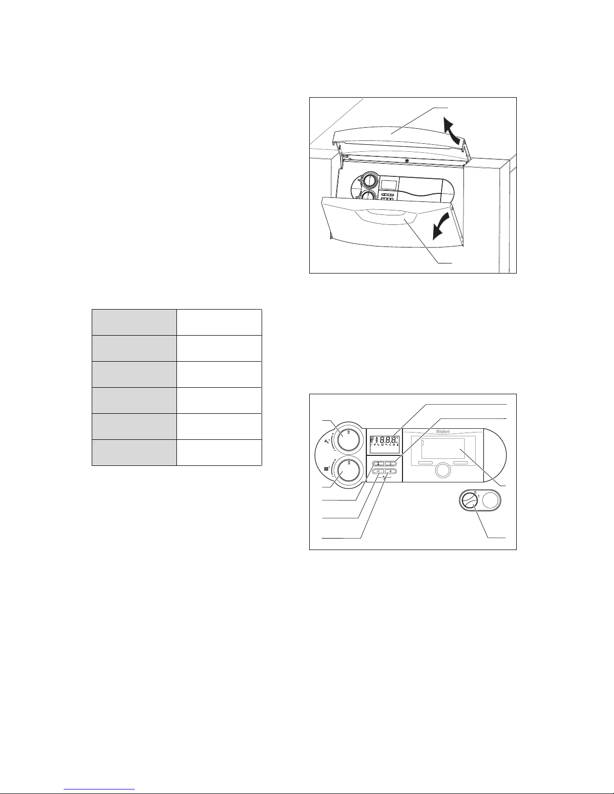
3.2 Opening the front flap
1
2
▶ Open the front flap by lifting the silver
handle bar (1).
◁ The front flap (2) automatically swiv-
els downwards and the control panel
becomes accessible.
3.3 Overview of the operator
control elements
1
9
8
7
6
5
2
3
4
1 Display
2 i button
3 Control (access-
ory)
4 Main switch
5 + button
6 − button
7 Fault clearance
key
8 Heating flow
temperature
rotary knob
9 Rotary knob for
the cylinder temperature in the
domestic hot water cylinder
The display shows the current heating flow
temperature, the system pressure of the
Page 8
3 Product description
8 Operating instructions ecoCRAFT exclusive 0020149575_01
heating installation, the operating mode or
certain additional information.
The i button is used to call up status information.
The controller, which is available as an
accessory, automatically controls the flow
temperature depending on the outside
temperature.
The main switch is used to switch the
product on and off.
The + button is used to display the cylinder
temperature (if the product is equipped
with a cylinder temperature sensor for the
domestic hot water cylinder).
The − button is used to display the filling
pressure of the heating installation.
The Reset button is used to reset the
product in the case of certain faults.
The heating flow temperature rotary knob
is used to set the heating flow temperature
if no controller is connected. If a controller
is connected, the heating flow temperature
rotary knob should be turned clockwise as
far as it will go.
The cylinder temperature rotary knob is
used to set the cylinder temperature if a
domestic hot water cylinder is connected.
If a control is connected, the rotary knob
should be turned clockwise as far as it
will go. The controller then determines the
cylinder temperature.
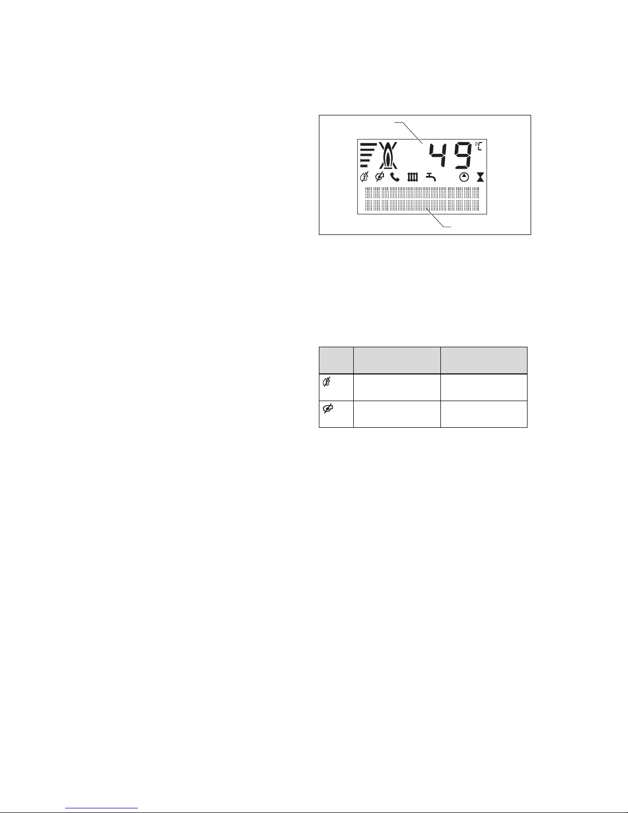
3.3.1 Digital Information and
Analysis System (DIA)
1
2
1 Display showing
the current heating flow temperature, the filling
pressure in the
heating installation, or a status
or fault code
2 Plain text display
Symbol
Meaning Explanation
Fault in the
air/flue gas route
Fault in the
air/flue gas route
Page 9

Product description 3
0020149575_01 ecoCRAFT exclusive Operating instructions 9
Symbol
Meaning Explanation
comDIALOG The heating flow
and domestic
hot water temperature are
specified via the
comDIALOG
communications
system. The
product works at
temperatures
other than those
set at the rotary
knob.
This operating
mode can only
be terminated by:
– comDIALOG
– Changing the
temperature
at the rotary
knobs by more
than ± 5 K
This operating
mode cannot be
terminated by:
– Pressing the
Reset button.
– Switching the
product off
and on again
Heating mode – Symbol per-
manently on:
Product is in
heating mode
operating
mode
– Symbol flash-
ing: Burner
anti-cycling
time is active
Symbol
Meaning Explanation
Hot water generation
– Symbol per-
manently visible: Charging
mode for the
domestic hot
water cylinder
is enabled by
the control and
floor-standing
boiler control
system
– Symbol
flashes: Domestic hot
water cylinder is being
heated
Heating pump
operating
Solenoid valve is
actuated
Gas supply to the
burner is open
Current energy
demand
Display of the
current burner
modulation
rate (bar graph
display)
Fault during
burner operation
Burner is
switched off
Burner operating
correctly
Burner is
switched on
3.4 Benchmark
Vaillant is a licensed member of the
Benchmark Scheme which aims to improve the standards of installation and
commissioning of domestic heating and
hot water systems in the UK and to encourage regular servicing to optimise
safety, efficiency and performance.
Page 10

4 Operation
10 Operating instructions ecoCRAFT exclusive 0020149575_01
Benchmark is managed and promoted
by the Heating and Hotwater Industry
Council. For more information visit
www.benchmark.org.uk.
▶ Please ensure that the installer has fully
completed the Benchmark Checklist on
the inside back pages of the installation
instructions supplied with the product
and that you have signed it to say that
you have received a full and clear explanation of its operation. The installer
is legally required to complete a commissioning checklist as a means of
complying with the appropriate Building Regulations (England and Wales).
All installations must be notified to Local
Area Building Control either directly or
through a Competent Persons Scheme.
A Building Regulations Compliance Certificate will then be issued to the customer
who should, on receipt, write the Notification Number on the Benchmark Checklist.
This product should be serviced regularly
to optimise its safety, efficiency and performance. The service engineer should
complete the relevant Service Record on
the Benchmark Checklist after each service.
The Benchmark Checklist will be required
in the event of any warranty.
3.5 CE label
The CE label shows that the products
comply with the basic requirements of the
applicable directives as stated on the identification plate.
The declaration of conformity can be
viewed at the manufacturer's site.
4 Operation
4.1 Starting up the product
4.1.1 Opening the isolator devices
1. Ask the competent person who in-
stalled the product to explain to you
where these isolator devices are located and how to handle them.
2. Open the gas isolator cock fully.
3. Check that the heating installation flow
and return service valves are open, if
such service valves are installed.
4. If a domestic hot water cylinder is con-
nected, open the cold-water isolation
valve. To check, you can turn on a hot
water valve and see whether water is
escaping there.
4.1.2 Switching on the product
1
2
1. Use the main switch (1) to switch on
the product.
◁ 1: "ON"
◁ When the main switch is in position
1, the product is switched on and
the standard display for the Digital
Information and Analysis System is
shown in the display (2). The function menu is immediately shown in
the display once the unit has been
switched on. The function menu enables competent persons to control
how the individual actuators work.
The product returns to normal operating mode after a waiting period of
Page 11

Operation 4
0020149575_01 ecoCRAFT exclusive Operating instructions 11
approximately five seconds or if the i
button is pressed.
2. Set up your product according to your
needs.
4.1.3 Switching off the product
1
▶ Use the main switch (1) to switch off the
product.
◁ 0: "OFF"
Note
In order for the protection functions, such as frost protection,
to remain activated, only activate and deactivate the product
using the control (you can find
information about this in the relevant operating instructions). If
no control is present, block the
heating and cylinder charging
mode by turning the dial to the
anti-clockwise end stop.
4.1.4 Checking the system pressure
1
▶ Check the heating installation's filling
pressure at regular intervals. Briefly
press the − (1) button.
◁ The display will show the filling pres-
sure for approximately 5 seconds.
◁ The filling pressure must lie between
1.0 and 2.0 bar when the heating installation is cold in order for the heating installation to operate properly. If
the pressure is lower, you must add
heating water before starting up.
Note
You can permanently switch
between the temperature or
pressure display in the display
by pressing and holding the –
button for approximately five
seconds.
Page 12

4 Operation
12 Operating instructions ecoCRAFT exclusive 0020149575_01
Note
To avoid operating the heating
installation with an insufficient
water volume and to prevent potential subsequent damage, the
product is fitted with a pressure
sensor. The pressure sensor
signals the low pressure level if
the level falls below 0.06 MPa
(0.6 bar). This is signalled by
the system pressure value in
the display flashing. If the level
falls below 0.03 MPa (0.3 bar),
the system displays the fault
message and F.22 alternately,
and the burner is blocked. If
the system pressure is lower
than 0.06 MPa (0.6 bar), fill the
heating installation up again as
quickly as possible. As soon as
the system pressure exceeds
0.06 MPa (0.6 bar), the product
starts up without any further
measures being required.
If the pressure sensor is defective, the product enters comfort safety mode. The maximum possible flow temperature and the power are limited.
The status S.40 and F.22 (water
deficiency) are displayed alternately.
Note
If the heating installation extends over several floors, a
higher system pressure for the
heating installation may be necessary. Ask your competent
person for details.
4.1.5 Filling the heating installation
Caution.
Risk of material damage due
to heating water that is extremely calciferous or corrosive or contaminated by chemicals.
Unsuitable tap water damages
the seals and diaphragms,
blocks components in the
product and heating installation
through which the water flows
and causes noise.
▶ Only fill the heating install-
ation with suitable heating
water.
▶ In case of doubt, ask a com-
petent person for details.
1. Ask a competent person where the
filling cock is located.
2. Connect the filling tap to a heating water supply in the way you were told by
the competent person.
3. Open all radiator valves (thermostatic
radiator valves) of the heating installation.
4. Open the heating water supply.
5. Slowly open the filling cock.
6. Fill it with water until the required filling
pressure is reached.
7. Close the filling cock.
8. Purge all radiators.
9. Then check the filling pressure on the
display.
10. Top up with more water if necessary.
11. Close the filling tap and the heating
water supply.
Page 13

Operation 4
0020149575_01 ecoCRAFT exclusive Operating instructions 13
4.1.6 Setting the heating flow
temperature (with control)
1
▶ Set the rotary knob for the heating flow
temperature (1) to the clockwise end
stop.
◁ The heating flow temperature is
automatically set by the control.
Note
To ensure that the control can
set temperatures up to the maximum heating flow temperature,
the rotary knob for the heating
flow temperature should always
be set to the clockwise end stop.
4.1.7 Setting the heating flow
temperature (without control)
2
1
▶ Set the target flow temperature on the
rotary knob for the heating flow temperature (1) in accordance with the outdoor
temperature.
Position Meaning
Outside temperature
Fully left Frost pro-
tection
Anti-clockwise (but not
at the end
stop)
Transition
Time
Approx.
10 … 20 ℃
Centre
Moderate
cold
Approx.
0 … 10 ℃
Clockwise
Extreme
cold
Below
0 ℃
◁ After turning the rotary knob for the
heating flow temperature, the display
shows the set target flow temperature (2). After three seconds, this
display goes out and the default
display reappears (current heating
flow temperature).
Note
The maximum heating flow temperature is set in the factory
at 75 °C. This can be defined
by the competent person to be
between 40 °C and 85 °C.
4.1.8 Setting the cylinder
temperature (with control)
1
1. Set the rotary knob for the cylinder
temperature (1) as far as it will go in
a clockwise direction so that the control
can work without any faults occurring.
2. Do not set the required cylinder tem-
perature at the rotary knob for the cylinder temperature; instead, set the
Page 14

4 Operation
14 Operating instructions ecoCRAFT exclusive 0020149575_01
temperature for the domestic hot water cylinder at the control.
Note
If you require a lower cylinder
temperature than 60 °C, we
recommend that you regularly
use the anti-legionella function
via the control.
4.1.9 Setting the cylinder
temperature (without control)
1
▶ Set the rotary knob for the cylinder tem-
perature (1) to the required cylinder
temperature.
Position Meaning Temperature
Fully left Minimum
cylinder
temperature = frost
protection
15 ℃
Centre Medium
cylinder
temperature
≈ 50 ℃
Fully right Maximum
cylinder
temperature
65 ℃
◁ The required temperature is shown
in the display. After three seconds,
this display goes out and the default
display reappears (current heating
flow temperature).
Note
The maximum cylinder temperature is set in the factory
at 65 °C. This can be defined
by the competent person to be
between 50 °C and 70 °C.
4.2 Switching off the product's
functions
4.2.1 Switching off cylinder
charging mode (using the VRC
630/VRS 620/VRC 700 control)
1. Leave the rotary knob for the cylinder
temperature at the clockwise end stop.
2. Switch the cylinder circuit to "OFF" on
the control.
Note
If the VRC 450 or 470 control is
available, switch cylinder charging mode off in accordance
with the section "Switching off
cylinder charging mode (without
a control) (→ Page 14)".
4.2.2 Switching off cylinder
charging mode (without
control)
▶ Turn the rotary knob for the cylinder
temperature to the anti-clockwise end
stop.
◁ Cylinder charging mode is switched
off.
◁ The frost protection function is activ-
ated for the domestic hot water cylinder.
◁ The display shows the target cylin-
der temperature of 15 °C for three
seconds.
Page 15

Troubleshooting 5
0020149575_01 ecoCRAFT exclusive Operating instructions 15
Note
The effect of the frost protection function is that, at cylinder
temperatures below 10 °C, the
domestic hot water generation
is switched on until the water in
the cylinder has reached 15 °C
again.
4.2.3 Switching off heating mode
(with control)
1. Leave the rotary knob for setting the
heating flow temperature at the clockwise end stop.
2. Switch heating mode to "OFF" on the
control.
4.2.4 Switching off heating mode
(without control)
▶ Turn the rotary knob for setting the
heating flow temperature to the anticlockwise end stop.
◁ Heating mode is switched off.
◁ The product's internal frost protection
function is activated.
4.3 Carrying out the flue gas
analysis
Note
Measurement and inspection work
must only be carried out by the
chimney sweep or competent person.
2
1
1. Switch on the chimney sweep function
by pressing the − (2) and + (1) buttons
for the DIA system at the same time.
◁ Shown in the display: S.Fh = Heat-
ing chimney sweep operation; S.Fb
= Domestic hot water chimney
sweep operation
◁ The product now works at maximum
load for 15 minutes. If you do not
press any buttons for 15 minutes
or if a flow temperature of 85 °C is
reached, the chimney sweep function is automatically switched off.
2. Take the measurements at the earliest
after three minutes of the product operating.
3. Unscrew the sealing caps from the
measuring stub pipe.
4. Take the measurement at the measuring stub pipe in the flue gas route.
5. Take the measurement at the measuring stub pipe in the air route.
6. Switch off the chimney sweep function
by pressing the − and + buttons for the
DIA system at the same time.
7. Screw the sealing caps onto the measuring stub pipe.
5 Troubleshooting
5.1 Detecting and rectifying faults
▶ If problems occur whilst operating your
product, you can carry out certain selfchecks with the aid of the table in the
appendix.
Troubleshooting (→ Page 20)
▶ If the product still does not function
without problems after the checks have
been carried out using the table, contact your competent person to rectify
the problem.
Page 16

5 Troubleshooting
16 Operating instructions ecoCRAFT exclusive 0020149575_01
5.2 Checking the product status
Heizbetrieb - Bren
1
2
1. Call up the product status by pressing
the i (2) button.
2. Switch the display (1) back to normal
operating mode by pressing the i button.
5.3 Status code meanings
The status codes that are shown in the
DIA system's display provide information about the product's current operating
status.
If several operating statuses occur at the
same time, the applicable status codes are
displayed alternately, one after the other.
The status code is explained a plain text
display in the display.
Status
code
Meaning
Heating mode
S.0 No heat demand
S.1 Fan start-up
S.2 Pump pre-run
S.3 Ignition
S.4 Burner on
S.6 Fan overrun
S.7 Pump overrun
S.8
Remaining anti-cycling time xx
min
S.31 No heat demand (summer mode)
S.34 Frost protection
Cylinder charging mode
S.20 DHW demand
S.22 Pump pre-run
S.24 Burner on
Status
code
Meaning
S.27 Pump overrun
5.4 F.22 Risk of dry fire
As soon as the system pressure falls
below 0.06 MPa (0.6 bar), the pressure
display flashes in the display along with
the current water pressure. As soon as
you have added sufficient water, the current flow temperature is displayed again.
If the pressure falls below 0.03 MPa
(0.3 bar), the product switches off. Fault
message F.22 appears in the display.
▶ Fill the heating installation with suitable
heating water and purge the heating
installation.
▶ If the pressure drops too frequently,
contact an approved heating specialist company. The cause of the loss in
heating water must be established and
eliminated.
5.5 F.28 No ignition on start-up
If the burner fails to ignite after three attempts, the product does not start up and it
switches to Fault.
The symbol is shown in the display.
▶ Check whether the gas isolator cock is
open.
▶ If the gas stopcock is closed, open the
gas stopcock with the agreement of an
installation company.
▶ Press and hold the reset button for
one second in order to cancel the ignition switch-off after three attempts.
▶ If the product does not start up after
three reset attempts, contact an approved heating specialist company.
Page 17

Care and maintenance 6
0020149575_01 ecoCRAFT exclusive Operating instructions 17
5.6 F.29 Flame goes out during
operation
The burner indicates flame loss during operation even though the flame has already
been detected for at least six seconds.
The product switches to Fault.
The symbol is shown in the display.
▶ Check whether the gas isolator cock is
open.
▶ If the gas stopcock is closed, open the
gas stopcock with the agreement of an
installation company.
▶ Press and hold the reset button for
one second in order to cancel the ignition switch-off after three attempts.
▶ If the product does not start up after
three reset attempts, contact an approved heating specialist company.
5.7 F.32 Risk of flue gas exit
If faults occur in the air/flue gas route
or condensate discharge, the product
switches off if three attempts at restarting
have been made (each with a waiting
period of 20 minutes) but failed.
The and symbols are shown in the
display.
▶ Contact an approved heating specialist
company.
6 Care and maintenance
6.1 Maintenance
An annual inspection of the product carried
out by a competent person is a prerequisite for ensuring that the product is permanently ready and safe for operation, reliable,
and has a long working life.
6.1.1 Checking the condensate
drain pipework and tundish
The condensate drain pipework and tundish must always be penetrable.
▶ Regularly check the condensate drain
pipework and tundish for faults and,
particularly, for blockages.
You must not be able to see or feel any
obstructions in the condensate drain pipework and tundish.
▶ If you notice a fault, have it rectified by
a competent person.
6.2 Caring for the product
Caution.
Risk of material damage
caused by unsuitable cleaning agents.
▶ Do not use sprays, scouring
agents, detergents, solvents
or cleaning agents that contain chlorine.
▶ Clean the casing with a damp cloth and
a little solvent-free soap.
7 Decommissioning
7.1 Temporarily decommissioning
the product
Caution.
Risk of material damage due
to frost
The frost protection and monitoring devices are only active
while the unit is connected to
the power mains, the product is
switched on via the main switch
and the gas stopcock is open.
▶ You must use the control
if you want to activate and
deactivate the product in
normal mode.
▶ If no control is present when
a main switch has been
switched on, set the rotary
Page 18

7 Decommissioning
18 Operating instructions ecoCRAFT exclusive 0020149575_01
knobs for the target heating
flow and cylinder values to
the anti-clockwise end stop.
▶ Do not disconnect the
product from the power
mains when it is in normal
mode.
▶ Leave the main switch in
position 1 in normal mode.
1
3
2
1. Turn the rotary knob for the cylinder
temperature (3) to the anti-clockwise
end stop.
2. Turn the rotary knob for the heating
flow temperature (2) to the anti-clockwise end stop.
3. If the fan continues to run, wait until it
stops.
◁ "Fan overrun" is shown in the
display.
4. Turn the main switch (1) to position 0.
5. Close the gas stopcock and the coldwater isolation valve.
Note
The isolators are not included
in the scope of delivery for your
product. They are installed onsite by the competent person.
Ask the competent person to
explain where the isolators are
located and how they are operated.
7.1.1 Preventing frost damage
The product is equipped with a frost protection function.
If the heating flow temperature falls below 5 °C when the main switch is switched
on, the product starts up and heats the circulating water on both the heating side
and the hot-water side (if available) to approx. 30 °C.
Caution.
Risk of material damage due
to frost.
The frost protection function
cannot guarantee flow through
the entire heating installation,
which means that parts of the
heating installation may freeze
and therefore become damaged.
▶ During a period of frost, en-
sure that the heating installation remains in operation and
that all rooms are sufficiently
heated, even when you are
away.
▶ Consult a competent person about this.
7.1.2 Draining the heating
installation
Another way to protect the heating installation and the product from frost for very
long switch-off times is to drain them completely.
▶ Consult a competent person about this.
Page 19

Recycling and disposal 8
0020149575_01 ecoCRAFT exclusive Operating instructions 19
7.2 Permanently
decommissioning the product
▶ Have a competent person permanently
decommission the product.
8 Recycling and disposal
▶ The competent person who installed
your product is responsible for the disposal of the packaging.
If the product is identified with this
symbol:
▶ In this case, do not dispose of the
product with the household waste.
▶ Instead, hand in the product to a collec-
tion centre for old electrical or electronic
appliances.
If the product contains batteries that
are marked with this symbol, these batteries may contain substances that are
hazardous to human health and the environment.
▶ In this case, dispose of the batteries at
a collection point for batteries.
9 Guarantee and customer
service
9.1 Guarantee
– Five year guarantee for ecoCRAFT
floor-standing appliances
Vaillant undertakes to rectify any manufacturing defect that occurs within
a five year period of the installation
date/manufacturing date (if the installation
date cannot be determined) provided that:
An annual service has been carried out by
a competent person approved at the time
by the Health and Safety Executive. The
cost of these services is not included in the
guarantee. The water flowing through the
boiler is maintained with adequate and
appropriate inhibitors. Any additional guarantee applies only if the boiler and system
has been maintained as above. If there is
no evidence that the boiler and system has
been maintained in an appropriate manner
the standard 1yr guarantee applies. Your
statutory rights are unaffected.
– Registering with us
Registration is simple and should be carried out by the installer and can be completed via any of the methods below. You
will need to have the full boiler serial number and installer Gas Safe registration
number to hand.
Visit our web site at:
www.vaillantcommercial.co.uk/guaranteeregistration
By telephone - Call 0345 693 3133
Alternatively - Just complete the Guarantee Registration Card and return to Vaillant
within 30 days of installation. Your details
will then be automatically registered within
the Vaillant scheme.
9.2 Customer service
To ensure efficient and reliable operation
of your boiler it is recommended that regular servicing is carried out by your service
provider.
Page 20

Appendix
20 Operating instructions ecoCRAFT exclusive 0020149575_01
Appendix
A Troubleshooting
Problem Possible cause Solution
No hot water,
heating stays cold;
product does not
start
Building gas isolator cock closed Open building gas isolator cock
Building power supply switched off Switch on building power supply
Main switch on the product is
switched off
Switch on the main switch on the
product
The heating flow temperature on the
control is set too low or in the "Heating off" position and/or the domestic
hot water temperature is set too low
Set the heating flow temperature
to the desired temperature and/or
set the hot water temperature to
the desired temperature
Filling pressure of the heating installation insufficient
Add more water to the heating
installation
Air in the heating installation Purging the radiators
If the problem occurs again: Inform the competent person
Ignition malfunction Press the reset button
If the problem occurs again: Inform the competent person
Hot water handling
mode without any
problems; heating
does not start
No heat requirement via the controller
Check the timer programme on
the controller and correct if necessary
Check the room temperature and,
if required, correct the target room
temperature ("Controller operating
instructions")
The heating flow temperature on
the control is set too low or is in the
"Heating off" position
Set the heating flow temperature
to the required temperature
Air in the heating installation Purging the radiators
If the problem occurs again: Inform the competent person
No hot water, heating mode functioning correctly
The hot water temperature on the
control is set too low or in the "Hot
water off" position
Set the hot water temperature to
the required temperature
Traces of water
under or next to the
product
Condensate drain pipework blocked Check and, if required, clean the
condensate drain pipework
Leak in the system or the product Close the cold water supply to
the product, inform a competent
person
Page 21

Appendix
0020149575_01 ecoCRAFT exclusive Operating instructions 21
B Gaskeur
Page 22

Page 23

Page 24

0020149575_01 17.11.2016
Supplier
Vaillant Ltd.
Nottingham Road Belper Derbyshire DE56 1JT
Telephone 0330 100 3461
info@vaillant.co.uk www.vaillant.co.uk
© These instructions, or parts thereof, are protected by copyright and may be
reproduced or distributed only with the manufacturer's written consent.
We reserve the right to make technical changes.
0020149575_01
 Loading...