

Vahle Apos KBH Series, Apos KBH 4/200 HS, Apos MKL Series, Apos KBH 5/200 HS Installation And Operation Instruction Manual

Montage und Bedienungsanleitung
APOS-Positioniersysteme
KBH und MKL
Installation and operation instructions
APOS positioning systems
KBH and MKL
Montage • Inbetriebnahme • Schnittstellen • Wartung
Installation • Commissioning • Interface • Maintenance

Montage und Bedienungsanleitung
Installation and operation instructions
APOS KBH - MKL
Inhaltsverzeichnis
1 Hinweise zur Dokumentation 3
1.1 Mitgeltende Unterlagen 3
1.2 Verwendete Symbole 3
2 Sicherheitshinweise 4
2.1 Qualifikation des Personals 4
2.2 Grundlegende
Sicherheitshinweise
3 Transport und Lagerung 5
4 Allgemeine technische Hinweise 5
4.1 Lieferumfang 6
4.2 Werkzeuge 6
4.3 Einziehrichtung des Codebandes
und Fixierprofils
4.3.1 Lage des Codebandews bei der
KBH und Verlegebeispiel
4.3.2 Lage des Codebandes bei der
MKL und Verlegebeispiel
4.4 Verlegungsplan 7
5 Montageablauf 8
5.1 Einziehen des Codebandes 8
5.2 Festpunkt 9
5.3 Lesekopfwagen 10
5.4 Anlagenenden 11
5.5 Montagecheck 11
5.6 Verbindung zum Fahrzeug 12
5.7 Elektrischer Anschluss 12
5.8 Betriebsstatusanzeige
(LED Meldungen)
5.9 Leseköpfe LB 15 13
5.9.1 Lesekopf LB 15
Ausgangsformat RS 485
5.9.2 Lesekopf LB 15
Ausgangsformat SSI Graycode
5.10 Probefahrt 15
6 Austausch der Einspeisungen
bei der KBH 15
6.1 Einspeisungen abklemmen 15
6.2 Einspeiseteilstück/
Einspeisung demontieren
6.3 Einspeiseteilstück/
Einspeisung wieder montieren
6.4 Einspeisung anschliessen 16
7 Wartung 16
8 Fehlerbehandlung 16
8.1 Allgemeines 16
8.2 Entstörmaßnahmen 17
13
13
14
15
15
Contents
1 Information on the Documentation 3
1.1 Additionally applicable documents 3
1.2 Symbols used 3
2 Safety instructions 4
2.1 Personnel qualifications 4
2.2 General safety instructions 4
4
3 Transport and Storage 5
4 General technical instructions 5
4.1 Scope of delivery 6
4.2 Tools 6
4.3 Threading in direction of the
6
7
7
code strip and the fixing profile
4.3.1 Position of the code strip
for the KBH and
arrangement example
4.3.2 Position of the code strip
for the MKL and
arrangement example
4.4 General installation drawing 7
5 Assembly procedure 8
5.1 Threading in the code strip 8
5.2 Fixed point 9
5.3 Reading head carrier 10
5.4 Ends of the system 11
5.5 Assembly check 11
5.6 Connection to the vehicle 12
5.7 Electrical connection 12
5.8 Operating status display
(LED messages)
5.9 Reading heads LB 15
5.9.1 Reading head LB 15
Source format RS 485
5.9.2 Reading head LB 15
Source format SSI Graycode
5.10 Trial run 15
6 Replacement of the power feeds
for the KBH 15
6.1 Disconnecting the power feeds 15
6.2 Dismantling the power feed
subsection/ power feed
6.3 Re-installing the power feed
subsection / power feed
6.4 Connecting the power feed 16
7 Maintenance 16
8 Handling faults 16
8.1 General information 16
8.2 Fault clearing measures 17
6
7
7
13
13
14
15
15
2

Montage und Bedienungsanleitung
Installation and operation instructions
APOS KBH - MKL
1 Hinweise zur Dokumentation
1.1 Mitgeltende Unterlagen
Diese Montageanleitung sowie alle mitgeltenden Unterlagen sind Teil des Produktes.
Sie müssen dem Anlagenbetreiber ausgehändigt werden. Dieser übernimmt die
Aufbewahrung, damit die Unterlagen bei
Bedarf zur Verfügung stehen.
1.2 Verwendete Symbole
Beachten Sie folgende Sicherheitshinweise
und sonstige Hinweise in der Anleitung.
Folgende Benennungen und Zeichen
werden in dieser Anleitung für besonders wichtige Angaben benutzt:
Symbol für eine Handlungsanwei-
sung:
Der Pfeil zeigt an, dass Sie eine Handlung durchführen sollen.
Lebensgefahr durch Strom-
B
schlag!
Hier finden Sie Hinweise auf
Situationen, bei denen die
Gefahr eines Stromschlags bestehen kann, und wie Sie diese
Gefährdung vermeiden können.
1 Information on the
Documentation
1.1 Additional documents
These mounting instructions and all additionally applicable documents are part of
the product. They must be handed over to
the plant operator. He is responsible for
keeping the documents so that they are
available for reference as required.
1.2 Symbols used
Please observe all safety instructions
and other information in this manual.
The following denominations and symbols are used in this manual for particularly important indications:
Symbol for instructions regarding
action:
This arrow indicates that you must take
action.
Danger to life by electric
B
shock!
Here, you will find information
on situations in which may
bring about the risk of electric
shock, and on how to avoid
this potential hazard.
a
S
H
Gefahr!
Unmittelbare Gefahr für Leib
und Leben! Hier finden Sie
Hinweise auf Situationen, bei
denen eine unmittelbare Personengefährdung besteht, und
wie Sie diese Gefährdung vermeiden können.
Achtung!
Mögliche Gefahr für Produkt
und Umwelt! Hier finden Sie
Hinweise auf Situationen, bei
denen Stromschienen oder
andere Anbauteile beschädigt
oder zerstört werden können,
und wie Sie diese Gefährdung
vermeiden können.
Hier erhalten Sie ergänzende
Hinweise.
a
S
H
Danger!
Immediate danger to life and
limbs! Here you will find information on situations in which the
immediate risk of danger to
persons may arise, and on how
to avoid this potential hazard.
Attention!
Potential danger to the product
and the environment! Here you
will find information about situations which may result in damage to the conductor rails or
other parts of the assembly,
and on how to avoid this
potential hazard.
Here you are provided with
additional information.
3

Montage und Bedienungsanleitung
Installation and operation instructions
APOS KBH - MKL
2 Sicherheitshinweise
2.1 Qualifikation des Personals
Montage, Installation und Wartung
dürfen nur durch ausgebildetes Fachpersonal erfolgen.
2.2 Grundlegende Sicherheitshinweise
Die Montageanleitung enthält Hinweise,
die Sie zu Ihrer persönlichen Sicherheit
sowie zur Vermeidung von Sachschäden
beachten müssen.
Montageanleitung lesen!
a
B
Sicherheitshinweise beachten!
Montageanleitung und Sicherheitshinweise vor der Montage
sorgfältig lesen und alle darin
enthaltenen Anweisungen genau befolgen.
Lebensgefahr durch Stromschlag!
Vor Beginn der Montagearbeiten
die Anlage unbedingt spannungsfrei schalten! Gefahr eines
Stromschlages bei fehlerhaftem
Anschluss des Geräts. Schalten
Sie vor der Installation von
Anschlüssen immer die Stromversorgung ab und sichern Sie
sie gegen Wiedereinschalten.
2 Safety instructions
2.1 Personnel qualifications
Assembly, installation and maintenance
work may only be carried out by trained
technical personnel.
2.2 General safety instructions
The mounting instructions contain information which must be observed for your
personal safety and for the avoidance of
damage to the equipment.
Read the assembly instructions!
a
B
Observe the safety instructions!
Carefully read the mounting
and safety instructions before
installation and exactly adhere
to the instructions contained
therein.
Danger of electric
shock!
Before starting the installation
work it is mandatory that you
disconnect the plant from the
mains! Danger of electric shock if
the equipment is incorrectly
connected. Always disconnect
the power supply before installing connections and secure
against being switched on again.
a
a
Gefahr durch unsachgemäße
Anwendung!
Nehmen Sie am Gerät keine
Veränderungen vor, die nicht in
dieser oder den mitgeltenden
Anleitungen beschrieben sind.
Gefahr durch Quetschen
zwischen bewegten und
festen Teilen!
Es muss sichergestellt werden,
dass durch die Anordnung von
Stromschienen und Schleifleitungen und Stromabnehmern
und Mitnehmerarmen die
Sicherheitsabstände von 0,5 m
zwischen
festen und beweglichen Anlageteilen zur Vermeidung von
Quetschgefahren nicht unterschritten werden!
a
a
Danger due to
improper use!
Do not make any changes to the
equipment, which are not described in these or in the
additionally applicable documents.
Risk of pinching between
mobile and fixed
components!
You must ensure that the
arrangement of the conductor
system provides minimum
distances (0.5 m) between
fixed and mobile plant parts
(i.e. between conductor rail,
collector trolleys and towing
arms) so as to avoid the risk of
pinching!
4
Montage und Bedienungsanleitung
Installation and operation instructions
APOS KBH - MKL
Beschädigungsgefahr!
a
Anlagenspezifische Dokumentation beachten!
Die folgenden Verlegungspläne
geben einen Überblick über die
prinzipielle Anordnung der Anlagenkomponenten.
Beachten Sie unbedingt die
anlagenspezifischen Unterlagen, in denen die auftragsbezogenen Verlegungspläne den
Anlagenaufbau abbilden.
3 Transport und Lagerung
Hinweise zu Transport und Lagerung
– Beachten Sie beim Transport die Ge-
wichtsangaben auf den Verpackungen.
– Lagern Sie die Bauteile immer auf einer
ebenen Unterlage.
– Die Umgebungstemperatur bei Trans-
port und Lagerung darf 60° C nicht
überschreiten.
– Vermeiden Sie insbesondere die Ver-
schmutzung des Codebandes durch
magnetisches Material.
4 Allgemeine technische
Hinweise
Danger of damage!
a
Observe the plant-specific
documentation!
The following installation
drawings provide an overview
of the basic layout of the plant
components.
Please make sure to observe
the plant-specific documents,
in which contain the order-related installation drawings illustrate the plant layout.
3 Transport and Storage
Information on transport and storage
– For transport, please observe the
weight stated on the packaging.
– Always store the components on an
even surface.
– The environmental temperature for
transport and storage must not exceed
60° C.
– Particularly avoid soiling of the code
strip by magnetic material.
4 General technical
instructions
Die Montage des Wegmessystems erfolgt nach der Schleif-
H
- Die Schleifleitungsenden sind nach der
APOS-Montage zu montieren.
- APOS kann nur bei geraden Anlagen
ohne Dichtlippen, Trichter, Dehnverbinder und Ausbaustellen eingesetzt
werden.
- Bei APOS- Nachrüstungen sind vorhandene Kopfeinspeisungen durch Streckeneinspeisungen zu ersetzen, vorhandene Strekkeneinspeisungen der KBH durch APOS
angepasste Einspeisungen ersetzen.
- Die Montage erfolgt mit zwei Personen.
Bei Einsatz von verfahrbaren Hubarbeitsbühnen ist zusätzliches Bedienpersonal erforderlich.
H
leitungsmontage. Die Schleifleitungsmontage und andere
Arbeiten sind entsprechend
der Montageanleitung KBH
bzw. MKL durchzuführen!
Montage von Anlagenlängen
> 150 m sind nur durch VAHLE
Monteure durchzuführen!
Eine gut ausgerichtete Anlage ist
Voraussetzung für eine einfache
Montage des APOS-Codebandes. Der Zustand bestehender
Anlagen ist zu überprüfen.
Gegebenenfalls ist die Anlage zu
Reinigen und Auszurichten, siehe
Montageanleitung.
The assembly of the positioning
system takes place after the
H
- The ends of the conductor line must be
mounted after the APOS assembly.
- APOS can only be used for straight
installations without sealing strips,
funnels, expansion joints and deinstallation points.
- For APOS retrofits, existing head power
feeds must be replaced by line feeds,
existing KBH line feeds must be
replaced by APOS adapted power
feeds.
- Installation is carried out by two people.
Additional staff is required for aplications with movable lifting platforms.
H
assembly of the conductor
line. The conductor line assembly
and other work must be carried
out in accordance with the KBH or
MKL mounting instructions!
Installations exceeding 150 m
have to be carried out by Vahle
mechanics.
A well aligned plant is the
prerequisite for easy assembly
of the APOS code strip. The
condition of existing plants
must be checked. If necessary,
the system must be cleaned
and aligned, see mounting
instructions.
5

Montage und Bedienungsanleitung
Installation and operation instructions
APOS KBH - MKL
An beiden Schleifleitungsenden sollte etwa
0,5 m Freiraum zum Einziehen des Codebandes vorhanden sein. Die Endkappen der
Schleifleitung müssen demontiert sein.
4.1 Lieferumfang
- Codeband
- Fixierprofil
- Lesekopfwagen mit montiertem Lesekopf (berührungslos)
- Zubehörset bestehend aus:
linkem Anlagenende
rechtem Anlagenende
Festpunkt
- Einziehrutscher
Optionaler Lieferumfang
- Schnittstellenbaustein
- Streckeneinspeisung, (nur bei
KBH-Nachrüstungen, falls erforderlich)
4.2 Werkzeug
- Schlitzschraubendreher
- Kreuzschlitzschraubendreher
- Maul- bzw. Ringschlüssel (7)
- Kombizange
- Seitenschneider
- Einziehrutscher
- 2 Paar Handschuhe
- Cuttermesser / Schere
- There should be about 0.5 m space
at the ends of the conductor line for threading in the code strip. The end caps of the
conductor line must be dismantled.
4.1 Scope of delivery
- Code strip
- Fixing profile
- Reading head carrier with mounted
reading head (contactless)
- Set of accessories consisting of:
left system end
right system end
fixed point
- Threading tool
Optional scope of delivery
- Interface module
- Line feed,
(only for KBH retrofits, if necessary)
4.2 Tools
- Slotted screwdriver
- Cross slot screwdriver
- Open-ended or box wrench (7)
- Combination pliers
- Side cutter
- Threading tool
- 2 pairs of gloves
- Cutter / scissors
Werkzeug optional:
- Handy, Funkgerät o.a. zur Verständigung
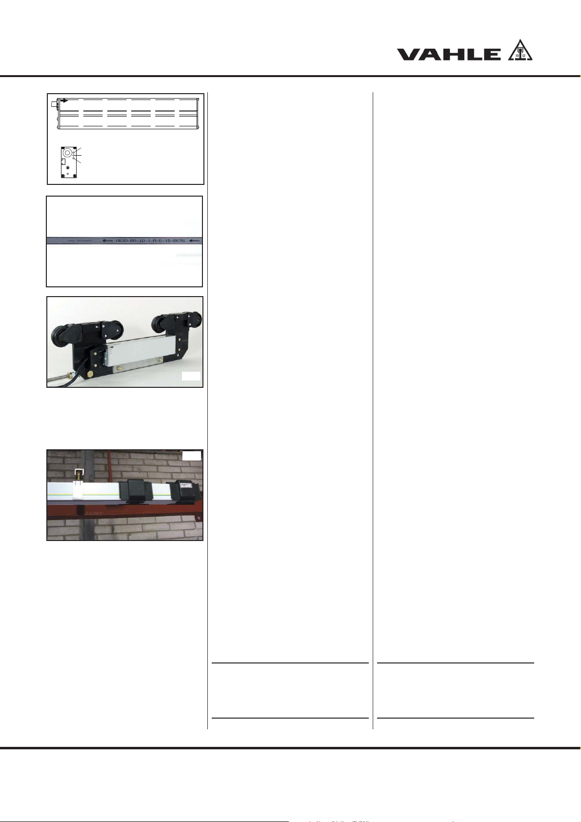
4.3 Einziehrichtung des Codebandes
und Fixierprofils
Achtung!
S
Die Pfeile auf dem Codeband (G17) und
dem Messwagen (G18) geben die
Zählrichtung des APOS-Systems an. Der
Pfeil auf dem Codeband zeigt entgegen
der Einziehrichtung der Bänder.
Bei der Montage bzw. Einführen
des Magnetbandes in die
Schleifleitung ist auf die Markierungen am Magnetband und am
Sensorkopf zu achten.
Eine falsche Richtung liefert
keine korrekten Werte!
Optional tools:
- Mobile phone, mobile radio set or
similar for communication
4.3 Threading in direction of the code
strip and the fixing profile
Attention!
S
The arrows on the code strip (G17) and
the measuring trolley (G18)indicate the
counting direction of the APOS system.
The arrow on the code strip points in the
opposite direction to the threading in
direction of the strips.
During assembly or threading
the magnetic strip into the conductor line, pay attention to the
markings on the magnetic strip
and the sensor head.
An incorrect direction does
not supply correct values!
6

Montage und Bedienungsanleitung
23
4
5
6
7
8
Installation and operation instructions
APOS KBH - MKL
4.3.1 Lage des Codebandes bei der
G1
KBH und Verlegebeispiel
Das Codeband (1) wird im Schacht
unterhalb der Schutzleiters (PE) von
1
rechts nach links eingezogen (auf PE gesehen). Siehe (G1) oder Verlegungsplan
4.3.1 Position of the code strip for the
KBH and arrangement example
The code strip (1) is threaded from right
to left in the shaft below the ground conductor (PE) (viewed on PE). See (G1) or
general installation drawing (G3).
(G3).
4.3.2 Lage des Codebandes bei der
MKL und Verlegebeispiel
Das Codeband (1) wird in den unteren
G2
Schacht gegenüber des Schutzleiters
(PE) von links nach rechts (auf PE gesehen) eingezogen. Siehe (G2) oder Verle-
gungsplan (G4).
1
Bei den Verlegeplanbeispielen zeigt der
Schutzleiter (PE) zur Kranbahn.
4.3.2 Position of the code strip for the
MKL and arrangement example
The code strip (1) is threaded from left
to right into the bottom shaft opposite
the ground conductor (PE) (viewed on
PE). See (G2) or general installation
drawing (G4).
In the installation drawing examples, the
ground conductor (PE) points towards
the runway.
4.4 Verlegungsplan
Die hier dargestellten beiden Verlegungspläne
sind typische Beispiele. Anlagenspezifische
Unterlagen bzw. auftragsgebundene Verlegungspläne sind primär zu berücksichtigen.
4.4 Installation drawing
Both installation drawings depicted here
are typical examples. Plant-specific
documents or order-related installation
drawings must be primarily considered.
1
"L"
Einzugsrichtung
APOS-Codeband
Pull-in direction
APOS-Code strip
23
1
"L"
Zählrichtung / Pfeilrichtung
APOS-Codeband und Sensor
Counting direction / direction of arrow
APOS-Code strip und sensor
6
7
Legende G3/G4
1 Kranbahn
2 Schleifleitung
3 Endkappe
4 Festpunkt Codeband
5 Streckeneinspeisung
6 Stoßabdeckkappen / Verbinder
7 Gleitaufhängung
8 Festaufhängung
{
Zählrichtung / Pfeilrichtung
APOS-Codeband und Sensor
Counting direction / direction of arrow
APOS-Code strip und sensor
5
8
4
{
Einzugsrichtung
APOS-Codeband
Pull-in direction
APOS-Code strip
Legend G3/G4
1 Runway
2 Powerail
3 Endcap
4 Fixpoint code-strip
5 Line feed
6 Joint cover /Joint
7 Sliding hanger
8 Fixpointhanger
G3
"R"
G4
"R"
7

Montage und Bedienungsanleitung
Installation and operation instructions
APOS KBH - MKL
5 Montageablauf
5.1 Einziehen des Codebandes
Die Montage des Codebandes und
G5
G6
G7
des Fixierprofils erfolgt mittels des
der Lieferung beiliegenden Einziehrutschers (G5).
Die Verpackungen von Code-
H
Die Codeband- und Fixierprofilver-
Das an der Oberseite der Verpackun-
Die Kunststoffbänder vom Codeband
band und Fixierprofil dienen
auch als Montagehilfe.
packungen an der Einzugsstelle so
aufstellen, dass der sich auf den Kartons befindliche Aufkleber „This side
up“ zur Schleifleitung hin und der
darauf abgebildete Pfeil nach oben
zeigt (G6).
gen fixierte Kunststoffband, an dem
Codeband bzw. Fixierprofil befestigt
sind, lösen und 0,5 m bis 1 m herausziehen (G7).
und Fixierprofil abschneiden.
5 Assembly procedure
5.1 Threading in the code strip
The assembly of the code strip and
the fixing profile takes place by
means of the threading tool, which is
included in the delivery (G5).
The packaging of the code
H
Position the code strip and fixing
Loosen the plastic strip fixed on the
Cut off the plastic strips from the
strip and the fixing profile also
serve as assembly aids.
profile packaging at the threading
point such that the sticker on the
boxes "This side up" points to the
conductor line and the arrow on it
points upwards (G6).
top side of the packaging, to which
the code strip and fixing profile are
attached, and pull out by 0.5 m to 1 m
(G7).
code strip and the fixing profile.
G8
H
Das Codeband und das Fixierprofil
G9
Beim Einziehen des Codebandes und des Fixierprofils ist
darauf zu achten, dass das
Magnetband nach unten zeigt
(G8).
parallel ausgerichtet an der Oberseite
des Einziehrutschers fest verschrauben (G9). Die Senkschraube muss
bündig mit der Oberkante des
Fixierprofils abschließen (G8).
When threading in the code
strip and the fixing profile,
H
Firmly screw down the code strip
please make sure that the
magnetic strip is pointing
downwards (G8).
and the fixing profile to the top of the
threading tool when aligned in parallel
position (G9). The countersunk-head
bolt must be flush with the top edge
of the fixing profile (G8).
8

Montage und Bedienungsanleitung
Installation and operation instructions
APOS KBH - MKL
Den Rutscher in den Montage-
G10
G11
G12
schacht der Schleifleitung einsetzen
(G10).
Achtung:
S
Komponenten durch langsames so-
Das Code- sowie Führungsband ist
Während des Einziehvorgangs Code-
Das Codeband muss beim
Einziehvorgang verschmutzungsfrei sein. Im Falle von
Verschmutzungen muss das
Band vor dem Einziehen gereinigt werden, z.B. durch eine
Reinigungstuch laufen lassen.
wie gleichmäßiges Ziehen einführen.
Der Winkel zwischen Schleifleitungslängsrichtung und Zugseil sollte unter
20 ° liegen (G11).
durch die zweite Montageperson zuführen. Dabei sind Handschuhe zu
tragen.
und Führungsband mit der einen
Hand gleichmäßig aus den Transportboxen herauszuziehen und mit
der anderen Hand in den Montageschacht einzuleiten (G12).
Insert the threading tool into the
mounting shaft of the conductor line
(G10).
Attention:
S
Insert the components by slow and
The code and guide strip must be
During the threading-in phase, evenly
The code strip must be free of
dirt. Clean the strip before inserting it if necessary, e.g. by
means of a cleaning cloth.
even pulling. The angle between the
longitudinal direction of the conductor line and the traction rope should
be below 20 ° (G11).
guided in by the second assembly
person. Gloves must be worn to do
so.
pull the code and guide strip out of
the transport box with one hand, and
thread them into the assembly shaft
with the other hand (G12).
G13
S
Beim Einzug auf einwandfreien Sitz
G14
Am Anlagenende das Codeband ca.
5.2 Festpunkt
Nach erfolgter Montage ist das
Achtung:
Codeband und Fixierprofil
langsam, etwas oberhalb des
Montageschachtes zuführen.
Die beiden einzelnen Profile
dürfen dabei nicht verdreht
sein (G13).
im Schacht achten. Falls erforderlich,
die Komponenten zurückziehen und
neu einbringen.
10 cm aus dem Gehäuse herauszuziehen und den Einziehrutscher
demontieren. Bei Bedarf das Band
auf der Gegenseite zurückziehen
(G14).
Codeband entsprechend Vorgaben
im Verlegungsplan zum Schleifleitungsgehäuse festzusetzen. Dies
erfolgt normalerweise am Festpunkt
der Schleifleitung.
Attention:
S
Check the correct position in the
At the end of the system, pull the
5.2 Fixed point
After completing the assembly, fix
Slowly guide the code strip
and the fixing profile slightly
above the assembly shaft. The
two individual sections must
not be twisted while doing so
(G13).
shaft when pulling in. If necessary,
pull the components back and thread
in again.
code strip out of the housing by
approx. 10 cm and dismantle the
threading tool. If necessary, pull the
strip back on the counterside (G14).
the code strip to the conductor line
housing in accordance with the
specifications in the installation
drawing. This normally takes place at
the fixed point of the conductor line.
9

Montage und Bedienungsanleitung
Installation and operation instructions
APOS KBH - MKL
Hierzu ist der Festpunktwinkel auf die
Schleifleitung aufzusetzen, so dass
sich der lange Schenkel auf der
Gehäuseseite mit dem APOS-Band
befindet.
Die beiden mitgelieferten Bohr-
G15
schrauben durch die beiden Bohrungen im Winkel in das Schleifleitungsgehäuse einschrauben (G15). Der
Festpunktwinkel muss dabei am
Gehäuse anliegen.
Durch die beiden Schrauben wird das
Codeband im Gehäuse verklemmt. Es ist
darauf zu achten, dass die Schrauben
nicht schräg eingeschraubt werden. Die
Schraube muss zwischen Codeband und
Lauffläche liegen. Das ist durch Tasten
von außen sowie beim Montagecheck
mit dem Lesekopfwagen von innen zu
überprüfen. Festgestellte Mängel beseitigen.
5.3 Lesekopfwagen
Achtung!
S
Bei Verwendung von APOS in
Verbindung mit der KBH 4/200 HS
und 5/200 HS müssen die sich
zwischen den Rädern befindlichen vier seitlichen Führungskufen vor dem Einsetzen in die
Schleifleitung vom Lesekopfwagen demontiert werden.
For this, the fixed point bracket must
be positioned on the conductor line
such that the long arm is on the
housing side with the APOS strip.
Screw the two enclosed drilling
screws into the conductor line
housing through the two holes in the
bracket (G15). The fixed point bracket
must contact the housing while doing
so.
The code strip is clamped into the housing
by the two screws. You must make sure
that the screws are not screwed in at an
angle. The screw must lie between the
code strip and the contact surface.
This must be checked by feeling from the
outside and from the inside during the
assembly check with the reading head
carrier. Remedy detected defects.
5.3 Reading head carrier
Attention!
S
In case of use of APOS with a
KBH 4/200 HS and 5/200 HS
the inbetween the wheels
existing lateral guiding skids
have to unassembeld from the
reading head before entering
the conductor!
Der Lesekopf muss auf dem
Lesekopfwagen montiert wer-
H
Der Lesekopf ist am Lesekopfwagen
Lesekopf von der Seite mit seiner Nut
S
Vor dem Einsetzen des Lesekopfwa-
den, bevor er in das Scheifleitungsgehäuse eingesetzt wird.
auf der gekennzeichneten Seite mit
den Anschlägen zu montieren.
auf die Schraubenköpfe schieben
und verschrauben.
Achtung!
Der Lesekopf muss beim Verschrauben gegen den oberen
Anschlag des Lesekopfwagens
gedrückt werden, damit der
Abstand zwischen Lesekopf
und Codeband minimal ist.
gens ist die Leserichtung des Wagens noch einmal zu kontrollieren.
Hierbei ist darauf zu achten, dass die
gekennzeichnete Sensorseite nach
oben zum Codeband zeigt!
Mount the reading head on the
H
Install the reading head at the carrier
Place the reading head from the side
S
The reading direction of the carrier
carrier before placing it into the
Powerail housing.
on the marked side with the stop.
with its groove onto the screw heads
and tight fit.
Attention!
Press the reading head against
the upper stop when screwing it
to keep the distance between
reading head and code strip as
small as possible.
must be checked once again before
inserting the reading head carrier. In
doing so, make sure that the marked
sensor side points upwards towards
the code strip!
10
Montage und Bedienungsanleitung
Installation and operation instructions
APOS KBH - MKL
+
Power
SCI
Error
grün / green
gelb / yellow
rot / red
Die Pfeile auf Lesekopf (G16) und Magnetband (G17) müssen in die gleiche
Richtung zeigen!
Der Lesekopfwagen ist an einem Anlagenende so einzuführen, dass der Lesekopf
unmittelbar unterhalb des Codebandes
liegt.
G16
G17
Führungswagen in die Sicherheits-
Schleifleitung einsetzen (G18).
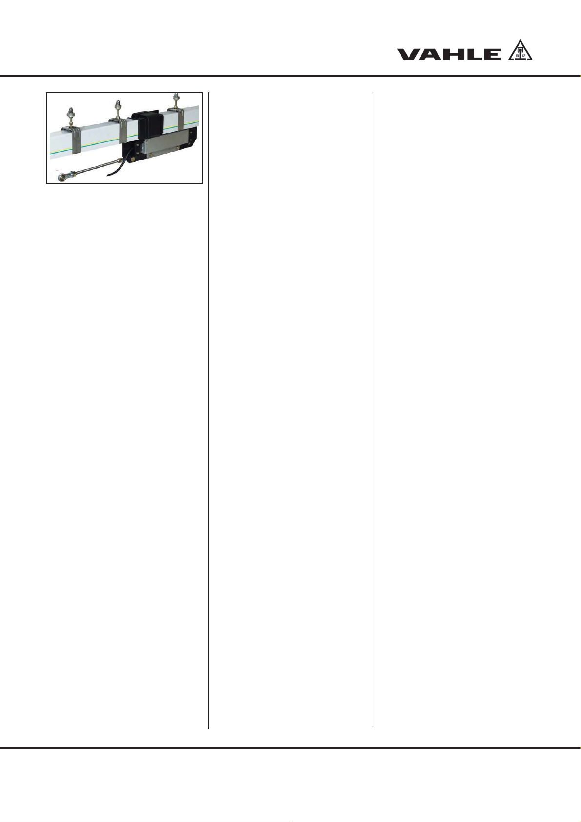
5.4 Anlagenenden
Das Codeband und das Fixierprofil
G18
G19
mit einer Kneifzange auf 100 mm
außerhalb des Gehäuses ablängen.
Danach die speziellen Endstücke an
beiden Schleifleitungsenden montieren. Das überstehende Codeband
und Fixierprofil in den entsprechenden Aufnahmeschacht der Endstücke
einführen.
Stoßabdeckkappen montieren (G19).
The arrows on the reading head (G16)
and magnetic strip (G17) must point in
the same direction!
The reading head carrier must be
inserted at one end of the system, such
that the reading head is situated directly
below the code strip.
Insert the guide carrier into the safety
conductor line (G18).
5.4 Ends of the system
Cut the code strip and the fixing
profile to a length of 100 mm outside
the housing using a pair of pliers.
After this, mount the special end
elements to both ends of the con ductor rail. Insert the protruding
code strip and fixing profile into the
corresponding mounting shaft of the
end elements.
Mount the joint cover caps (G19).
5.5 Montagecheck
Zur Überprüfung der korrekten Mon-
tage die gesamte Schleifleitung mit
dem Lesekopfwagen von Hand
durchfahren und auf Störstellen bzw.
Schwergängigkeit achten. Der Lesekopfwagen darf weder klemmen
noch springen oder kippen und muss
einen ausreichenden Abstand zu
möglichen Störkanten haben.
Festgestellte Mängel beseitigen.
Der korrekte Abstand zwischen Sensor und Magnet-
H
band beträgt bei der KBH etwa
3,5 mm und bei der MKL etwa
2,5 mm.
5.5 Assembly check
To check the correct assembly, travel
through the entire conductor line by
hand with the reading head carrier
and look for faults or stiffness.
The reading head carrier must neither
jam, nor jump, nor tilt, and must
have sufficient clearance from any
potentially disturbing edges.
Remedy detected defects.
The correct distance between
the sensor and the magnetic
H
strip is approx. 3,5 mm for the
KBH and approx. 2.5 mm for
the MKL.
11

4
1
3
2
1
2
3
4
8
5
6
7
Montage und Bedienungsanleitung
Installation and operation instructions
APOS KBH - MKL
RS 485
Legende /Legend G20
Belegung Stecker M 12
Plug arrangement M 12
1 braun /brown GND (0V)
2 weiß / white TX-
3 blau / blue TX+
4 schwarz / black 24 VDC
5.6 Verbindung zum Fahrzeug
Mechanische Verbindung vom Ge-
lenkkopf der Mitnehmerstange (M10)
zum Verbraucher herstellen.
Die gelenkige Mitnahmestange möglichst
parallel zur Schleifleitung ausgerichtet
anordnen.
Der horizontale Abweichung von der
Schleifleitung darf nicht größer als
5 °C sein, die vertikale Abweichung nicht
größer als 15 °C.
5.7 Elektrischer Anschluss
Der Lesekopf ist mit einer Schnittstelle
G20
RS 485 oder SSI ausgestattet.
Der Anschluss zur Steuerung wird über
einen 4-poligen-Steckerverbinder (G20)
oder 8-poligen Stecker (G21) mit M12x1
Schraubverschluss hergestellt. Die Daten
werden via interner Schnittstelle übertragen. Zusätzlich können externe Schnittstellenmodule (optional) mit Profibusoder Interbuskonvertierung angesteuert
werden.
5.6 Connection to the vehicle
Creating the mechanical connection
from the swivel head of the kelly
(M10) to the consumer.
Arrange the flexible kelly aligned as
parallel as possible to the conductor line.
The horizontal deviation from the
conductor line must not be larger than
5 °C, the vertical deviation not larger than
15 °C.
5.7 Electrical connection
The reading head is equipped with an
RS 485 or SSI interface.
The connection to the control system is
created via a 4-pole plug connector
(G20) or an 8-pole plug (G21) with M12x1
screw cap. The data is transferred via an
internal interface. In addition, external
interface modules (optional) with
Profibus or Interbus conversion can be
activated.
SSI Graycode
Legende /Legend G20
Belegung Stecker M 12
Plug arrangement M 12
1 weiß / white GND (0V)
2 braun / brown 24 VDC
3 grün / green Clock-
4 gelb / yellow Clock+
5 grau / grey Data-
6 rosa / pink Data+
G21
Achtung:
S
Der Biegeradius der Leitung muss mindestens 10x Leitungsdurchmesser betragen.
Der Schirm des Signalausgangskabels
sollte nur einseitig an die Nachfolgeelektronik angeschlossen und zentral mit
Schutzerde verbunden werden. Das
Signalausgangskabel ist grundsätzlich
getrennt von Laststromleitungen zu verlegen und ein Sicherheitsabstand von
mindestens 0,5 m zu induktiven und
kapazitiven Störquellen wie Schütze,
Relais, Motoren, Schaltnetzteile, getaktete Regler etc. ist einzuhalten.
Das Anschlusskabel ist so zu
verlegen und zu befestigen, dass
die Beweglichkeit des Lesekopfwagens nicht behindert wird und
dass sich die Leitung nicht an
festen Teilen der Gesamtanlage
verhaken kann.
Attention:
S
The bending radius of the cable must be at
least 10 times the cable diameter.
The screen of the signal output cable
should only be connected to the downstream electronics on one side and be
centrally connected to PE. The signal
output cable must generally be laid
separately from load current cables, and
a safety clearance of at least 0.5 m from
inductive and capacitive sources of
interference such as contactors, relays,
motors, switching power supplies, clocked
controllers etc. must be adhered to.
The connection cable must be
laid and fixed such that the movement of the reading head carrier is not impaired and the cable
cannot be caught in fixed parts
of the overall plant.
12
Montage und Bedienungsanleitung
Installation and operation instructions
APOS KBH - MKL
G22
5.8 Betriebsstatusanzeige
(LED Meldungen)
Die an der Stirnseite des Lesekopfes
angebrachten Leuchtdioden dienen zur
Anzeige bzw. der Überwachung der
Betriebszustände (G22).
GRÜN 씮 Versorgungsspannung
ON = System betriebsbereit
OFF = System ausgeschaltet
Gelb 씮 Interface
(Status der Schnittstelle)
Blinkt während der Übertragung
ROT 씮 ERROR
ON = Status Fehler, System
nicht betriebsbereit
OFF = Status OK, System
betriebsbereit
Bei der Inbetriebnahme und während des
Betriebs ist darauf zu achten, dass die
grüne LED leuchtet, da diese die internen
Versorgungsspannungen überwacht.
Das Blinken der gelben LED zeigt an,
dass die Datenübertragung korrekt erfolgt.
Das Leuchten der roten LED zeigt an,
dass beim Lesen ein Fehler vorliegt. Es
sind eine Fehlerbehandlung entsprechend Punkt 8.1 durchzuführen.
5.8 Operating status display
(LED messages)
The LEDs mounted on the face end of
the reading head serve to display or
monitor the operating statuses (G21).
GREEN 씮 Supply voltage
ON = System ready for operation
OFF = System deactivated
Yellow 씮 Interface
(Status of interface)
Flashes during transfer
RED 씮 ERROR
ON = Status error, system
not ready for operation
OFF = Status OK, system
ready for operation
During commissioning and operation,
you must make sure that the green LED
lights up, as it monitors the internal
supply voltage.
A flashing yellow LED indicates that data
transfer is taking place correctly.
When the red LED lights up, it shows that
a reading error is present. Fault treatment
must be carried out in accordance with
point 8.1.
5.9 Leseköpfe LB-15
5.9.1 Lesekopf LB-15
Ausgangsformat RS485
Schnittstelle = RS485
Datenübertragungsgeschwindigkeit = 19200 Baud
Datenform = 1 Startbit, 8 Daten
bits, 2 Stopbits,
keine Parität
Der Lesekopf sendet alle 10ms seine
Position auf RS485.
Eine Positionssendung besteht aus
3Byte, das höchstwertige Byte zuerst
das niederwertigste zuletzt. Das niederwertigste Bit des niederwertigsten Byte
hat die Wertigkeit 1mm.
5.9 Reading heads LB-15
5.9.1 Reading head LB-15
Source format at RS485
Interface = RS485
Data transfer
speed = 19200 Baud
Data form = 1 start bit, 8 data
bits, 2 stop bits,
no parity
The reading head sends its position to
RS485 every 10ms.
One position transmission consists of
3 bytes, the most significant byte first,
the least significant byte last. The LS bit
of the LS byte has a significance of 1mm.
13

Montage und Bedienungsanleitung
Installation and operation instructions
APOS KBH - MKL
(msb)
byte
position (n)
t
b2
byte 0
(lsb)
Legende G23
RS 485 Zeitdiagramm
tb2 (tbyte2) = 8,85 ms
tb1 (tbyte1) = 0,57 ms
tb0 (tbyte0) = 0,57 ms
tr (trate) = 10 ms
5.9.2 Lesekopf LB-15
Ausgangsformat SSI
Graycode / Binärcode
Im Sensor wird ein Schieberegister
permanent mit dem aktuellen Messwert
geladen. Wenn ein Datenwert gelesen
werden soll, gibt die Steuerung ein Taktpaket
(25 Bit) auf der Clockleitung aus. Die erste
fallende Flanke steuert ein Monoflop im
Sensor an, dass das Schieberegister vom
parallelen Laden in serielle Ausgabe
umschaltet. Bei jeder folgenden steigenden
Taktflanke wird jetzt ein Datenbit ausgegeben. Wenn das niederwertigste Bit empfangen wurde, wird der Takt gestoppt. Das
Monoflop, das von den Taktpulsen immer
nachgetriggert wurde, fällt nach Ablauf der
Schaltzeit wieder in den Grundzustand und
erlaubt wieder die Übernahme der Messwerte in das Schieberegister. Die Datenleitung
wird bis dahin auf Low-Pegel gehalten.
t
r
byte 2
(msb)
t
b1
bytebyte 2
position (n + 1)
t
b0
byte 0
(lsb)
Legend G23
RS 485 time diagram
tb2 (tbyte2) = 8.85 ms
tb1 (tbyte1) = 0.57 ms
tb0 (tbyte0) = 0.57 ms
tr (trate) = 10 ms
5.9.2 Reading head LB-15
Source format SSI
Graycode / Binärcode
A shift register with the current measured
value is permanently loaded in the
sensor. If a data value is to be read, the
control outputs a clock package (25 bit) on
the clock line. The first falling edge activates
a monoflop in the sensor, which switched
the shift register from parallel loading to
serial output. A data bit is now output for
each following rising clock edge. After the
least significant bit has been received, the
clock pulse is stopped. The monoflop,
which was always re-triggered by the clock
pulses, returns to its basic condition after
expiration of the switching time and again
enables the adoption of the measured
values into the shift register. Until then the
data line is kept at low level.
G23
14
Impulsdiagramm der Datenübertragung
Datanprotokoll: Auslesen der Daten (mit 25 Takten)
Data protocol: Data readout (with 25 clock pulses)
23 22 21 20 19 18 17 16 15 14 13 12 11 10 9 8 7 6 5 4 3 2 1 0
24 Datenbits/3Bytes
24 data bits/3 bytes
Wenn der Takt nicht für die Zeit Tm-T/2
unterbrochen wird (Ausgabe von weiteren
25 Perioden), taktet das Schieberegister
erneut den gleichen Datenwert heraus
(Fehlererkennung in der Auswertung). Einige Geberverfügen über ein Power Failure
Bit (PFB). Achtung: Beim APOS LB15 ist
das PFB immer „LOW“!
PFB = Power Failure Bit
T = Periodendauer des Taktsignals
Tm = Monoflopzeit > 10μs
max. Taktrate 울 150 kHz
T
PFB
G24
If the clock pulse is not interrupted for
the time Tm-T/2 (output of further 25 cycles),
the shift register again clocks out the
same data value (error recognition in the
evaluation). Some encoders have a
Power Failure Bit (PFB). Caution: The
PFB on the APOS LB15 is always
“LOW“!
PFB = Power Failure Bit
T = Cycle duration of the clock signal
Tm = Monoflop time > 10μs
max. clock rate 울 150 kHz

Montage und Bedienungsanleitung
Installation and operation instructions
APOS KBH - MKL
5.10 Probefahrt
Nach vollständige mechanischer und
elektrischer Inbetriebnahme ist mit
dem Fahrzeug eine Probefahrt mit
Schleichfahrt durchzuführen.
Abgelesene Positionen – Anfang und
Ende jeder Positionsstrecke – müssen nach der Installation in den Verlegungsplan eingetragen werden.
Es sind die Kontrollen entsprechend
5.5 und 8.1 durchzuführen.
Festgestellte Mängel beseitigen.
6 Austausch der Einspeisun-
gen bei einer KBH
Lebensgefahr durch Strom-
B
6.1 Einspeisung abklemmen
Öffnen der Abdeckung
Kabelschuhe von den Einspeiseklem-
Kabelverschraubungen von der Stirn-
Kabel mit Kabelverschraubung durch
schlag!
Anlage spannungsfrei schalten
- Spannungsfreiheit überprüfen
- gegen Wiedereinschalten
sichern.
men lösen
platte lösen
Stirnplatte herausziehen und zur
Wiedermontage in sicherer Anordnung/ Lage / aufbewahren / befestigen / ablegen / bereithalten.
5.10 Trial run
A trail run with the vehicle at crawl
speed must be carried out after
full mechanical and electrical commissioning.
Read-off positions "Start and
finish of each position line" must be
entered in the installation drawing
after installation.
Checks must be performed acc. to
5.5 and 8.1.
Remedy detected defects.
6 Replacement of power
supplies for a KBH
Danger to life by electric
B
6.1 Disconnecting the power feed
Opening the cover
Loosen the cable shoes from the
Loosen the cable gland from the face
Pull the cable with the cable gland
shock!
D
isconnect the plant from the mains
- check disconnected condition
- secure against switching on
again.
power supply terminals
plate
out through the face plate and
keep/fix/deposit/hold ready in safe
arrangement/position for re-assembly.
6.2 Einspeiseteilstück / Einspeisung
demontieren
Öffnen der Stoßkappen an beiden
Teilstückenden
Demontage der Federsteckverbinder
bzw. vollständiges Lösen der Schraubverbinder an beiden Kupferschienenenden
Schleifleitung wenn möglich von der
Einspeisung weg zur Seite schieben.
Teilstück entnehmen
Bei Schraubverbindern erleichtert
ein seitliches Verschieben des
H
6.3 Einspeiseteilstück / Einspeisung
Die Wiedermontage erfolgt in umgekehrter Reihenfolge zur Demontage
Neue Einspeisung von einer Seite her
Verbinder montieren
Die Schleifleitung ist ggfs. In die Aus-
Stoßkappen montieren
Teilstücks in Richtung eines
Stoßes die Demontage.
wieder montieren
einschieben
gangslage zurückzuschieben
6.2 Dismantling the power feed
subsection/ power feed
Open the joint caps at both ends of
the section
Disassemble the spring-loaded plug-
in connectors or full loosening of the
bolted joints at the copper conductor
rail ends.
If possible, push the conductor line to the
side, away from the power supply.
Remove the section
Disassembly of bolted joints is
facilitated by a lateral displa-
H
6.3 Re-installing the power feed
Re-assembly takes place in the reverse
order of the disassembly
Push in a new power feed from one
Mount the connectors
The conductor rail must be pushed
Mount the joint cap
cement of the section in the
direction of a joint.
subsection / power feed
side
back to its original position
15

Montage und Bedienungsanleitung
Installation and operation instructions
APOS KBH - MKL
6.4 Einspeisung anschließen
Das Anschließen der Einspeisung
erfolgt in umgekehrter Reihenfolge
zum Abklemmen der Einspeisung
Kabel mit Kabelverschraubungen
durch neue Stirnplatte ziehen und
daran befestigen
Kabelschuhe an den Einspeiseklem-
men befestigen
Abdeckung schließen
Überprüfung der elektrischen und
mechanischen Funktion.
7 Wartung
- Regelmäßig festen Sitz der Schrauben
überprüfen
- Lage des Sensors auf dem Lesekopfwagen kontrollieren und bei Bedarf korrigieren.
Die Oberkante des Sensors muss an der
Anschlagkante des Lesekopfwagens anliegen.
Kontrollen mind. alle 12 Monate oder in
Abhängigkeit von der Nutzung der Anlage
bzw. den örtlichen Betriebsbedingungen:
6.4 Connecting the power feed
Connecting the power feed takes
place in the reverse order of dis connecting the power feed
Pull the cable with the cable gland
through the new face plate and fix to
same
Fasten the cable shoes to the power
supply terminals
Close the cover
Check the electrical and mecha nical
function.
7 Maintenance
- Regularly check the firm seating of the
screws
- Check the position of the sensor on the
reading head carrier and correct if
necessary.
The top edge of the sensor must contact
the impact edge of the reading head
carrier.
Checks at least every 12 months or
depending on the use of the plant or the
local operating conditions:
- Verschmutzung
- Beschädigungen
- Ausrichtung der Anlage
- Ausdehnung des Magnetbandes
- Abstand Lesekopf zur Schleifleitung
(max. 4 mm) - die Lesekopfoberseite
muss spaltfrei am oberen Anschlag des
Lesekopfwagens anliegen.
- Neigung des Lesekopfs, ggfs. Anordnung
der Ausgleichsgewichte anpassen.
- Überprüfung des Laufradverschleiß
gem. Tabelle T1
Tabelle / Table T1
Laufräder Führungsräder Führungsräder
Runner wheels Guide wheels Guide wheels
LWK / LWM LWK LWM
Nennmaß Verschleißmaß in mm 44,5 15 29
Wear measure per mm 43,5 14 28
Wartungsarbeiten der Schleifleitung
entsprechend der jeweiligen Montageanleitung.
- Soiling
- Damage
- Alignment of the plant
- Expansion of the code strip.
- Distance reading head to Powerail
(max. 4 mm) – the upper side of the
reading head must lie against the upper
top of the carrier as close as possible.
- Adapt the inclination of the reading head
or compensation weights if necessary.
- Check wear of runner wheels as per
chart T1.
Maintenance work of the Powerail as per
respective installation procedure.
16

Montage und Bedienungsanleitung
Installation and operation instructions
APOS KBH - MKL
8 Fehlerbehandlung
8.1 Allgemeines
Bei einem Statusfehler am Lesekopf
(Aufleuchten der roten LED) sind folgende Punkte zu beachten:
Magnetband und Lesekopfwagen
sowie alle Kabelanschlüsse auf
Beschädigungen überprüfen.
Defekte Baugruppen sind zu ersetzen.
Der normale Abstand zwischen Sensor
und Magnetband beträgt bei der
KBH etwa 3,5 mm und bei der MKL etwa
2,5 mm.
- Die Lesekopfoberseite muss spaltfrei
am oberen Anschlag des Lesekopfwagens anliegen. Falls erforderlich den
Sensorabstand neu einstellen auf
Nennmaß.
- Gesamte Fahrstrecke in Schleichfahrt
oder von Hand mit dem Lesekopfwagen abfahren, um Störstelle zu lokalisieren.
- Falls erforderlich Entstörmaßnahmen
gemäß Punkt 8.2 durchführen.
8 Fault treatment
8.1 General information
The following points must be observed in
the event of a status fault on the reading
head (red LED lights up):
Check the magnetic strip and the
reading head carrier as well as all
cable connections for damage.
Defective assemblies must be replaced.
The normal distance between the sensor
and the magnetic strip is approx. 3,5 mm
for the KBH and approx. 2.5 mm for
the MKL.
- The upper side of the reading head
must lie against the upper top of the
carrier as close as possible. If necessary, re-adjust the sensor distance to nominal value.
- Travel along the entire track by hand
with the reading head carrier at crawl
speed to localise the fault.
- If necessary, carry out fault clearing
measures acc. to point 8.2.
8.2 Entstörmaßnahmen
Der Schirm des Signalausgangskabels
sollte nur einseitig an die Nachfolgeelektronik angeschlossen und zentral mit
Schutzerde verbunden werden. Das Signalausgangskabel ist grundsätzlich
getrennt von Laststromleitungen zu verlegen und ein Sicherheitsabstand von
mindestens 0,5 m zu induktiven und kapazitiven Störquellen wie Schütze,
Relais, Motoren, Schaltnetzteile, getaktete Regler etc. ist einzuhalten.
Sollten trotz Einhaltung aller oben
beschriebenen Punkte Störungen auftreten, muss wie folgt vorgegangen werden:
- Anbringen von RC-Gliedern über
Schützspulen von AC-Schützen
(z.B. 0,1μF / 100 Ω)
- Anbringen von Freilaufdioden über DCInduktivitäten.
- Anbringen von RC-Gliedern über den
einzelnen Motorphasen und über der
Motorbremse (im Klemmenkasten des
Motors).
- Schutzerde und Bezugspotential nicht
verbinden!
- Vorschalten eines Netzfilters am externen Netzteil.
8.2 Fault clearing measures
The screen of the signal output cable
should only be connected to the downstream electronics on one side and be
centrally connected to PE. The signal
output cable must generally be laid separately from load current cables, and a
safety clearance of at least 0.5 m from
inductive and capacitive sources of interference such as contactors, relays,
motors, switching power supply, clocked
controllers etc. must be adhered to.
If faults should still occur despite
ad herence to all points described above,
please proceed as follows:
- Attachment of RC-elements via contactor coils of AC contactors (e.g. 0.1μF /
100 Ω)
- Mounting of free wheeling diodes via
DC inductance.
- Attachment of RC-elements via the
individual motor phases and via the
motor brake (in the terminal box of the
motor).
- Do not connect PE and reference
potential!
- Prefix a mains filter on the external
PSU.
17

Montage und Bedienungsanleitung
Installation and operation instructions
APOS KBH - MKL
18

Montage und Bedienungsanleitung
Installation and operation instructions
APOS KBH - MKL
19

Montageanleitung zu Katalog Nr. 7a/D 2009
Mounting instructions for catalog No. 7a/E 2009
MANAGEMENTSYSTEM
DQS - zertifiziert nach DIN EN ISO 9001:2008
OHSAS 18001:2007
(Reg.-Nr. 003140 QM 08/BSOH)
certified by DQS according to Din EN
ISO 9001:2008 OHSAS 18001:2007
(Reg. Nr. 003140 QM 08/BSOH)
09 • Printed in Germany • 2517671 • 09
PAUL VAHLE GMBH & CO. KG • D 59172 KAMEN/GERMANY • TEL. (+49) 23 07/70 40
Internet: www.vahle.de • E-Mail: info@vahle.de • FAX (+49) 23 07/70 44 44
 Loading...