


Technical Manual
Instructions for installation,
operation and maintenance
662B
PEM2 TOUCH SCREEN
For T-Sense® optical torque and
TT-Sense® optical thrust and torque measuring systems
Publication nr
TIB-662B-GB-0616
Supersedes
TIB-662B-GB-0114

TABLE OF CONTENTS
1.
PREFACE ....................................................................................... 3
1.1 General ........................................................................................................ 3
1.2 Symbols ....................................................................................................... 3
1.3 Copyright ..................................................................................................... 3
2. SYSTEM DESCRIPTION ................................................................ 4
2.1 PEM2 TOUCH SCREEN ............................................................................. 4
2.2 System security............................................................................................ 4
3. TECHNICAL SPECIFICATIONS ..................................................... 5
3.1 PEM2 TOUCH SCREEN ............................................................................. 5
4. SAFETY INSTRUCTIONS .............................................................. 5
5. UNPACKING .................................................................................. 5
6. INSTALLATION AND FIRST USE .................................................. 7
6.1 To record nameplate data ............................................................................ 7
6.2 Installation diagram ...................................................................................... 8
6.3 Installation of the PEM2 touch screen .......................................................... 9
6.4 Cable specifications ................................................................................... 13
7. OPERATING PRINCIPLES .......................................................... 14
7.1 General ...................................................................................................... 14
7.2 Displayed parameter and engineering units ............................................... 14
7.3 Explanation of the parameters ................................................................... 14
7.3.1 Torque .............................................................................................. 14
7.3.2 Shaft speed ....................................................................................... 14
7.3.3 Power ................................................................................................ 14
7.3.4 Thrust (option) ................................................................................... 14
7.4 Operating instructions PEM2 touchscreen ................................................. 15
7.4.1 Operating menus .............................................................................. 15
7.5 How to operate the touch screen ............................................................... 15
7.5.1 Main menu ........................................................................................ 16
7.5.2 T-Sense® monitoring ......................................................................... 16
7.5.3 Propulsion data ................................................................................. 17
7.5.4 Info Screen ........................................................................................ 17
7.5.5 Settings menu ................................................................................... 18
7.5.6 Alarm Settings ................................................................................... 19
7.6 Method of calculations ............................................................................... 20
8. MAINTENANCE ............................................................................ 21
9. REPAIR ........................................................................................ 21
10. TAKE OUT OF SERVICE ......................................................... 21
11. REMOVAL AND STORAGE OF EQUIPMENT ......................... 21
12. MALFUNCTION AND SEND FOR REPAIR ............................. 21
13. ENVIRONMENT ....................................................................... 21
14. DISPOSAL ................................................................................ 21

2
15. TROUBLE SHOOTING ............................................................. 22
15.1 PEM2 malfunction ................................................................................... 22
15.2 No torque signal ...................................................................................... 22
16. CERTIFICATES ........................................................................ 22
16.1 EMC classifications of the PEM2 ............................................................ 22
17. DRAWINGS .............................................................................. 23
18. ABBREVIATIONS ..................................................................... 29
19. SPARE PARTS ......................................................................... 29
20. WARRANTY CONDITIONS ...................................................... 30

3
1. PREFACE
1.1 GENERAL
The PEM2 touch screen is a microprocessor based instrument, which is able to fulfil standard torque,
shaft speed and power calculations within narrow limits. Thrust and thrust/power calculations can be
performed when thrust measurements are available.
The T-Sense
®
torque sensor is the measuring instrument providing torque, speed and power as input
for the PEM2 touch screen. The TT-Sense
®
additionally provides thrust measurements as input. This
completely unique and compact total solution can be used for simple to complicated configurations.
Never use the equipment outside its specifications or beyond common engineering
practice nor use the equipment for other applications or make connections to other
equipment than explicitly described in the order acknowledgement and/or technical
manuals of VAF Instruments.
To ensure safe and correct installation and operation, read this manual completely before
installing the equipment and starting operations.
For any additional information contact:
VAF Instruments B.V.
Tel. +31 78 618 3100
Vierlinghstraat 24, 3316 EL Dordrecht Fax +31 78 617 7068
P.O. Box 40, NL-3300 AA Dordrecht E-mail: sales@vaf.nl
The Netherlands Internet: www.vaf.nl
Or your local authorized VAF dealer.
Their addresses can be found on www.vaf.nl
1.2 SYMBOLS
The following symbols are used to call attention to specific types of information.
A warning to use caution! In some instances, personal injury or damage to the torque
sensor or control system may result if these instructions are not followed properly.
An explanation or information of interest.
1.3 COPYRIGHT
This Technical Manual is copyrighted with all rights reserved.
While every precaution has been taken in the preparation of this manual, no responsibility for errors or
omissions is assumed. Neither is any liability assumed for damages resulting from the use of the
information contained herein. Specifications can be changed without notice.

4
2. SYSTEM DESCRIPTION
2.1 PEM2 TOUCH SCREEN
The PEM2 touch screen is able to calculate several output data.
Functions, which can be performed with this PEM2 touch screen are:
Measurement and display of torque, shaft speed, power and thrust (optional).
Calculation of average shaft power, shaft speed and torque during the last 1, 4 and 24 hours.
Calculation of total energy and total revolutions including reset.
Calculation of average thrust/quotient when thrust measurement (optional) is provided.
Displaying of parameters.
The PEM2 touch screen can be installed in a control cabinet or control panel.
Remark:
Optional 4-20 mA analogue output can be integrated in the stator control box near the TSense
®
torque sensor. Please read section 6.5 in TIB-661 for detailed information or read
TIB-664 section 6.5 in case of TT-Sense
®
torque/thrust sensor.
2.2 SYSTEM SECURITY
Besides checking the status of the torque measurement system the PEM2 system also checks itself
continuously for program and configuration data integrity, normal program flow and power supply
conditions. Alarm messages will be logged in a dedicated alarm screen.

5
3. TECHNICAL SPECIFICATIONS
3.1 PEM2 TOUCH SCREEN
Supply voltage 24VDC ±10%
Dimensions
188 x 143 x 46 mm (w x h x d)
Cut out
174.5 x 132.5 mm (w x h)
Cut out depth
40 mm
Front panel thickness
6 mm
Connections
screw terminals and RS485 connection on back panel
Temperature range
0 - 55 deg. C
Display
Color TFT-Touch screen 5.6” (320x234 dots) with (optional)
adjustable LED backlight
Protection class
IP 65 at front facia
Power consumption
10 W
Processor (CPU)
ARM926EJ-S 32bits, 200 MHz, 32 MB SDRAM
Net weight
0.8 kg
Figure 1 – PEM2 touch screen
4. SAFETY INSTRUCTIONS
There are no special safety instructions for the equipment.
5. UNPACKING
Let the equipment acclimatize inside the closed box for at least one hour at the location where the
system will be installed.
When the equipment is taken out of the box, please leave the special protection supplied with the
equipment as long as possible in place to avoid any damage.
The special protection should be stored for the unlikely event the equipment has to be sent for repair.
Dispose of the packing material should be done according to the laws of the country where the
equipment is installed, or according to the rules that are applicable on the vessel.
Be careful when unpacking the electronic equipment. The content is fragile.
Do not press on the PEM2 touch screen.

7
6. INSTALLATION AND FIRST USE
The PEM2 touch screen will be delivered with the software and correct data settings installed. First
connect the Modbus input and optional Modbus output cables to the touch screen.
The 24 VDC wires for power supply should be connected at last.
Note: There is no ON/OFF switch on the PEM2 touch screen. When the power supply is switched on
these screens will turn on.
Check if the inputs show any errors. If that is the case the connection(s) or connected equipment
should be checked and corrected.
6.1 TO RECORD NAMEPLATE DATA
This information is required when contacting the supplier for any reason.
Date of delivery: Xx xxxxxxx xxxx
Serial number: xxxxxxxxx
Hull number: xxx
Type: PEM2 touch screen
Above information can be found at the PEM2 info screen.

8
6.2 INSTALLATION DIAGRAM
The PEM2 touch screen can be connected to the stator control box as shown in Figure 2 and Figure 3.
The maximum number of touch screens, which can be connected by RS485 Modbus serial connection
is two.
Figure 2 – T-Sense® torque sensor connected to one PEM2 touch screen
Figure 3 – Example of T-Sense® torque sensor connected to two PEM2 touch screens
Remark:
When a TT-Sense
®
Thrust & Torque sensor is installed it can be connected in the same
way as above mentioned T-Sense
®
equipment.
9
6.3 INSTALLATION OF THE PEM2 TOUCH SCREEN
1. Install the PEM2 touch screen in a control cabinet or control panel in the ECR or on the bridge,
where it will be free as possible from moisture, large fluctuations of temperature and particularly of
vibration shock. Also influences such as large magnetic fields caused by transformers, relays or
electromagnets must be avoided.
2. All cable connections should be made using cables as specified in section 6.4.
3. Connect the RS485 Modbus cable from the stator control box and 24VDC power supply to the
backside of the PEM2 touch screen in accordance with Figure 4 and Figure 5.
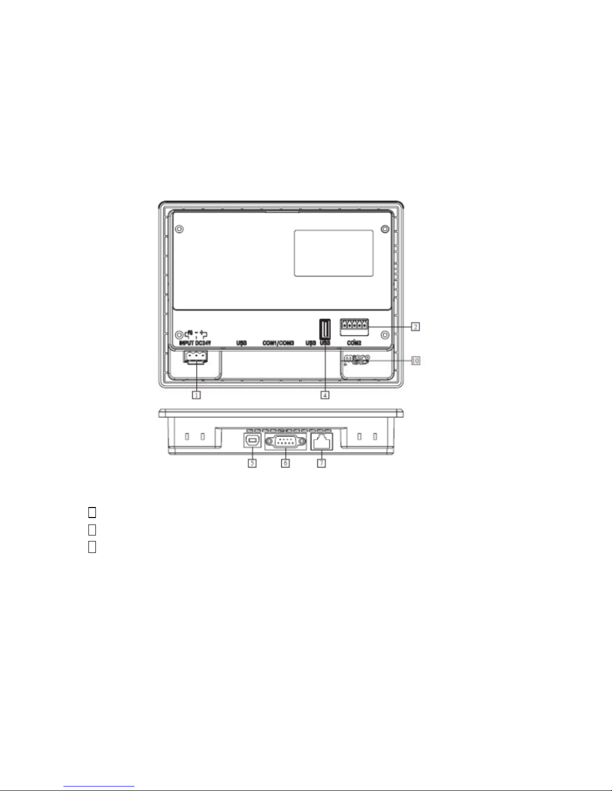
1 24VDC power supply connector
2 COM2, 5-Pin terminal for data input via RS485 Modbus cable
6 COM1, 9-Pin female for data output/transfer to additional PEM2 touch screen
Figure 4 – Power supply and communication ports at backside of PEM2 touch screen

10
Figure 5 – Power supply and RS485 Modbus cable connection to PEM2 touch screen
4. Ensure that the Modbus cable is properly shielded and grounded as close as possible to the stator
control box. The Modbus cable shield cannot be connected to the touch screen.
5. Check for correct DC supply power and integrity of external wiring connections. Turn on power and
observe several readings, like torque, shaft speed, power etc. If not, check wiring and verify whether
the inputs are in agreement with actual value.
Important notes
Never connect cable shields at both ends to ground, but at one end only,
to avoid
earth loops.
To avoid interference on the signal cables, such cables must be installed as far as
possible from electric power cables used for power supply and stator.
Ensure that the ambient temperature at the PEM2 never exceeds 55°C (131°F).
 Loading...